Department of Biotechnology and Chemical Technology
Master’s Programme in Process Systems Engineering
Sanjay Shah
HYDROGEN PRODUCTION PROCESSES FROM
BIOMASS
Master’s thesis submitted for inspection,
Espoo, 18 December 2014
Supervisor: Professor Jukka Koskinen
Aalto University, P.O. BOX 11000, 00076 AALTO www.aalto.fi
Abstract of Final Project Author Sanjay Shah
Title of final project Hydrogen production processes from biomass Department Biotechnology and Chemical Technology
Professorship Plant Design Code of professorship KE-107
Thesis supervisor Professor Jukka Koskinen
Thesis advisor(s) / Thesis examiner(s) Matti Sonck (M.Sc.) & Sara Kärki (M.Sc.)
Date 18.12.2014 Number of pages
98+7
Language English
Abstract
Global warming, climate change and energy security have been gaining more attention worldwide. Hydrogen production from biomass offers an effective solution leaving minimal environmental footprint. This thesis identifies and reviews the most potential bio-hydrogen production pathways, identifies and designs the most promising process, and then conducts a rough feasibility study to check its economic potential for commercial production after simulation (experimental part). Finally, it also tests the viability of the developed process against non-bio-hydrogen process.
Based on literature review, it is concluded that biomass gasification technology is the most promising process for bio-hydrogen production. Simulation results show that 67.5% product efficiency with 99.99% purity and >82% overall efficiency are achieved using forest residues as the biomass feedstock in a plant capacity of 100 MW. The product efficiency of this process might be lower than the product efficiency achieved by hydrogen production from natural gas, which is >80%, but the designed process has low carbon footprint and has higher efficiency compared to other biological and thermochemical processes.
The results from cost analysis show that the production cost of hydrogen based only on its hydrogen production efficiency for the base case accounts to 93 €/MWh. For the same base case, the calculated internal rate of return (IRR) is 7.46%. Sensitivity analysis shows that in order for IRR to increase from ~7.5% to 15%, either the hydrogen selling price should increase from 90 €/MWh to 125 €/MWh while keeping the rest of variables constant. Alternatively, the fixed capital investment (FCI) should decrease from 200M€ to 150M€ and the hydrogen selling price should increase from 90 €/MWh to 99 €/MWh. To conclude, this study shows that biomass gasification technology is the most promising bio-hydrogen production process and hence should be considered for commercial production.
Keywords hydrogen, production, processes, design, bio-hydrogen, literature review, thermochemical, biological, efficiency, sensitivity analysis
ACKNOWLEDGEMENTS
This thesis is written within the Plant Design Group and Fortum Corporate R&D Team during summer and spring 2014. Summer 2014, I was offered an opportunity to do my thesis about hydrogen production processes from biomass in Fortum, Keilaniemi. The hospitality of every member of the group/team is sincerely appreciated; the comments and suggestions during the writing process, the smiling faces at the workplace, the expertise advices and also the friendly administrative services.
I am thankful to my supervisor Professor Jukka Koskinen, and instructors D.Sc. Golam Sarwar, M. Sc. Matti Sonck and M.Sc. Sara Kärki, for thesis related help, instructions and their contribution. Their comments during the project and meetings are all appreciated. Furthermore, I am grateful to B. Sc. Sebastian Johansson, D. Sc. Esa Kurkela and M. Sc. Kristian Melin for overseeing the work as well as giving valuable and motivating advices.
Finally, I would like to express my thanks to all my dear friends and family members. My elders have always supported me during my studies, special thanks to my mom. Thank you for your trust and love.
LIST OF NOMENCLATURE
Symbols∆G0 Standard state Gibbs free energy change (joule) gdwt Gram dry weight (kg)
m Mass (kg) p Pressure (bar) T Temperature (°C) x Moisture content (%) @ At the rate % Percent < Less than > Greater than ≈ Approximately equal $ American dollar € Euro Greek letters ρm Gravimetric density ρv Volumetric density γ Relative humidity Abbreviations
ADP Adenosine diphosphate
AnSBR Anaerobic sequencing batch reactor
ATP Adenosine triphosphate
AR Air ratio
ATR Auto-thermal reforming
C Carbon
CHP Combined heat and power
COD Chemical oxygen demand
CSTR Continuously stirred tank reactor
Da Dalton
EDTA Ethylenediaminetetraacetic acid
ER Equivalence ratio
FBR Fluidized bed bioreactor FCI Fixed capital investment cost
GHG Greenhouse gas
H Hydrogen
HHV Higher heating value
HRT Hydraulic retention time
HT High temperature
IRR Internal rate of return
LHV Lower heating value
LNG Liquefied natural gas
LPG Liquefied petroleum gas
LT Low temperature
MOF Metal-organic framework
MSW Municipal solid waste
MW Megawatt
N Nitrogen
NRTL Non-random-two-liquid model
O Oxygen
O&V Other fixed and variable costs
pH Percentage of hydrogen
PFOR Pyruvate ferredoxin oxido-reductase
POME Palm oil mill effluent
POX Partial oxidation
PS Photosystem
PSA Pressure swing adsorption
RT Room temperature
R&D Research and development
S Sulphur
SCW Supercritical water gasification
SMR Steam methane reforming
SRK Soave-Redlich-Kwon
S/B Steam-to-biomass ratio
TVS Total volatile solid
U.R. Under research
vol. Volume
V Voltage
wt. Weight
Table of Contents
Chapter 1 ... 1
1.1 Introduction ... 1
1.2 Goal, Objectives and Scope ... 2
1.3 Structure ... 3
I Theoretical Part ... 4
Chapter 2 ... 4
2.1 Bio-Hydrogen Properties... 4
2.2 Hydrogen Applications ... 6
2.3 Hydrogen Storage and Distribution ... 7
2.4 Raw Materials and Their Characteristics ... 10
Chapter 3 ... 12 3.1 Production Processes ... 12 3.2 Thermochemical Processes ... 18 3.2.1 Pyrolysis ... 18 3.2.2 Liquefaction ... 19 3.2.3 Gasification ... 21
3.3 Thermochemical Technologies for Hydrogen Production from Biomass ... 23
3.3.1 Hydrogen from Biomass Gasification ... 23
3.3.2 Hydrogen Production from Gasification in Supercritical Water ... 32
3.4 Biological Processes ... 35
3.4.1 Fundamentals of Hydrogen Production Processes by Bio-photolysis ... 40
3.4.2 Fundamentals of Hydrogen Production Processes by Fermentation ... 48
3.4.3 Biological Water-Gas Shift Reaction ... 59
II Design Part ... 61
Chapter 4 ... 61
4.1 Selection of the Process ... 61
4.2 Basics of Design ... 64
4.2.1 Definition of Selected Process ... 64
4.2.2 Specification of Raw Materials and Products ... 65
4.3 Process definition... 66
4.3.1 General information and process design ... 66
4.3.3 Process Description and Simulation ... 72
4.3.4 Energy Integration and Optimization ... 74
Chapter 5 ... 76
5.1 Cost Analysis ... 76
5.3 Production Cost ... 78 5.4 Sensitivity Analysis ... 80 Chapter 6 ... 83 6.1 Conclusions ... 83 Bibliography ... 86 Appendices ... 99
1
Chapter 1
1.1 Introduction
Current worldwide energy consumption is rapidly increasing, leading to a reduction in fossil-fuel reserves (Asif & Muneer, 2007; Dagdougui, 2012). Indeed, the total world energy consumption amounted to 553 × 1015 kJ in 2010, which is expected to rise 1.2-fold by 2020 and 1.6-fold by 2035 (USEIA, 2013). The U.S. Energy Information Administration (2013) predicts that the global use of petroleum and other liquid fossil fuels will rise from ~14 × 106 m3/day in 2010 to ~15.5 × 10⁶ m3/day by 2020 and even ~18 × 106 m3/day by 2035. Moreover, energy production processes based on fossil fuels utilization are generating large amounts of greenhouse gas (GHG) emissions responsible for causing climate change and global warming.
Growing concerns over greenhouse gas emissions from the combustion of fossil fuels, as well as the need for a clean high-energy fuel have prompted interest in the production of hydrogen from bio-renewable sources, also known as “bio-hydrogen”. Unlike conventional hydrogen, which is produced from fossil-fuel feed-stocks, such as natural gas, bio-hydrogen is a “carbon neutral” product in the sense that GHGs emitted during its combustion are offset by those isolated during the biomass feedstock growth cycle (Zhang, et al., 2013). Furthermore, bio-hydrogen is regarded as an attractive future energy carrier due to its conversion to energy yielding only pure water (Johnston, et al., 2005; Momirlan & Veziroglu, 2005).
Renewable sources for hydrogen production include biomass, solar, wind and hydropower utilized in water electrolysis, of which only biomass generates hydrogen directly, while the rest of these sources must undergo electrolysis for hydrogen production. Moreover, biomass is often either dumped as such into the environment or used directly for daily energy purposes, though the energy efficiency is far less than that potentially achieved using modern processes. Therefore, utilizing biomass for producing bio-hydrogen has emerged as a promising future technology, since it safeguards the environment and provides a
2 sustainable source for hydrogen. Bio-hydrogen production can make a major contribution to society. Hydrogen recovery from biomass can be sufficient to satisfy the present and future hydrogen demands, as the scope and potential for recovering it is enormous (IEA, 2006). However, in order to meet these demands and future commercialization, it will be necessary to develop technologies enabling new, low-cost, energy-saving hydrogen production methods. Such methods should also be capable of achieving high production rates with acceptable production costs. (Dincer, 2012; Parthsarathy & Narayan, 2014)
Conventional methods of producing hydrogen include coal gasification, water electrolysis (non-renewable electricity source) and hydrogen production from natural gas by steam reforming. However, these methods utilize non-renewable energy sources for producing hydrogen and are considered unsustainable. Therefore, it is necessary to develop sustainable methods or routes for hydrogen production utilizing renewable energy sources
Currently, the available hydrogen production processes from biomass are divided into two general categories: thermochemical and biological processes. Thermochemical processes involve pyrolysis, liquefaction and gasification, whereas biological processes focus on direct photolysis, indirect bio-photolysis, biological water-gas shift reaction, photo-fermentation and dark-fermentation or by a combination of these processes, such as integration of dark- and photo-fermentation (two-stage process), or bio-catalysed electrolysis. Despite the large number of methods that have recently been proposed for production of hydrogen from biomass (Ni, et al., 2006; Manish & Banerjee, 2008), little work has focussed on the commercial production of these new promising technologies.
1.2 Goal, Objectives and Scope
The goal of this thesis is to identify and recommend economical, efficient, simple and sustainable processes for the commercial production of hydrogen from biomass. The thesis will address three main objectives. The first objective is to identify and review those bio-hydrogen production processes having the most potential for future energy production. A second objective is to compare and
3 identify the most promising processes based on several criteria: feasibility, efficiency and maturity. The third objective is to simulate the most promising pathway (experimental part) identified in the literature review and conduct a rough feasibility study to check its economic potential for commercial production and also test its viability against other non-bio-hydrogen reference pathways. The thesis will however, review only the most commonly presented and promising bio-hydrogen pathways (both thermochemical and biological).
1.3 Structure
The thesis is divided into six chapters. Chapter two describes the basic properties, up-to-date distribution and storage techniques of hydrogen, as well as classifies the raw materials for the production of hydrogen gas. Chapter three summarizes the advanced hydrogen production technologies and pathways from biomass, including both thermochemical and biological methods.
Chapter four compares all the potential hydrogen production processes using different criteria and identifies the most promising process. It also presents the basics of design and specifications of raw materials and products, as well as discusses several technologies for hydrogen production and provides simulation results for the designed process. Chapter five analyses the costs of the designed process, summarizes the sales volume and production cost and presents a sensitivity analysis of the developed process. Finally, chapter six provides discussions and conclusion concerning the chosen and developed technology.
4
I Theoretical Part
Chapter 2
2.1 Bio-Hydrogen Properties
The previous chapter presented the motivation behind developing a process for producing a high energy content clean fuel namely bio-hydrogen from biomass. This chapter describes different properties of hydrogen, including its uses and applications. Section 2.2 presents different uses and applications of hydrogen. Section 2.3 provides an up-to-date overview of hydrogen storage and distribution technologies. Finally, classification of different biomass that can be used for bio-hydrogen production is discussed in section 2.4.
Hydrogen is the first element in the periodic table, a colourless, odourless gas, which is the most abundant element in the universe. The main isotope consists of one proton and one electron occupying the lowest angular momentum of zero atomic state (i.e., the electron ground state, denoted 1s), relative to the electron being at infinity. Hydrogen is an important energy carrier and has versatile applications in industry and as liquid fuel in rockets. It has been extensively used in the chemical industry for manufacturing ammonia, methanol, petrol, heating oil, fertilizers, vitamins, cosmetics, lubricants and cleaners. (Scragg, 2009)
Hydrogen is a primary feedstock in petroleum industry, fertilizer industry, finds its application in the food industry, cosmetics sector; and plays a prominent role in the electronics industry, metallurgical industry, transport sector, and fuel cell manufacturing. Most hydrogen is produced from fossil fuels and only 4% of world hydrogen production is from other renewable sources. (Deason, et al., 2010; Parthsarathy & Narayan, 2014)
Hydrogen has been put forward as a new energy carrier in a system called “hydrogen economy”, which was first mentioned in the year 1973 by Gregory (1973). According to Gregory (1973), hydrogen would be used as a fuel and to transport and store energy in the way that electricity is used. Hydrogen as an energy carrier has many advantages due to its non-toxicity, high energy content,
5 yielding only water in combustion, and its flexibility to be used both in fuel cells as well as internal combustion engines. Hydrogen has three times higher energy content than petrol and methane but because of its low density (0.0000899 kg/l at 20°C) it has very low energy content per unit volume (Table 1). The properties and a comparison of hydrogen with other fuels are presented in Table 1&Table 2. (Midilli, et al., 2005; Scragg, 2009)
Table 1. Properties of hydrogen as a fuel. Adapted from Midilli, et al. (2005)
Property Unit Value
Molecular formula - H2
Molecular weight g/mole 2.016
Density* kg/m3 0.0838
HHV and LHV** MJ/kg (liquid) 141.9 & 120 HHV and LHV MJ/m3 (liquid) 11.89 & 10.05
Boiling point °C -252.74
Freezing point °C -259.18
Density (liquid) kg/m3 70.8
Diffusion coefficient in air cm2/s 0.61
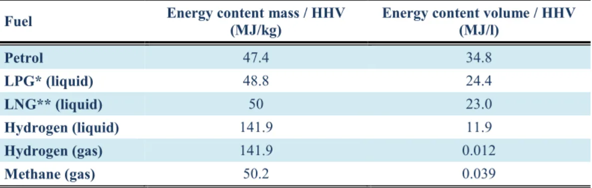
*At normal temperature and pressure. **Higher heating value and lower heating value. Table 2. Comparison of the energy content of liquid and gaseous fuels. (Scragg, 2009)
Fuel Energy content mass / HHV (MJ/kg) Energy content volume / HHV (MJ/l)
Petrol 47.4 34.8 LPG* (liquid) 48.8 24.4 LNG** (liquid) 50 23.0 Hydrogen (liquid) 141.9 11.9 Hydrogen (gas) 141.9 0.012 Methane (gas) 50.2 0.039
*Liquefied petroleum gas. **Liquefied natural gas.
It is clear from Table 2that both methane and hydrogen in the gaseous phase have low energy per unit volume but in hydrogen even in liquid state the energy per unit volume is still low. However, there are several disadvantages or complexities in storage and handling, the production, and flammability of hydrogen, which questions the adoption of hydrogen as an energy carrier (Hammerschlag & Mazza, 2005).
6
2.2 Hydrogen Applications
Hydrogen can be used for various applications covering many industries, including (Scragg, 2009; Mohammed, et al., 2011):
Petroleum and chemical industries, like fossil fuels processing, ammonia manufacturing and petrochemicals (hydrodealkylation, hydrodesulphurization and hydrocracking).
Hydrogenation agent to increase the level of saturated fats and oil.
Hydrodeoxygenation for oxygen removal and saturation of double carbon bonds.
Hydrotreatment/upgrading of bio-oils to transportation fuels.
Metal production and fabrication.
Shielding gas in welding methods such as atomic hydrogen welding.
Rotor coolant in electrical generators at power stations.
Filling gas in balloons and airships.
Energy storage technology.
Electronic industry.
Production and processing of silicon.
Pharmaceuticals.
Fuel for rocket propulsion.
Power generation with fuel cells.
7
2.3 Hydrogen Storage and Distribution
Hydrogen storage and transportation are closely linked together. Hydrogen can be distributed continuously in pipelines or batch wise by ships, trucks, railways or airplanes. All these batch transportation requires a storage system but also pipelines can be used as pressure storage tanks.
Hydrogen as a gas, in ambient conditions, occupies a large volume (11 m3/kg) for storage. Therefore, the main challenge in hydrogen storage is to reduce the volume of gas in equilibrium with the environment. The hydrogen molecule can be found in various forms depending on the temperature and the pressure shown in the phase diagram (Figure 1). At low temperature of -262°C, hydrogen is a solid with a density of 70.6 kg/m3 and at higher temperature of 0°C and pressure of 1 bar with a density of 0.09 kg/m3 hydrogen is a gas. A small area starting at the triple point and ending at the critical point exhibits the liquid hydrogen with a density of 70.8 kg/m3 at -253°C. And at ambient temperature hydrogen is a gas. (Züttel, 2007; Kauranen, et al., 2012)
Figure 1. Phase diagram for hydrogen. (Züttel, 2007)
Hydrogen can be stored as pressurized gas, liquefied hydrogen, in metal hydrides, in nanostructured/ porous material, in hydrogen-rich chemical or on the surface of
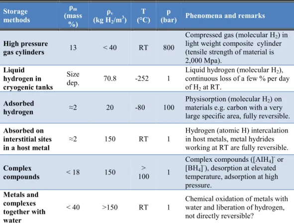
8 adsorption compounds (Krishna, et al., 2012; Züttel, 2007). At the moment, several kinds of technologies of hydrogen storage are available (Table 3).
The most common as well as the simplest method of hydrogen storage is compression of H2 gas at high pressure, which is possible at ambient temperature, and the in and out-flow are simple. It is commercially available, and the best known option is the use of C-fibre composite vessels (6–10 wt.% H2 at 350–700 bar). However, R&D issues include fracture mechanics, safety, need for compression energy, reduction of volume, and is costly. (Riis, et al., 2006; Krishna, et al., 2012)
Table 3. The six basic hydrogen storage methods and phenomena. (Züttel, 2007) Storage methods ρm (mass %) ρv (kg H2/m3) T
(°C) (bar) p Phenomena and remarks
High pressure
gas cylinders 13 < 40 RT 800
Compressed gas (molecular H2) in light weight composite cylinder (tensile strength of material is 2,000 Mpa). Liquid hydrogen in cryogenic tanks Size dep. 70.8 -252 1
Liquid hydrogen (molecular H2), continuous loss of a few % per day of H2 at RT.
Adsorbed
hydrogen ≈2 20 -80 100
Physisorption (molecular H2) on materials e.g. carbon with a very large specific area, fully reversible.
Absorbed on interstitial sites in a host metal
≈2 150 RT 1 Hydrogen (atomic H) intercalation in host metals, metal hydrides working at RT are fully reversible.
Complex
compounds < 18 150
> 100 1
Complex compounds ([AIH4]- or [BH4]-), desorption at elevated temperature, adsorption at high pressure. Metals and complexes together with water < 40 >150 RT 1
Chemical oxidation of metals with water and liberation of hydrogen, not directly reversible?
The gravimetric density ρm, the volumetric density ρv, the working temperature T and pressure p are listed. RT stands for room temperature (25°C)
Liquid hydrogen is also possible but 25% to 45% of the stored energy is required to liquefy the H2. In this method, the density of hydrogen storage is very high but hydrogen boils at about -253°C and it is necessary to maintain this low temperature or else the hydrogen will boil away, as well as bulky insulation is needed. This method is also commercially available and cryogenic insulate
9 dewars are mostly utilized, and similar to compressed H2 gas storage this method is also costly. (Riis, et al., 2006; Krishna, et al., 2012)
The third potential solutions for hydrogen storage are metal hydrides and hydrogen adsorption in metal-organic frameworks (MOFs) and carbon based systems. In metal hydride or solid state hydrogen storage, the powdered metal absorb hydrogen under high pressures (Krishna, et al., 2012). During this process, heat is produced upon insertion and with pressure release and applied heat, the process is reversed. Currently, these methods are in very early development stages with many R&D questions. Some of the R&D issues include, the weight of the absorbing material-mass of a tank would be about 600 kg compared to the 80 kg of a comparable compressed H2 gas tank, lower desorption kinetics, recharge time and pressure, heat management, life cycle cost, container compatibility and optimisation. (Riis, et al., 2006; Krishna, et al., 2012)
Currently, more popular is carbon absorption, which is the newest field of hydrogen storage. At applied pressure, hydrogen will bond with porous carbon materials such as nanotubes. The more focused ones are micro-porous zeolites, nano-porous MOFs and carbon-based materials, which is still in its developing phase. (Krishna, et al., 2012)
A key element of the overall hydrogen energy infrastructure is the distribution system that delivers hydrogen from its production point to an end-use device. Delivery system requirements necessarily vary with the production method and end-use applications. Hydrogen distribution through high-pressure cylinders and tube trailers has a range of 150–300 kilometres from the production facility. For long-distance distribution, hydrogen is usually transported as a liquid in super-insulated, cryogenic, over-the-load-tankers, railcars and barges. The transported liquid hydrogen is then vaporized for end uses. Hydrogen pipelines in Europe covers 1600 km whereas, 800 km in USA. Further information concerning the distribution of hydrogen can be found in the report presented by (Kauranen, et al., 2012). (Davis, et al., 2002; Kauranen, et al., 2012)
10 Melaina, et al. (2013) reviewed several key issues concerning blending hydrogen into natural gas pipeline networks that includes, benefits of blending, extent of natural gas pipeline network, impact on end-use systems, safety, leakage and downstream extraction. According to the study, blending hydrogen into natural gas pipeline networks at low concentrations is performed in the USA and some European countries. Relatively low concentrations of hydrogen, 5%–15% by volume, appear to be feasible with very few modifications to existing pipeline systems or end-use appliances. However, the assessed feasibility varies from location to location. Additionally, higher concentrations introduce challenges and requires modifications. They also estimated an extraction cost ranging from $0.3 - $1.3 per kg hydrogen for a 10% hydrogen blend, for a station with a pressure drop from 20 to 2 bars, depending upon the capacity and recovery rate. (Melaina, et al., 2013)
2.4 Raw Materials and Their Characteristics
For hydrogen to be renewable, it must be produced from renewable feedstock. In bio-hydrogen production, potential resources in feed-stocks include biomass, such as agricultural waste by-products, lingo-cellulosic products, such as wood and wood waste, waste from food processing and aquatic plants and algae, sewage sludge, agricultural and livestock effluents as well as animal excreta. Based on comprehensive literature studies (IEA, 2006; Mohanty, et al., 2014; Parthsarathy & Narayan, 2014), it can be assumed that if and once these resources are used under appropriate control, they would become one of the major sources of energy in the future.
Of all the renewables, biomass is a promising resource for producing environmentally friendly hydrogen. In fact, considering the CO2 penalty which may be imposed on fossil fuels, biomass has the potential to become cost competitive with fossil fuels. Biomass is a resource that is abundantly available in many parts of the world. The drawbacks of biomass are seasonal availability (agricultural feedstock), high feedstock and capital costs (Mahishi, 2006). Ni, et al. (2006) categorised a variety of biomass resources that can be used to convert into energy.
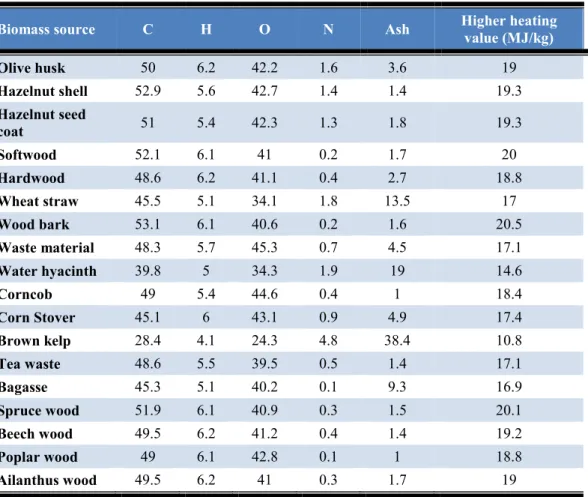
11 The use of any biomass for conversion to hydrogen energy is affected by the values of its physicochemical properties. These values not only determine the conversion process but in general the investment evaluation, as a whole. The understanding of those properties on the different biomass resources is essential before the conversion process can be considered. In general, the biomass properties that are of the greatest importance in energy processes are moisture content, ash content, volatile matter content, heating value, bulk density and alkali metal content (Table 4).
Table 4. Elemental analyses (wt.%, dry basis) and calorific values (HHV) of biomass samples. (Demirbas, 2009)
Biomass source C H O N Ash Higher heating value (MJ/kg)
Olive husk 50 6.2 42.2 1.6 3.6 19 Hazelnut shell 52.9 5.6 42.7 1.4 1.4 19.3 Hazelnut seed coat 51 5.4 42.3 1.3 1.8 19.3 Softwood 52.1 6.1 41 0.2 1.7 20 Hardwood 48.6 6.2 41.1 0.4 2.7 18.8 Wheat straw 45.5 5.1 34.1 1.8 13.5 17 Wood bark 53.1 6.1 40.6 0.2 1.6 20.5 Waste material 48.3 5.7 45.3 0.7 4.5 17.1 Water hyacinth 39.8 5 34.3 1.9 19 14.6 Corncob 49 5.4 44.6 0.4 1 18.4 Corn Stover 45.1 6 43.1 0.9 4.9 17.4 Brown kelp 28.4 4.1 24.3 4.8 38.4 10.8 Tea waste 48.6 5.5 39.5 0.5 1.4 17.1 Bagasse 45.3 5.1 40.2 0.1 9.3 16.9 Spruce wood 51.9 6.1 40.9 0.3 1.5 20.1 Beech wood 49.5 6.2 41.2 0.4 1.4 19.2 Poplar wood 49 6.1 42.8 0.1 1 18.8 Ailanthus wood 49.5 6.2 41 0.3 1.7 19
12
Chapter 3
3.1 Production Processes
The previous chapter described the basic properties, applications, up-to-date distribution and storage techniques of hydrogen, as well as the classification of raw materials for the production of bio-hydrogen gas. This chapter presents an overview of hydrogen production technologies from biomass. Section 3.2 explains the available thermochemical production processes from biomass: pyrolysis, liquefaction and gasification. Section 3.3 reviews the two different types of biomass technologies used for bio-hydrogen production: biomass gasification and supercritical water gasification. Similarly, Section 3.4 explains the available biological production processes from biomass, including direct- and indirect bio-photolysis, photo-fermentation and dark-fermentation. This section includes cost analysis of hydrogen production methods done by Mahishi (2006). For general understanding, basic description of some conventional methods are also explained in this section. The explained methods are steam methane reforming, partial oxidation, auto-thermal reforming and electrolysis. An overview of available thermochemical and biological technologies are presented in the latter sections. Four energy paths have been proposed for hydrogen production that can be obtained using renewable energy sources by Dincer (2012): thermal energy, electrical energy, biochemical energy and photonic energy. The electrical and thermal energy can be derived from renewable energies, such as solar, wind, geothermal, tidal, wave, ocean thermal, hydro, biomass, or from nuclear energy, or from recovered energy. The photonic energy is comprised in solar radiation only, which drives the processes like PV-electrolysis, catalysis photo-electro-chemical method and bio-photolysis for producing hydrogen. The biochemical energy is that stored in organic matter (in form of carbohydrates, glucose and sugars) and can be manipulated by certain microorganisms that can extract hydrogen from various substrates or it can be chemically converted to thermal energy. Biochemical energy can be assisted or not by solar radiation to
13 generate energy, depending on the case (viz. bio-photolysis or dark-fermentation). (Dincer, 2012)
This thesis mainly focuses on sustainable methods for hydrogen production from biomass (Figure 2). The main routes for hydrogen production using biomass are bio-chemical/ biological processes and thermo-chemical processes.
Figure 2. Hydrogen production routes from biomass.
Biomass to hydrogen conversion routes
Biological processes Thermochemical processes
Direct bio-photolysis Indirect bio-photolysis Biological water-gas shift reaction Photo-fermentation Dark-fermentation Gasification Pyrolysis Liquefaction Steam reforming Hydrogen gas Hydrogen gas Water Water-gas shift
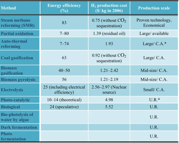
14 Mahishi (2006) calculated the economics of hydrogen (Table 5). The table lists the status of technology and the average cost of producing hydrogen during the year 2006. Efficiency is defined as the ratio of lower heating values of hydrogen in product gas to total energy supplied to the process (Equation 1).
Equation 1. η =ProductLHV
FeedLHV ∗ 100%
Despite the fact that the table shows the average energy efficiency, average hydrogen production cost and production scale; the reports, where the table is taken from, fails to clarify the meaning of this table leaving many questions unanswered. For instance, the feedstock used by all these methods are not mentioned; the sources of steam methane reforming (SMR) are not shown; fluctuations in energy efficiencies of partial oxidation and autothermal reforming is not explained as well as the size of production scale is not clear.
Table 5. Cost analysis of hydrogen production methods. Adapted from Mahishi (2006) & Parthsarathy & Narayan (2014)
Method Energy efficiency (%) H2 production cost
($/ kg in 2006) Production scale Steam methane
reforming (SMR) 83 0.75 (without Csequestration) O2
Proven technology, Economical Partial oxidation 7–80 1.39 (residual oil) Large/ available Auto-thermal
reforming 7–74 1.93 Large/ C.A.*
Coal gasification 63 0.92 (without CO2
sequestration) Large/ C.A. Biomass
gasification 40–50 1.21–2.42 Mid-size/ C.A.
Biomass pyrolysis 56 1.21–2.19 Mid-size/ C.A.
Electrolysis 25 (including electrical efficiency) 2.56–2.97 (Nuclear source) Small/ C.A.
Photo-catalytic 10–14 (theoretical) 4.98 U.R.*
Biological 24 (speculative) 5.52 U.R.
Bio-photolysis of
water by algae U.R.
Dark fermentation U.R.
Photo
fermentation U.R.
15
Conventional Technologies for Hydrogen Production
Steam Methane Reforming (SMR)SMR is the most widely used method for hydrogen production. SMR process is characterized by its high efficiency, favourable economics, proven technology, and is ideal for large scale hydrogen production.
Steam methane reforming produces hydrogen in the following three steps:
- Methane is first catalytically reformed at elevated temperature and pressure to produce synthesis gas (synthesis gas or syngas is a mixture of H2 and CO) as shown in the following reaction (Equation 2):
Equation 2. CH4+ H2O ↔ CO + 3H2
- A catalytic water gas shift (WGS) reaction is then carried out to combine CO and H2O to produce additional hydrogen as shown in the following reaction (Equation 3):
Equation 3. CO + H2O ↔ CO2+ H2
- The hydrogen product is then separated by adsorption
Methane is treated with high temperature steam to produce a mixture of H2, CO, CO2 and other impurities. The reaction is carried out in a reformer containing tubes filled with nickel catalyst at temperatures between 500–950°C and a pressure of 30 bars. Excess steam promotes the second step in the process, which is the conversion of syngas to the desired end product (hydrogen) via the water-gas shift reaction. The third step of separation is conventionally accomplished by pressure swing adsorption (PSA). PSA is a process used for the production of high purity hydrogen from steam methane reforming off-gas and refinery off-gas. (Mahishi, 2006)
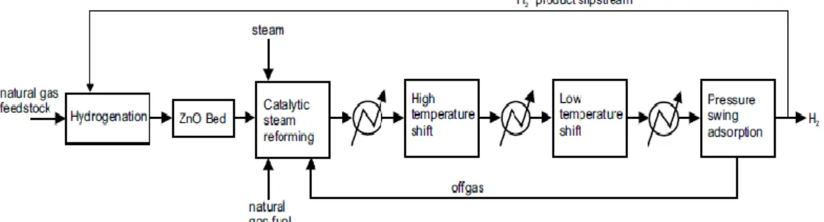
16 The classical method of producing hydrogen from natural gas is depicted in Figure 3. This method produces hydrogen via catalytic steam reforming of natural gas, which is a mature technology and is the route by which hydrogen is made today. The step by step description of the process can be followed in the report done by Spath & Mann (2001).
Figure 3. Hydrogen production from natural gas. (Spath & Mann, 2001) Partial Oxidation or Auto-thermal Reforming of Methane
Partial oxidation (POX) and Auto-thermal Reforming (ATR) are similar alternatives to SMR. The POX process partially oxidizes methane in a one-step reaction, while ATR combines partial oxidation and reforming reaction, catalytically reacting methane with a mixture of steam and oxygen. This differs from the steam methane reforming process which treats methane with steam only. Partial oxidation of methane produces a syngas mixture of CO and H2 as per the following reaction (Equation 4), which is then followed by WGS reaction (Equation 3):
Equation 4. CH4+12O2↔ CO + 2H2 (Mahishi, 2006) Electrolysis
Electrolysis uses electricity to dissociate water into diatomic molecules H2 and O2. An electric potential is applied across a cell with two electrodes containing a conducting medium, generally an alkaline electrolyte solution such as aqueous solution of potassium hydroxide (KOH). Electrons are absorbed and released at
17 the electrodes, forming hydrogen at the cathode and oxygen at the anode. Under alkaline conditions, this process may be described by the following reactions (Equation 5, Equation 6 and Equation 7):
Equation 5. Cathode: 2H2O + 2e−→ H
2+ 2OH− Equation 6. Anode: 2OH−→1
2O2+ H2O + 2e− Equation 7. Overall: H2O → H2+1
202
The net effect of this process is to produce hydrogen and oxygen by supplying only water and electricity. The theoretical voltage for the decomposition at atmospheric pressure and 25°C is 1.23 volts. At this voltage, reaction rates are very slow. Therefore, in practice higher voltages are applied to increase the reaction rates. However, this results in increased heat losses to the surrounding, decreasing the energy efficiency. The necessary voltage may be lowered by using catalysts or sophisticated electrode surfaces. Increasing temperature and pressure may also increase the efficiency at the cost of additional material needed to resist corrosion or higher pressures. (Mahishi, 2006)
18
3.2 Thermochemical Processes
This section reviews the available thermochemical processes for the production of hydrogen using biomass. As mentioned in the earlier section, the available thermochemical production processes from biomass involve pyrolysis, liquefaction and gasification.
3.2.1 Pyrolysis
Pyrolysis is the heating of biomass at a temperature of 400–600°C and close to atmospheric pressure in the absence of air to convert biomass into liquid oils, solid charcoal and gaseous components. Pyrolysis is further classified into slow and fast pyrolysis. Slow pyrolysis usually occurs at temperature between 400 and 450°C, with low heating rate of 1–5°C /s and high residence time (4–8 minutes). And fast pyrolysis usually occurs at temperature between 450–950°C, with the high heating rate of about 100–300°C/s and a very short residence time of about 1–5 seconds to produce high quality products.
The products of pyrolysis can be found in all gas, liquid and solid phases (Ni, et al., 2006):
(i) Gaseous products include mixture of (H2), CH4, CO, CO2 and other gases depending on the organic nature of the biomass for pyrolysis.
(ii)Liquid products include tar and oils that remain in liquid form at room temperature.
(iii)Solid products are char, which is almost pure carbon, and inorganic components such as ash and alkali metals from biomass
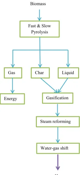
The typical product mass yield from woody biomass under slow pyrolysis conditions are about 30% liquid product, 35% gas and 35% char. Similarly, the mass yield for fast pyrolysis are about 70% liquid product, 15% gas and 15% char. The gaseous product can be used for providing heat for the pyrolysis reaction or for drying of the biomass.
The organic liquid and solid products can be processed for hydrogen production. The pyrolysis oil can be separated into two fractions based on water solubility.
19 These fractions can either be used separately or as mixtures for hydrogen production through gasification process. The material flow is illustrated in Figure 4. (Ni, et al., 2006)
Figure 4. Biomass to hydrogen based on pyrolysis with a co-products strategy. Adapted from Ni, et al. (2006)
3.2.2 Liquefaction
Water present in biomass poses negative effect on pyrolysis, as it requires high heat of vaporization. In general, pyrolytic liquefaction usually liquefies biomass suitably having < 40% of moisture contents. Water contents in tropical grasses can be as high as 80–85% or similarly ~90% for aquatic species. Biomass usually requires pre-processing to suit pyrolysis application, which is energy consuming
Biomass
Fast & Slow Pyrolysis Gas H2 Char Liquid Energy Gasification Steam reforming Water-gas shift
20 or/ and costly. One solution to handle high moisture contents in biomass can be hydrothermal liquefaction of biomass. (Akhtar & Amin, 2011)
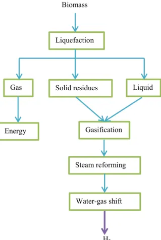
Liquefaction is a thermal conversion process where biomass is heated to 250– 350°C in water at a pressure of 5–20 MPa in the absence of air in order to obtain liquid fuel. Solvent or catalyst can be added depending on the process parameters and or product specifications. The liquid substances are mostly hydrocarbons and are also known as bio-oils. Like pyrolysis oil, liquefied oil can be either separated into two fractions based on water solubility, meaning that the water soluble fraction can be used for hydrogen production, or the mixture itself can be used for hydrogen production through gasification process (Figure 5). (Mohammed, et al., 2011; Akhtar & Amin, 2011)
Figure 5. An overview of biomass to hydrogen based on hydrothermal liquefaction. Biomass
Liquefaction
Gas
H2
Solid residues Liquid
Energy Gasification
Steam reforming
21
3.2.3 Gasification
Biomass gasification is a process by which either a solid or liquid carbonaceous material, containing mostly chemically bound carbon, hydrogen, oxygen, and a variety of inorganic and organic components, is reacted with air, oxygen, and/or steam to produce a primary gaseous product containing mostly CO2, H2, CO, CH4, H2O (g), and light hydrocarbons laced with volatile and condensable organic and inorganic compounds. Biomass can be gasified at high temperatures of above 750°C, during which the biomass particles undergo partial oxidation resulting in gas and charcoal production. Finally, the charcoal is reduced to form CO2, H2, CO and CH4. This conversion process can be expressed as (Equation 8):
Equation 8.
Biomass + heat + steam →
H2+ CO + CO2+ CH4+ light and heavy hydrocarbons + char. (Lin, et al., 2002; Ni, et al., 2006)
Figure 6 illustrates the general biomass gasification process. Solid biomass is pre-treated before gasification by drying and grinding whereas, liquid fuel from pyrolysis or liquefaction does not require similar pre-treatment procedures. In gasification stage, the solid/liquid biomass reacts with oxygen in high temperature to form synthesis gas. Gasification consists of drying, structure disintegration, pyrolysis as well as char combustion reaction of biomass feedstock. The gases produced can be steam reformed to produce hydrogen and this process can be further improved by water-gas shift reactions.
Biomass
Figure 6. Block diagram of biomass gasification process. (Patronen, 2011)
The gasification process is applicable to biomass having moisture content less than 35% because higher moisture content reduces the thermal efficiency (since heat is used to drive off the water and consequently this energy is not available for
Drying, Grinding/ Liquid fuel Gasification Steam reforming Water-gas shift H2
22 the reduction reactions and for converting thermal energy into chemical bound energy in the gas), and it is likely to gasify biomass in supercritical water condition. (Ni, et al., 2006; Patronen, 2011)
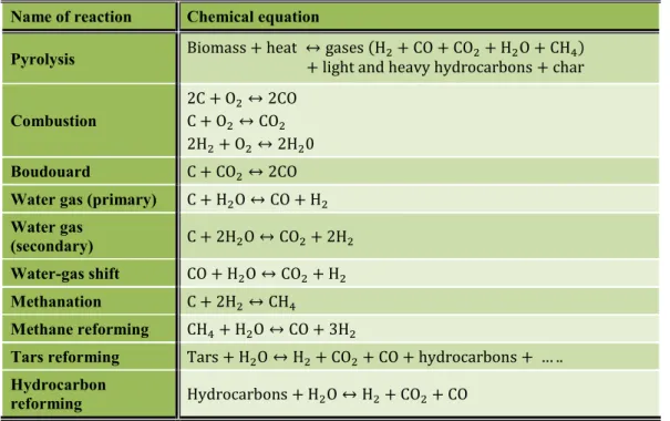
There are multiple reactions ongoing in the gasification process. Udomsirichakorn & Salam (2014) explain the mechanistic steps of biomass gasification in their review article. The important reactions of biomass gasification for the production of hydrogen are summarized in Table 6 (Udomsirichakorn & Salam, 2014).
Table 6. Important reactions in biomass gasification. (Mohammed, et al., 2011)
Name of reaction Chemical equation
Pyrolysis Biomass + heat ↔ gases (H+ light and heavy hydrocarbons + char2+ CO + CO2+ H2O + CH4) Combustion
2C + O2↔ 2CO
C + O2↔ CO2
2H2+ O2↔ 2H20
Boudouard C + CO2↔ 2CO
Water gas (primary) C + H2O ↔ CO + H2
Water gas
(secondary) C + 2H2O ↔ CO2+ 2H2
Water-gas shift CO + H2O ↔ CO2+ H2
Methanation C + 2H2↔ CH4
Methane reforming CH4+ H2O ↔ CO + 3H2
Tars reforming Tars + H2O ↔ H2+ CO2+ CO + hydrocarbons + … ..
Hydrocarbon
23
3.3 Thermochemical Technologies for Hydrogen Production from Biomass
This section reviews the two different types of biomass technologies used for bio-hydrogen production: biomass gasification and supercritical water gasification. Hannula (2009) reviewed and presented a selection of ongoing biomass gasification projects and related activities. The report mainly presents the currently used technologies for the production of transportation fuels, and these technologies could also be used for the production of renewable hydrogen.
3.3.1 Hydrogen from Biomass Gasification
During gasification process, solid biomass or liquid fuel from either pyrolysis or liquefaction is thermally decomposed to small quantities of char, liquid oil and high production of product gases under limited presence of oxygen. The product yields and the composition of gases are dependent on several parameters, including biomass types, gasifying agent, tar formation, ash formation, temperature, feedstock, particle size, heating rate, pressure, catalyst and reactor configuration.
All biomasses are mainly composed of cellulose, hemi-cellulose and lignin and their composition differs depending on biomass types. These components play a major role in the decomposition of biomass as larger composition of cellulose and lignin yield more gaseous products. This in turn increases the potential of hydrogen recovery from biomass. Many biomass types have been tried out so far to generate hydrogen, including pine sawdust, cedar wood, waste water sludge, palm oil waste, municipal solid waste and sawdust. (Mohanty, et al., 2014)
24
3.3.1.1 Factors Influencing Hydrogen Yield in Biomass Gasification Gasifying agent
In gasification reactions, gasifying agent is one of the issues that has significant influence on quantity and quality of the product gas. Generally, air, oxygen, steam as well as mixtures of these can be utilized as a gasifying agent; choice of which totally depends on the desired product gas composition (Table 7).
Table 7. Comparison between different gasification processes. (Parthsarathy & Narayan, 2014)
Air-blown gasification of biomass have a feasible application and has been developed actively for industrial purposes. However, this process technology produces low calorific value gases of 4–6 MJ/Nm3 and an 8–16.5 vol.% H2 (Ji, et al., 2009; Kim, et al., 2013; Udomsirichakorn & Salam, 2014; Galindo, et al., 2014). A better quality of product gas with medium calorific value (10–15 MJ/Nm3) can be produced using oxygen as a gasifying agent; but the process requires a pure oxygen supply which leads to simultaneous problem of cost and safety (Ni, et al., 2006; Saxena, et al., 2008; Mohammed, et al., 2011; Udomsirichakorn & Salam, 2014). Biomass steam gasification could produce medium calorific value gases (10–20 MJ/Nm3) and especially the product gas rich
Air gasification gasification Oxygen Steam gasification Heating value of
product gas
(MJ/Nm3) Low 4–6 High 10–15 High 15–20
Products CO, H2, Water, CO2, HC, Tar, N2 CO, H2, HC, CO2 H2, CO, CO2, CH4, light HC, tar
Average product gas composition H2–15%, CO–20%, CH4–2%, CO2–15%, N2–48%, H2:CO: 0.75 H2–40%, CO–40%, CO2–20%, H2:CO:1 H2–40%, CO–25%, CH4–8%, CO2–25%, N2–2%, H2:CO:1 Reactor temperature (°C) 900–1100 1000–1400 700–1200
25 in hydrogen content (30–60 vol.%) (Xiao, et al., 2011; Udomsirichakorn & Salam, 2014; Parthsarathy & Narayan, 2014; Wu, et al., 2014).In the open literature, there are many research works using these kinds of gasifying agents but this study mainly emphasizes the important aspects of the biomass gasification process relevant to hydrogen-enriched gas production.
Kim, et al. (2013) investigated air-blown gasification of woody biomass in a pilot scale bubbling fluidized bed gasifier aimed to produce product gas rich in hydrogen. Air was used as the gasifying agent as well as a fluidizing gas. The feed rates of biomass and air were controlled to change the equivalence ratio (ER) and vary the internal conditions. Changes in the biomass and air feed rates affected the product gas composition and temperature profiles in the gasifier. The concentration of syngas tended to increase as ER went from 0.27 to 0.19. The hydrogen concentration increased from 14.5% to 16.5%, carbon monoxide increased form 13.8% to 16.1% and CH4 from 4% to 5.3%. The total volume of the product gas decreased as ER was reduced. The concentration and calorific value (above 4.7 MJ/Nm3) of hydrogen are relatively higher than previous researches and it results from the configuration of the gasifier: longer free board and top fuel feeding.
Galindo, et al. (2014) presented an experimental evaluation of the quality of the product gas in a two-stage, air supply downdraft gasifier, referred to its tar and particle content for different operating conditions utilizing Eucalyptus wood (6 cm cubic shape) as feedstock. A slight increase in the gasifier efficiency was observed when the ER and the air ratio (AR) between the stages were carefully selected. For a total air flow of 20 Nm3/h and an air ratio between the two stages of 80%, the gasifier produced a fuel gas with low tar and particles content from 54.25 to 102 and 4 mg/Nm3, respectively compared to a tar and particles content of 418.95 and 146.03 mg/Nm3 obtained for a total air flow of 20 Nm3/h and an AR of 0%. The results confirmed that the use of a second stage air supply enables a reduction of 87% in tar yield and of 29.9% in the particle content of the gas. The product gases for this operational condition had a composition of 19.2 vol.% of CO, 1.3
26 vol.% of CH4, 17.14 vol.% of H2, 14.22 vol.% of CO2 and with an average LHV of 4.74 MJ/Nm3.
Chang, et al. (2011) experimentally investigated gasification of commercial cellulose and agricultural wastes (bagasse and mushroom), with air and mixture of air and steam in a fluidized bed for hydrogen production. They also investigated the influence of varied steam-to-biomass ratio (S/B). With S/B of 0.0 (i.e., no steam or only-air gasification), reaction temperature of 800°C and ER of 0.27, hydrogen content was found to be 13.5 vol.%. But once S/B increased to 1, hydrogen concentration raised to almost 20 vol.%.
Lv, et al. (2007) experimentally studied air and oxygen/ steam gasification of laboratory scale self-heated downdraft gasifier as the reactor using char as the catalyst for the characteristics of hydrogen production from pine wood (3 cm cubic shape). Air and steam/oxygen were utilized as the gasifying agents. The results indicated that biomass oxygen/steam gasification improves hydrogen yield compared to biomass air gasification depending on the volume of downdraft gasifier, and as well nearly doubles the heating value of fuel gas. For biomass oxygen/steam gasification, the maximum lower heating value of fuel gas reaches 11.11 MJ/Nm3 and under same operating conditions the maximum hydrogen yield of 45.16 g H2/ kg biomass is reached. The experimental and comparison results proved that biomass oxygen/steam gasification is more effective than biomass air gasification technique.
Udomsirichakorn & Salam (2014) studied, plotted and compared the effect of using different gasifying agents on hydrogen concentration in the product gas in their review article. The comparison showed that using pure oxygen as a gasifying agent rather than air gasification could produce the product gas with better calorific value, which is due to no dilution effect from nitrogen, and hydrogen content. And in case of partial amount of steam diluted in air or oxygen gasification, the resulting product is relatively richer in hydrogen composition. On the other hand, in the absence of both air and oxygen, pure steam gasification experiment shows higher hydrogen concentration. In the same study, it has been shown that the range of hydrogen content is higher in case of gasifying with pure
27 steam compared to the mixture of steam and oxygen. The reason for higher hydrogen content being the phenomenon of higher hydrogen content resulting from the decomposition of water, in the form of steam, added to the thermochemical conversion of biomass.
Although a direct comparison of hydrogen concentration and yield using different gasifying agents is not possible due to variation of many different operating conditions, still the review results provide a general insight into the influence of different gasifying agents.
Tar formation
Another major issue in biomass gasification is to deal with the tar formation that occurs during the process (Ni, et al., 2006). The undesirable tar may cause the formation of tar aerosols and polymerization to a more complex structure, which is not favourable for hydrogen production through steam reforming. Additionally, tar formation causes catalyst deactivation, operation interruption, and the production of carcinogenic elements. The two tar removal technologies are internal treatment in the gasifier (primary methods) and cleansing the heated gas after gasification (secondary methods). Primary methods that are available to minimize tar formation are proper design of gasifier, proper control and operation and additives/catalysts. Also the operation parameters, such as temperature, gasifying agent and residence time play vital role in formation and decomposition of tar. (Ni, et al., 2006; Pereira, et al., 2012)
Pereira, et al. (2012) studied and compared several experimental papers (Sun, et al., 2009; Meng, et al., 2011; Min, et al., 2011; Michel, et al., 2011) and concluded that the total tar content produced from biomass gasification depends not only on temperature but also on other parameters.
Many chemical substances have been proposed to enhance tar removal, since the removal of tars and the reduction of methane content increase the economic viability of the biomass gasification process. Mohammed, et al. (2011) suggest the use of three categorized groups of catalysts, which includes: (1) naturally occurring catalysts such as dolomite and olivine; (2) alkali metals such as KOH,
28 K2CO3, KHCO3, Na2CO3, CsCO3, KCl, ZnCl2 and NaCl; and (3) nickel-based catalysts, which have been evaluated for tar reduction in syngas. The main catalysts for tar reforming are listed in Table 8 (Mohammed, et al., 2011).
Table 8. Main catalysts for tar reforming. (Mohammed, et al., 2011)
Nickel-based catalysts are reported to be very effective for two different purposes: (1) in reducing tar; and (2) in decreasing the quantity of nitrogenated compounds such as ammonia. Although this provides satisfactory catalytic activity, nickel-based catalysts are expensive, gets easily deactivated, and are poisonous at high temperature.
According to Pereira, et al. (2012), natural dolomite is the most popular catalyst since it is easily available, inexpensive, disposable, and can significantly reduce the tar content of the syngas. A major problem with using dolomite is its deactivation due to the quick calcination in the gasifier as dolomite is a soft and fragile material that erodes easily, generating a raw gas with a high particulate content. They reviewed several studies and concluded that olivine is mechanically stronger than dolomite. One of their reviewed articles (Corella, et al., 2004) reported that although olivine was shown to be 1.40 times less effective for in-bed tar removal than raw dolomite, it generated four to six times fewer particulates in the gasification gas than dolomite. Their second reviewed article (Michel, et al.,
Catalyst type Representative catalysts Main advantages Technical challenges Maturely occurring catalyst Dolomite Olivine Clay Zeolite
Cheap Moderate reforming efficiency Easily eroded and broken
Alkali metals and salts KOH KHCO3 K2CO3 NaCO3 1. High reforming efficiency 2. Increased amount of hydrogen in syngas
Increased plugging and deactivation of other metal catalysts at a high temperature
Stable metal with oxide support NiO/Al2O3 Ni/CeO2/Al2O3 1. High reforming efficiency 2. Increased amount of hydrogen in syngas
Stable metals are expensive Metals are easily deactivated by coke, poisoned by H2S and sintered by ash melting Require hot-water-resistant support materials
29 2011) investigated the gasification of Miscanthus X Giganteus (a perennial warm-season Asian grass) in a fluidized bed reactor with the presence if Ni/olivine based catalysts. The results showed that the addition of NiO to olivine catalyst was efficient for reducing tar. And the third study (Rapagnà, et al., 2011) carried out steam gasification of biomass in a fluidized bed reactor using a 10 wt.% Fe/olivine catalyst and found that the studied catalysts reduced naphthalene and toluene by 48% and 59%, respectively.
Along with dolomite and olivine other effective catalysts include, olive kernel, activated carbon, methyl hexadecanoate and paraxylene, bed-material (olivine) coating, and addition of acetylene and hydrogen flames into the blend of gases containing toluene. (Pereira, et al., 2012)
Ash formation
Another problem of biomass gasification is the ash formation containing large quantities of inorganic elements such as alkali metals (K, Na), alkali earth metals (Ca, Mg), silicon, chlorine, and sulphur, as their main constituents. This ash formation may cause deposition, sintering, slagging, fouling, high temperature corrosion and agglomeration; leading to uneconomical operation or even to a shut-down of the plant. In order to resolve these problems, fractionation (Arvelakis & Koukios, 2002) and leaching (washing) (Jenkins, et al., 1996; Arvelakis, et al., 2001) can be employed to reduce ash formation inside the reactor. Fractionation being effective for ash removal might deteriorate the quality of the remaining ash whereas, leaching can remove inorganic fraction of the biomass as well as improve the quality of the remaining ash, but it is a quite expensive process step since large quantities of biomass need to be handled, resulting in large amount of wastewater, extensive energy consumption in drying and large investments due to the large size of systems.. Garcı́a-Ibañez, et al. (2004) reported gasification of leached olive oil waste in a circulating fluidized bed reactor for gas production that demonstrated the feasibility of leaching as a pre-treatment technique. (Ni, et al., 2006)
30 A number of efforts have been made by researchers to test hydrogen production from biomass gasification with various biomass types and at various operating conditions, as listed in Table 9.
31
Table 9. Investigations on biomass gasification for hydrogen production.
Reactor Biomass Gasifying agent Temperature (°C) Catalyst H2 content
(Vol.%) References
Fluidized bed Pine, eucalyptus and holm-oak steam 700–900 Not used 21–45 (Franco, et al., 2003)
Fluidized bed α- cellulose Steam and air 750–950 Not used 13.50–18.56 (Chang, et al., 2011)
Fluidized bed Pine sawdust, wood chip and cereal straw Steam 650–780 Not used 59 @ 750 °C (Herguido, et al., 1992)
Fluidized bed Rice hull Steam 700–800 Not used 32.8–42.62 (Boateng, et al., 1992)
Fluidized bed Spruce wood Air 780 Quartize Olivine 31 (Miccio, et al., 2009)
Updraft gasifier Rice straw Air 700–850 Alumina-silicate bed and MgO 6–10 (Calvo, et al., 2012)
Stainless steel
cylinder tube Sawdust Steam 600,670,710 CaO (sorbent) 54.43 (Acharya, et al., 2010)
Semi-batch type Waste water sludge Steam 900 Not used _ (Nipattummakul, et al., 2010)
Fixed bed Bagasse Oxygen and steam 800 Ni-Al2O3 51.7 (De Filippis, et al., 2004)
Fixed bed Municipal solid waste Steam 900 Calcined dolomite 53.22 (He, et al., 2009)
32
3.3.2 Hydrogen Production from Gasification in Supercritical Water
Supercritical water gasification (SCW) is another gasification technology for hydrogen production, glucose and cellulose being mainly utilized biomass feedstock in laboratory scale. Under normal conditions, water exists in three states, and when the pressure and temperature of water is subjected to supercritical state (22.1 MPa and 374°C), its gas and liquid phase becomes miscible. At this point water acts as an oxidant and when biomass reacts with supercritical water the oxygen molecules of water are transferred to carbon atoms of biomass. The properties of water displayed beyond critical point (supercritical) plays significant role for chemical reactions. The hot compressed water molecules can participate in various elementary reaction steps as reactant, catalysts as well as medium. The overall reaction can be written as (Equation 9): (Mohammed, et al., 2011; Parthsarathy & Narayan, 2014)
Equation 9. 2C6H12O16+ 7H2O → 15H2+ 9CO2+ 2CH4
CO formed in intermediate reaction step undergoes water-gas shift reaction and produces CO2 and hydrogen. The hydrogen atoms of water and biomass is set free and thus, hydrogen is generated.
Mohammed, et al. (2011) reports that reaction temperature (500–700°C) will have a strong effect on yields and gas compositions, whereas pressure above the critical has little effect on the extent of gasification or the composition. Studies have been conducted with and without the use of catalysts and the common catalysts include activated carbon, transition metal and alkali salts.
Alkali metal catalyst is known for its effectiveness in improving the water-gas shift reaction during the reaction process, but also may cause corrosion, plugging or fouling of equipment. Transition metal catalysts (Ni, Pt, and Rh) are supposedly known for improving the reaction by accelerating the steam reforming reaction, methanation reaction and C–O and C–C and so on. Additionally, activated carbon catalyst is also effective during water-gas shift reaction and methanation reaction. It is concluded that these catalysts can effectively increase
33 the activation energy in SCW reaction but on the other hand, dozens of studies have confirmed the instability of most catalysts. (Guo, et al., 2010)
A summary of hydrogen production via gasification in supercritical water researches with different operating conditions, catalysts and reactors is tabulated in Table 10.
34
Table 10. Gasification in supercritical water of different biomass for the production of hydrogen.
Reactor Biomass Pressure (MPa) Temperature (°C) Catalyst H2 yield References Autoclave Glucose 24.5 400 Ni/CeO2–γAl2O3 Ni/γAl2O3 12.7 moles H2/ kg feed (Lu, et al., 2010)
Batch micro-reactor Glucose 15–25 340–380 R-nickel 6 mmol H2/ g feed (Azadi, et al., 2009; Azadi, et al., 2009)
Packed bed Glucose 28 575–725 Ni/activated carbon 2.45 moles H2/ mole feed (Lee, 2011)
Tubular Lignin 37.1 400 RuCl3/TiO2 _ (Yamaguchi, et al., 2008)
Tubular Paper sludge black liquor 25 500–650 Alkali salts 24 moles H2/ kg feed (Rönnlund, et al., 2011)
High pressure
autoclave Cellulose 24-26 450–500
K2CO3
Ca(OH)2 8.2 moles H2/ kg feed (Guan, et al., 2007)
Tubular Cellulose sawdust 27 500 CeO2, Ru/C (CeZr)xO2 4 g H2/ 100 g feed (Hao, et al., 2005)
35
3.4 Biological Processes
This section reviews the biological hydrogen production processes, which can be classified into five different mechanisms: (i) direct bio-photolysis, (ii) indirect bio-photolysis, (iii) photo-fermentation, (iv) dark-fermentation and (v) biological water-gas shift reaction.
Direct bio-photolysis, also known as bio-photolysis, is associated with plant-type photosynthesis as it utilizes light energy to split water for hydrogen formation. It occurs among certain green algae under anaerobic conditions. Indirect bio-photolysis typically involves cyanobacteria that utilize carbohydrate energy stored from photosynthesis to generate hydrogen from water. Photo-fermentation is the conversion of organic compounds to bio-hydrogen, occurring among various groups of photosynthetic bacteria via series of biochemical reactions. Dark-fermentation, more generally known as Dark-fermentation, is a process occurring in dark conditions in which anaerobic bacteria break down carbohydrates to produce hydrogen, among the other by-products (namely CO2). Biological water-gas shift reaction involves oxidation of CO to CO2 by utilizing enzymes rather than metals to catalyse the process. The feeds for biological hydrogen are water for photolysis and biomass for fermentation processes. (Holladay, et al., 2009; Brentner, et al., 2010; Azwar, et al., 2014)
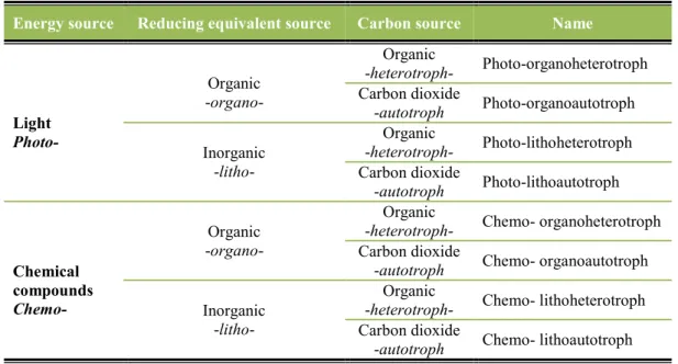
36 Energy source for these processes could either be light (photo-) or chemical compounds (chemo-). Organisms able to use chemicals as electron donors are called chemotrophs, whereas organisms that uses light as their energy source are called phototrophs. Table 11 presents the different types of trophs based on their reducing equivalent source and carbon source. (Madigan, et al., 2009)
Table 11. Microbiological division of organisms based on energy sources. (Madigan, et al., 2009)
Energy source Reducing equivalent source Carbon source Name
Light Photo- Organic -organo- Organic -heterotroph- Photo-organoheterotroph Carbon dioxide -autotroph Photo-organoautotroph Inorganic -litho- Organic -heterotroph- Photo-lithoheterotroph Carbon dioxide -autotroph Photo-lithoautotroph Chemical compounds Chemo- Organic -organo- Organic
-heterotroph- Chemo- organoheterotroph Carbon dioxide
-autotroph Chemo- organoautotroph Inorganic
-litho-
Organic
-heterotroph- Chemo- lithoheterotroph Carbon dioxide
-autotroph Chemo- lithoautotroph
Table 12 provides a summary of previously explained mechanisms, including organisms, reactions and key enzymes.