Technology (IJRASET)
©IJRASET 2015: All Rights are Reserved
933
FPGA Implementation of Efficient
Window-Architecture Design Using Completely Scaling –
Free CORDIC Algorithm
Rashmi.K.L1, Rama Murali Krishna.P.G2, B.E, M.Tech, Asst.professor
Department of Electronics and Communication Engineering (VLSI design), KVG College of engineering, sullia, D.K, Visvesvaraya Technological University, Belgaum
Abstract- one of the most important step in spectral analysis is filtering, this paper presents an FPGA implementation of window function using CORDIC (co-ordinate rotation digital computer) to minimize area-delay product. Co-ordinate rotation digital computer (CORDIC) is an arithmetic technique, which performs two dimensional rotations using simple hardware components. This algorithm can be used for computing a wide range of functions including certain trigonometric, hyperbolic, linear and logarithmic functions, and can evaluate elementary functions such as cosine, sine, arctangent, sinh, cosh, tanh, ln, &exponential. Here FPGA implementation of various window functions using CORDIC algorithm by replacing linear CORDIC with multiple shift-add network and conventional circular CORDIC processor by a completely scaling free CORDIC processor to improve the area-time efficiency.
Keywords: CORDIC, field programmable gate array (FPGA), completely scaling-free , micro-rotation., pipelined.
I. INTRODUCTION
CORDIC(Co-Ordinate Digital Computer) algorithm is a well known iterative technique to perform basic arithmetic operations which includes computation of trigonometric functions, estimation of vector magnitude etc . Commonly many hardware architecture are available for realizing FFT but the same is not true for window-architectures. The conventional hardware implementation of window functions uses lookup table which leads to area and time complexity with increase in word-length, in this they do not allow user defined variations in window – length. CORDIC is a very well-known algorithm because of its versatility and simple hardware implementation that only needs add & shifts operations. Though they allow user defined variations in window-length, latency is a major problem. By using two CORDIC processor in series, the overall latency can be hampered. In this paper, replacing conventional linear CORDIC processor with the multiple optimized shift-add network and conventional circular CORDIC with completely scaling-free CORDIC processor reduce the pipelining depth & area of the existing design which reduces the latency. The rest of this paper is organized as follows:- section II deals with the different window functions, conventional CORDIC algorithm and completely scaling-free CORDIC algorithm. Section-III deals with proposed architecture. Section-IV deals with FPGA implementation, section –V details the results, section-VI conclude the paper.
II. BRIEF REVIEW OF THE CONVENTIONAL AND THE SCALING-FREE CORDIC
In signal processing, a window function is a mathematical function that is zero-valued outside of some chosen interval. For instance, a function that is constant inside the interval or zero elsewhere is called a rectangular window, which describes shape of its graphical representation. When another function or waveform/data-sequence is multiplied by a window function, the product is also zero-valued outside the interval; all that is left is the part where they overlap. There are different windows like hanning, hamming, blackman, kaizer etc. the windows can be selected based on spectrum or spectral characteristics.
The equation for the hanning & hamming windows are-
=0.5+0.5cos( )
Where N is the length of the window.
Technology (IJRASET)
©IJRASET 2015: All Rights are Reserved
934
Where β=1-α.
The constant is approximated to α= , β= which achieves the side lobe cancellation.
A. Conventional CORDIC algorithm
CORDIC algorithm is based on rotation of vectors in two-dimensional coordinate space using simple shift & add operation. CORDIC algorithm can operate in two modes namely: rotation & vectoring. In rotation mode, the objective is to convert polar coordinate of a vector into Cartesian where as vice versa in vectoring mode through a series of iterations. The rotation trajectory can be linear, circular or hyperbolic depending upon the requirement. It consists of two operating modes, the rotation mode (RM), where a vector is [ , ] rotated by an angle (θ) to obtain [ , ] and the vectoring mode (vM) where CORDIC algorithm
computes length r, angle θ towards the x-axis of a vector[ , ] . The coordinates of two vectors VA [ , ] and VB [ , ]
separated by an angle θ which is related as:
[ ] = R [ ] , R= −
The key concept for realizing rotation using CORDIC algorithm is to express the desired rotation angle ‘θ’ as an aggregation of pre-defined elementary angle pre-defined as:
= .
Where [ , ] is the final vector & ‘θ’ is the target angle of rotation and is expressed as the summation of ∝= 2 , where ‘b’ is the word length and {1,−1} is known as the direction of the vector rotation for its iteration.
The rotation matrix R requires, determining sine & cosine term, simplifies the rotation matrix by converting multiplication operations to shift, as the tangent of elementary angles are defined in negative power of two.
1 −2
2 1 , =
The rotation matrix = 1 − 2
2 1
Where = -1 for clockwise rotations & = 1 for anticlockwise rotations. In its original form , CORDIC algorithm suffers from major disadvantages like, scale-factor compensation , latency and optimal identification of micro-rotations.
B. Completely – scaling free CORDIC algorithm
In completely scaling-free CORDIC (coordinate rotation digital computer) algorithm, the coordinate rotation matrix is derived using
3 order of approximation of Taylor series of sine and cosine function.
Taylor series is used for expansion of sine &cosine functions to avoid scaling operation. Suggests a generalized sequence of micro-rotation to have adequate range of the Taylor series.
To facilitate shift-add implementation of rotation matrix, the Taylor series coefficient 3! Is approximated as 2 .
For = 2
= 1−2
( ) −(2 −2 ( ))
Technology (IJRASET)
©IJRASET 2015: All Rights are Reserved
935
The elementary are defined as
= 2
Where is the number of shifts for the iteration
Depending on the order of Taylor series approximation, the largest elementary angle & the (basic-shift) is used to realize the coordinate rotation matrix. = 2 and = 0.25 radians for 3rd order approximation. Any rotation angle, is realized by using n1 iterations of and n2 iterations corresponding to other elementary angles , such that, the total number of iterations (n1+n2) is always a constants.
n2 iterations
= 1. +
Where > and n n1+ n2
To realize any rotation angle in the range [0,π/4], total of seven iterations are required which is extended to the entire coordinate space using the octant wave symmetry of sine and cosine function.
III. ARCHITECTURE FOR IMPLEMENTING WINDOW FUNCTIONS
In this section, focusing on the pipelined architecture to generate window functions. The length of the window function is selected by the user at the run time. Currently, the architecture implements the hamming window, but with slight modifications it can be extended to other window functions as well. In this proposed architecture, the output bit width is set to 16-bits.
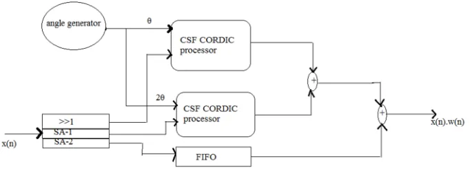
Fig-1 shows the block diagram for generating hamming window function.
The circuit consists of angle generator,(WCM) window coefficient multiplier, CSF CORDIC processor(CCP), FIFO. The angle
[image:4.612.163.504.524.648.2]generator generates θ & 2θ two angle value required for hamming window function. window coefficient multiplier(WCM ) multiplies the input signal samples with the window constants using an shift-add network.CCP is used for generating the cosine term in window function. FIFO is used for proper synchronization between window coefficient having cosine terms and constants.
Fig 1: block diagram for generating hamming function
A. Completely scaling free CORDIC processor(CCP)
Technology (IJRASET)
©IJRASET 2015: All Rights are Reserved
936
[image:5.612.140.479.151.426.2]of three blocks ( I)the coordinate calculation unit, (II) micro-rotation sequence generator(MRSG) ,(III) the shift-index calculation. The coordinate calculation unit implements using shift-add implementation. The shift- index calculation computes the necessary shifts, required by the calculation unit. The micro-rotation is as shown in the figure-3
[image:5.612.138.480.154.271.2]Fig 2: pipeline architecture
Fig 3: micro-rotation sequence generator(MRSG)
.The micro rotation sequence generator selects appropriate elementary angle for the current CORDIC iteration. Using refined elementary angles, the micro-rotations can be identified using the circuit shown in fig-3. It consists of a priority encoder and a reset circuitry. The input to the micro rotation sequence generator is the rotation angle θ [N-1:0] , where N is the word length. The priorities of the encoder are hooked in the reverse order with
Having the highest priority and the least. The reset circuitry resets a bit of the input rotation angle to generate the residue angle for next CORDIC iteration. Since, the micro rotation sequence generates the shift-index for one CORDIC iteration, it is required in every stage of the CORDIC pipeline. Even though, the coordinate calculation unit of the proposed completely scaling free CORDIC is more complex than the conventional CORDIC ,the overall gate count of the proposed window architecture is reduced.
B. Window coefficient multiplier (WCM)
WCM unit multiplies the input samples with the hamming window coefficients(α, β) . In radix-2 representation systems,
multiplication with 0.5 is equivalent to single shift. Therefore, multiplication with α=0.5 is realized using a hardwired shifter for
hamming window, the coefficient α is represented in 16-bit fixed point format is 0010_0010_1000_0000 and the coefficient β is
represented 0001_1101_1000_0000. The complexity of the WCM unit is equivalent to six 16-bit adders, as hardwired shifters do not incur any hardware costs.
C. Angle generator
Technology (IJRASET)
©IJRASET 2015: All Rights are Reserved
937
Δθ = ( ) For N=2 , Δθ=
⇒Δθ= ). (1−2 )
Using binomial theorem (B.T.), we simplify (15c) to the following:
using B.T.(1− ) =1+x+ + + +⋯
B.T. of =⇒
(1−2 ) =11 + 2 + 2 +………….
Δθ= + +
⇒Δθ = (2π >>M) + (2π >>2M) + (2π >>3M).
Generally in most signal processing applications, not less than 16-point DFT is used which implies N ≥ 16 and M ≥ 4. Therefore, only three terms of binomial expansion are sufficient for 16 bit accuracy as follow
fourth term of B.T.Δθ4=
=⇒Δθ4 = 2π >> 4M.
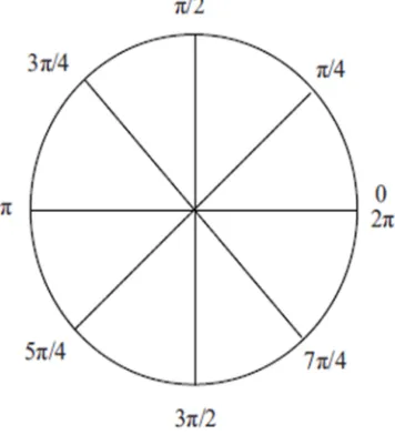
[image:6.612.205.383.445.641.2]The angles in the windowing function are uniformly distributed over the entire coordinate space. The CCP unit handles angles in the range of [0, π/4]. Therefore, the TGU divides the entire coordinate space into octants, so that the input angle to CCP always lies in the range [0, π/4]. The octants are distinguished as shown in Figure3; the angle generator also generates signals for proper octant mapping of values generated by CCP. The TGU requires three 16 bit adders, two barrel-shifters and one encoder.
Fig 4 : Mapping Of Coordinate Space Into Octants
Technology (IJRASET)
©IJRASET 2015: All Rights are Reserved
938
Fig :3 compares the hamming window generated using the proposed processor with that of MATLAB inbuilt function hamming () for N = 16
amplitude
[image:7.612.41.571.131.392.2]sample
fig 5: Matlab output to generate sine wave
purple line- Matlab hamming yellow line-proposed.
IV. FPGA IMPLEMENTATION
The proposed architecture is coded in verilog, simulated in Xilinx ISE 12.2i design suite to be mapped on Xilinx virtex 2pro(x C2VP50-6FF1148) device. For 16 bit implementation, the proposed design consumes 960 slices and 1920 4-Input LUTs, with a maximum operating frequency of 101.23 MHz. The total delay of 8.48 nsec is distributed as 76.9% logic delay and 23.1% route delay. The total gate count of the proposed design is 16800.
A. Area and latency comparison:
Table III compares the area and latency of the proposed design with the existing architecture variants. The area of conventional circular CORDIC processor is calculated using Xilinx CORDIC IP. It is optimized for circular CORDIC computation with maximum pipelining for 16-bit word length. The complexity of 16-bit scaling free CORDIC is computed to be equivalent to 1000 1-bit full adders and gate count is 20122 and 597 1-1-bit registers, which requires 16776 gates for implementation. The complexity of the 16-bit linear conventional CORDIC is equivalent to 512 1-bit full adder and 768 1-bit register, which amounts to 12288 gates. The other units like angle generator unit, FIFO, adders required for realizing the window processor are common for the proposed as well as the existing design.
B. Latency
Technology (IJRASET)
©IJRASET 2015: All Rights are Reserved
939
new redesigned- CORDIC pipeline is 7 stages long.
C. Delay
[image:8.612.88.526.206.421.2]The delay is the time required to generate one set of window coefficients for window length of N when the design is operating at the max clock frequency. The critical path for the proposed design is the angle generator. By using angle generator the existing design using conventional circular CORDIC and scaling free circular CORDIC is designed. The angle generator for the proposed design and the existing design using the conventional circular CORDIC and the scaling free circular CORDIC generates the angle in the range[-π/4, π/4], the clock frequency for the existing design is 101.983MHz and for other designs including the proposed design is 107.008MHz.
Table I: FPGA features used in proposed architecture Top level source type HDL
Preferred language Verilog Family Spartan-3 Device Xa3s100 Package vQg100 Speed -4 Simulator Isim
Table II: summary report of the CSF CORDIC Area 960 slices, 1920 LUTs Latency 7 pipelining
Maximum clock frequency 107.008MHz
Delay 8.48ns
[image:8.612.146.504.452.699.2]Total gate-count 16800 Type of architecture Pipelined Window size Variable
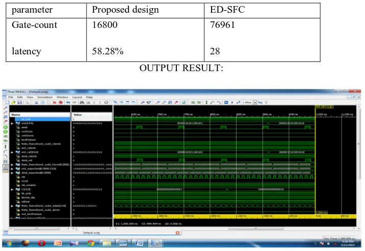
Table III: area-latency comparison of proposed window-architecture with existing architecture
parameter Proposed design ED-SFC Gate-count
latency
16800
58.28%
76961
28 OUTPUT RESULT:
Technology (IJRASET)
©IJRASET 2015: All Rights are Reserved
940
V. CONCLUSION
In this paper, an area-time efficient CORDIC based processor for computing window function. Currently the architecture implementing the hamming window function, with slight modification, can be extended to other window functions as well. Proposed design is of word length 16 bit. Computing the window function by saving the area, reduces the latency and optimizing the delay for maximum extent. In the existing design, replacing the linear CORDIC processor with multiple shift-add units and the circular conventional CORDIC processor with the completely scaling-free CORDIC processor.
REFERENCES
[1] K. K. Parhi, VLSI Digital Signal Processing Systems, JohnWiley & Sons, 1999.
[2] J. G. Proakis and D. G. Manolakis, Digital Signal Processing Principles, Algorithms and Applications, Prentice Hall, 3rd edition, 2006.
[3] A.M. Despain, “Fourier transform computers using CORDIC iterations,” IEEE Transactions on Computers, vol. 23, no. 10, pp. 993–1001, 1974.
[4] T. Sansaloni, A. P´erez-Pascual, and J. Valls, “Area-efficient FPGA-based FFT processor,” Electronics Letters, vol. 39, no. 19, pp. 1369–1370, 2003.
[5] M. Ayinala, M. Brown, and K. K. Parhi, “Pipelined parallel FFT architectures via folding transformation,” IEEE Transactions on Very Large Scale Integration (VLSI) Systems, vol. 20,
no. 6, pp. 1068–1081, 2011.
[6] K. C. Ray and A. S. Dhar, “CORDIC-based unified VLSI architecture for implementing window functions for real time spectral analysis,” IEE Proceedings: Circuits, Devices and Systems, vol. 153, no. 6, pp. 539–544, 2006.
[7] K. C. Ray and A. S. Dhar, “High throughput VLSI architecture for Blackman windowing in real time spectral analysis,” Journal of Computers, vol. 3, no. 5, pp. 54–59, 2008.
[8] J. E. Volder, “The cordic trigonometric computing technique,” IRE Transactions on Electronic Computers, vol. 8, no. 3, pp. 330–334, 1959.
[9] J. S. Walther, “A unified algorithm for elementary functions,” in Proceedings of the 38th Spring Joint Computer Conferences, pp. 379–385, Atlantic City, NJ, USA, 1971.
[10] P. K. Meher, J. Valls, T. B. Juang, K. Sridharan, and K. Maharatna, “50 years of CORDIC: algorithms, architectures, and applications,” IEEE Transactions on Circuits and Systems I, vol. 56, no. 9, pp. 1893–1907, 2009.
[11] J. O. Smith III, Spectral Audio Signal Processing,W3K, 2011.
[12] T. B. Juang, S. F. Hsiao, and M. Y. Tsai, “Para-CORDIC: parallel CORDIC rotation algorithm,” IEEE Transactions on Circuits and Systems I, vol. 51, no. 8, pp. 1515–1524, 2004.
[13] K. Maharatna, S. Banerjee, E. Grass, M. Krstic, and A. Troya, “Modified virtually scaling-free adaptive CORDIC rotator algorithm and architecture,” IEEE Transactions on Circuits and Systems for Video Technology, vol. 15, no. 11, pp. 1463–1474, 2005.
[14] J. Vankka, Digital Synthesizers and Transmitters for Software Radio, Springer, Dordrecht, Netherlands, 2005.
[15] K. Kota and J. R. Cavallaro, “Numerical accuracy and hardware tradeoffs for CORDIC arithmetic for special-purpose processors,” IEEE Transactions on Computers, vol. 42, no. 7, pp. 769– 779, 1993.


![The quality of ‘egusi’ melon [(Citrullus lanatus Thunb.) Matsum and Nakai] seeds derived from fruits harvested at different growth stages and at different positions on the mother plant](data:image/gif;base64,R0lGODlhAQABAIAAAP///wAAACH5BAEAAAAALAAAAAABAAEAAAICRAEAOw==)