Technology (IJRASET)
A Study on Error Coding Techniques
Deepika S S1, Ashwin kumar2 Gurusiddayya H3
1
M.Tech in VLSI & Embedded Systems, 2,3Assistant Professor, Dept.Electronics & Communication Engineering Sahyadri College of Engineering & Management, India
Abstract: There are numerous error coding techniques in the field of digital communication. They are utilized to detect/correct single bit or multiple bit errors. In this paper commonly used codes like Hamming codes, CRC and Reed-Muller codes are compared based on encoding and decoding methods. The designs are also compared based on the implementation in Xilinx Spartan FPGA device. Hamming codes are relatively easy to implement and the throughput of this code is high. Hamming codes are single error correcting and double error detecting (SECDED) codes. Applications include in fields like DRAM memory chips, satellite communications.
Keywords – Burst error, check bits, error coding, Hamming distance, linear block code.
I. INTRODUCTION
When data is transmitted from source to destination errors are likely to be introduced in the transmission medium due to environmental interference and physical defects. The detection and correction of errors is called error coding. Error coding applications include fault tolerant computing in computer memory, magnetic and optical data storage media, satellite and deep space communications, network communications, cellular telephone networks, and almost any other form of digital data communication.
Numerous codes are available to detect and correct the errors which introduced during transmission of data. The central concept of these codes is redundancy that is to add some extra bits to the data called as check bits or parity bits. Check bits are used to determine the consistency of the delivered message. They are added at the transmitter and removed at the receivers end once the error free data is recovered. The error coding schemes are systematic or non-systematic. In systematic codes the original data bits are concatenated with a predetermined number of check bits which is evaluated by some deterministic algorithm. The same algorithm is used at the receiver end and the output is compared with the check bits to detect any errors. In non-systematic scheme original data is encoded into a new form and transmitted and decoded at the receiver.
There are two types of errors that are likely to be introduced during transmission. They are single bit error or burst errors, single bit error as the name suggests only a single bit is inverted in the received message but in burst errors multiple bit errors are inverted. Thus the codes can be divided into single error detecting/ correcting and burst-error-detecting/correcting codes. Some codes can be used for both types of errors. The detection of errors caused by Noise or other impairments is called error detection. The combination of detection of errors and reconstruction of error free original data is called error correction. Based on the characteristics of the transmission medium error coding schemes are selected to obtain good error control performance. Common channel models include memory-less models where errors occur randomly and with a certain probability and dynamic models where errors occur primarily in bursts.
II. CODES
A. Cyclical Redundancy Check (CRC)
CRC belongs to a family of linear block code. It uses the method of the principle of Division to check errors. Here the m-bit binary sequence that has to be transmitted is divided by a generating polynomial and a remainder of order c-bit is obtained. The remainder concatenated with the binary sequence that is (m + c) bit binary coded sequence is transmitted. At the receiver end, the received binary coded sequence is divided by the generating polynomial used at the senders end. Now if we obtain zero as the remainder the received sequence is error free. Otherwise error was introduced during transmission process. Then the receiver requests for retransmission of the coded sequence.
1) Coding Method: The length of the coded sequence is y-bit that is given by (m + c), thus the coding is called (y, m) code. Here the highest power of generating polynomial f(x) decides the number of zeroes to be concatenated to the binary sequence which is then divided by generating polynomial to obtain remainder called the monitoring code. The coding procedure is given by: The binary sequence m(x) is concatenated with c zeroes that is xc.
www.ijraset.com Volume 4 Issue VI, June 2016 IC Value: 13.98 ISSN: 2321-9653
International Journal for Research in Applied Science & Engineering
Technology (IJRASET)
©IJRASET: All Rights are Reserved
826
2) Decoding Method: At the receiver the same generating polynomial used at the transmitter divides the received code. The received data is said to be error free if the remainder is zero. The transmitter will request for the retransmission of coded sequence if the remainder is not zero. For detection of multiple bit error CRC is one of the widely used coding method. However the drawback is that if the received code is incorrect and it is divisible by the generating polynomial, the error cannot be detected. This can be avoided by choosing appropriate generating polynomial that is by increasing the number of redundant bits, thus increasing the remainder bits.
B. Reed-Muller Code
One of the oldest error correcting codes is Reed-Muller. In 1954, D.E. Muller and I.S. Reed developed the Reed-Muller codes. Decoding methods are not difficult comparatively. Applications include high reliability fields like Avionics, Aerospace, Military, telecommunications and highly favorable in long distance communication. These codes are intensively used in areas which require multiple bit error correction (MEC).
1) Reed-Muller Encoding: RM (n, c) denotes Reed–Muller codes, where n is the order of the code, and cis parameter related to the length of code m = 2c. RM codes are related to binary functions on field GF (2c) over the elements [0, 1].
RM (0, c) codes are repetition codes of length m = 2c, rate Rt = 1/m and minimum distance xmin = m.
RM (1, c) codes are parity check codes of length m = 2c, rate Rt = (c+1)/ m and minimum distance xmin = m/2.
RM (c - 1, c) codes are parity check codes of length m = 2c
RM (c - 2, c) codes are family of extended Hamming codes of length m = 2c with minimum distance xmin = 4.
2) Reed-Muller Decoding: Majority logic decoding can be used for decoding RM(r, m) codes. In majority logic decoding for the received code several checksums is created which must all have the same value. After the completion of decoding procedure, received word is altered in a manner such that the appropriate code-words is eliminated weighted by the decoded message contributions up to the present stage. Thus (r + 1) iterations are necessary to decode rth order RM. This method can also be used to evaluate the values of message bit. The product of message word and the generator matrix gives the codeword. If the received word at the end of (r + 1) iteration becomes all zero, then the decoding is said to be successful. Irving. S. Reed proposed this method and is more general when applied to other finite geometry codes.
C. Hamming Code
Hamming codes were invented by Richard Hamming in 1950. It belongs to a family of linear error correcting codes that generalize the Hamming (7, 4) code. Hamming codes are SECDED code that is single error correction and double error detection codes. Thus they can detect up to two bit errors or correct one bit error without the detection of uncorrected errors. Hamming codes are perfect codes, that is, they achieve the highest possible rate for codes with their block length and minimum distance of three.
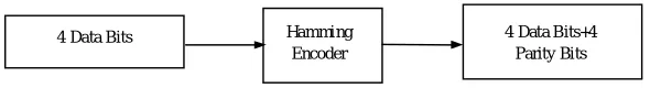
1) Hamming Encoder: The hamming encoder generates the SECDED code which is the extended (8, 4) Hamming code. A
[image:3.612.157.452.602.642.2]parity bit is added to the (7, 4) Hamming code to form the extended Hamming code. The (8,4) code means that the frame to be transmitted is 8 bits wide where 4 denotes the number of parity bits and the remaining 4 bits are data bits. Thus, 4 data bits are fed into the encoder to give 8 bit frame which consists of 4 data bits and 4 parity bits also called hamming bits. The transmitter transmits the encoded 8 bit data frame. The generation of extended (8, 4) hamming code is shown in fig. 1.
Figure 1: Generation of extended (8, 4) Hamming code.
The fig. 2 shows the data format of the extended hamming code where D1 to D4 are the data bits and C1 to C4 are the parity check bits. The extra parity check bit used to calculate the parity of the data frame is denoted by C3 (LSB).
4 Data Bits Hamming
Encoder
Technology (IJRASET)
Figure 2: Data format of extended (8, 4) Hamming code.
The following equations give the parity check bits.
C3 = D1⊕D2⊕D3⊕D4 (1)
C1 = D1⊕D2⊕D4 (2)
C2 = D1⊕D3⊕D4 (3)
C4 = D2⊕D3⊕D4 (4)
2) Hamming Decoder: The received data frame is decoded by using the syndrome. The error position can be found by decoding the syndrome. Once the position is identified the error at that position is corrected by changing the binary bit value. A single bit error can be corrected whereas a double bit error cannot be corrected thus to indicate a double bit error a flag is raised. The decoding algorithm is as follows. A1 = D1⊕D2⊕D3⊕D4⊕C1⊕C2⊕C3⊕C4 (5)
A2 = D2⊕D3⊕D4⊕C4 (6)
A3 = D1⊕D3⊕D4⊕C2 (7)
A4 = D1⊕D2⊕D4⊕C1 (8)
The A1 syndrome gives the parity bit and A2, A3 and A4 gives the error position. No error is present if we obtain the syndrome as ‘0000’ else indicates errors and if its single bit error then it is corrected.
III. COMPARISON
Name of codes Capability FPGA Device Throughput Slices Application
CRC
Burst Error detection
Spartan TM-2 10gbps 294 Ethernet
Reed-Muller
Multiple error detection and correction
Spartan3XC35400 29-10gbps 110
Aerospace, Avionics
Hamming SECDED Spartan3XC35200 41.3gbps 46
satellite communication
Table1: Comparison of error coding algorithms
The comparison between error coding algorithms is shown in table1. In the above comparisons made we get to know that the throughput for Hamming code is the highest. Since throughput increases the efficiency also increases. When efficiency increases performance of the system becomes good.
www.ijraset.com Volume 4 Issue VI, June 2016 IC Value: 13.98 ISSN: 2321-9653
International Journal for Research in Applied Science & Engineering
Technology (IJRASET)
©IJRASET: All Rights are Reserved
828
IV.CONCLUSION
By comparing the algorithms like CRC, Reed-Muller and Hamming we can conclude the efficiency for Hamming code is the best. As the efficiency increases it reduces the power consumed and there by the area and cost. In these codes the FPGA implementation of Hamming code is relatively simple allowing communications systems perform high-speed FEC. It is best suited for least noisy high-speed channels of communications.
REFERENCES
[1] Sindhuja Muppalla, Koteshwara Rao Vaddempudi, A Novel VHDL Implementation of UART with Single Error Correction and Double Error Detection Capability SPACES-Dept of ECE, KL UNIVERSITY, 2015.
[2] Ma Youjie, Zhang Haitao, Zhou Xuesong, Qi Ming, The Realization of the CRC Arithmetic which is based on DSP International Forum on Computer Science-Technology and Applications, May 2009.
[3] K. Tokiwa, T.Sugimura, M. Kasahara, T. Namakawa, New decoding algorithm for Reed - Muller codes, IEEE Transactions on Information Theory, Volume: 28, Issue: 5, Year: 1982
[4] Jun Jin Kong and Keshab K. Parhi, Interleaved Cyclic Redundancy Check (CRC) Code, Dept of ECE, University of Minnesota, 2003
[5] R.W. Hamming, Error detecting and error correcting codes, The Bell System Technical journal Vol. XXIX, American Telephone and Telegraph company, Vol. 2, April 1950.
[6] Paramdeep Singh and Amandeep Kaur, Error detection of 16 Multiple Bits using Reed Muller Algorithm International conference on wireless Network and embedded system, 2011.