©IJRASET: All Rights are Reserved
695
Design and Analysis of Leaf Spring Using
Composite Materials
S. Arun Kumar
Assistant Professor - Department of Mechanical Engineering, Apollo Engineering College, Chennai
Abstract--This project describes design and experimental analysis of composite leaf spring made of glass fiber reinforced polymer. The objective is to compare the load carrying capacity, stiffness and weight savings of composite leaf spring with that of steel leaf spring. The design constraints are stresses and deflections. The dimensions of an existing conventional steel leaf spring of a light commercial vehicle are taken. Same dimensions of conventional leaf spring are used to fabricate a composite multi leaf spring using E- Glass/Epoxy unidirectional laminates. Static analysis of 2D model of conventional leaf spring is also performed using ANSYS 10 and compared with experimental results. Finite element analysis with full load on 3-D model of composite multi leaf spring is done using ANSYS and the analytical results are compared with experimental results.
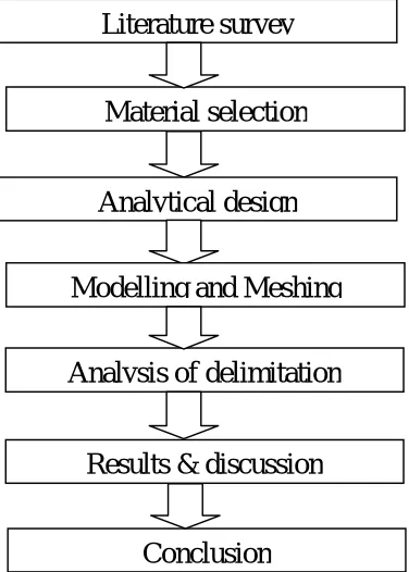
[image:2.612.210.398.290.553.2]I. METHODOLOGY
FIG 1. Flow Diagram for Leaf Spring
A. Composite Material
A composite material is defined as a material composed of two or more constituents combined on a macroscopic scale by mechanical and chemical bonds. Typical composite materials are composed of inclusions suspended in a matrix. The constituents retain their identities in the composite. Normally the components can be physically identified and there is an interface between them. Many composite materials offer a combination of strength and modulus that are either comparable to or better than any traditional metallic materials. Because of their low specific gravities, the strength weight-ratio and modulus weight-ratios of these composite materials are markedly superior to those of metallic materials.
The fatigue strength weight ratios as well as fatigue damage tolerances of many composite laminates excellent. For these reasons, fiber composite have emerged as a major class of structural material and are either used or being considered as substitutions for metal in many components in aerospace, automotive and other industries.
Analysis of delimitation
Material selection
Literature survey
Analytical design
Modelling and Meshing
Results & discussion
©IJRASET: All Rights are Reserved
696
Another unique characteristic of many fiber reinforced composites is their high internal damping. This leads to better vibration energy absorption within the material and results in reduced transmission of noise and vibration to neighboring structures. High damping capacity of composite materials can be beneficial in many automotive applications in which noise, vibration, and hardness is a critical issue for passenger comfort.
Among the other environmental factors that may cause degradation in the mechanical properties of some polymeric matrix composites are elevated temperatures, corrosive fluids, and ultraviolet rays. In many metal matrix composites, oxidation of the matrix well as adverse chemical reaction between fibers and matrix are of great temperature applications. In a FRP leaf spring, the inter laminar shear strengths is controlled by the matrix system used. Since these are reinforcement fibers in the thickness direction, fiber do not influence inter laminar shear strength. Therefore, the matrix system should have good inter laminar shear strength Characteristics compatibility to the selected reinforcement fiber. Many thermo set resins such as polyester, vinyl ester, Fiber reinforcement plastics (FRP) fabrication. Among these resin systems, epoxies show better inter laminar shear strength and good mechanical properties. Hence, epoxies is found to be the best resins that would suit this application. Different grades of epoxy resins and hardener combinations are classifieds, based on the mechanical properties.
B. Applications
Commercial and industrial applications of composites are so varied that it is impossible to list them all. The major structural application areas, which include aircraft, space, automotive, sporting goods, and marine engineering. A potential for weight saving with composites exists in many engineering field. Other structural chassis components, such as drive shafts and road wheels, have been successfully tested in the laboratories and are currently being developed for future cars and vans. The metal matrix composites containing either continuous or discontinuous fiber reinforcements, the latter being in the form of whiskers that are approximately 0.1 to 0.5μm in diameter and have a length to diameter ratio up to 200.
Particulate-reinforced metal matrix composites containing either particles or platelet that ranges in size from 0.5 to 100μm. Dispersion-strengthened metal matrix composites containing particles that are less than 0.1μm in diameter. And metal matrix composites are such as directionally solidified eutectic alloys.
Benefits: Weight reduction High strength Corrosive Resistance Low specific gravity.
C. Stresses Due To Support Hinges
The master leaf of a laminated spring is hinged to the supports. The support forces induce, stresses due to longitudinal forces and stresses arising due to possible twist. Hence, the master leaf is more stressed compared to other the graduated leaves. Methods to reduce additional stresses could be,
Master leaf is made of stronger material than the other leaves.
Master leaf is made thinner than the other leaves. This will reduce the bending stress as evident from stress equation. Another common practice is to increase the radius of curvature of the master leaf than the next leaf.
©IJRASET: All Rights are Reserved
697
The master leaf has a larger radius of curvature compared to the additional leaf that is placed below so obviously a gap will be created between the two leaves as indicated in the figure. Now, an initial bent is created during assembly by tightening the central bolt. Therefore, some amount of compressive stress will be produced at the inside curvature of the master leaf. Similarly, at the outside curvature of the master leaf tensile stress will be produced. Both these stresses are initial stresses in the master leaf. However, by such operation of tightening the central bolt, the additional leaf that is placed beneath the master leaf has a tendency to flatten out and as a result the stress pattern of the additional leaf will be reverse of that of the master leaf, tensile stress is produced at the inner curvature and compressive stress is produced at the outer curvature. Hence, when the spring is loaded, for both the master leaf and the additional leaf, tensile stress will be produced at the inner curvature and compressive stress will be produced at the outer curvature. Therefore, due to opposite nature of initial stress and loading stress, the master leaf will experience lesser stress on both the surfaces. However, due to same nature of initial stress and loading stress, the additional leaf is stressed more compared to the master leaf. But, it is to be noted that the higher stress on the additional leaf is actually shared between all other leaves than the master leaf. This practice of stress relief in the master leaf is known as Nipping of leaf spring. As a matter of fact, all the leaves of a laminated leaf spring do have certain amount of nipping, so that there will be gaps between the leaves, as a result the stresses will be uniformly distributed and accumulated dusts can also be cleaned.
D. Specification of the Problem
[image:4.612.70.543.363.685.2]The objective of the present work is to design, analyses, Glass Fiber/Epoxy complete composite leaf spring without end joints and a conventional steel leaf spring and analyse it to arrive at their results. By comparing these results we will be able to select the better of these two materials. This is an alternative, efficient and economical method over wet filament-winding technique.
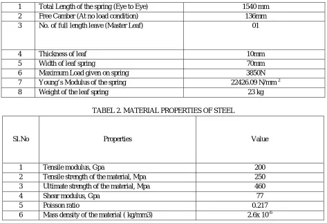
TABLE. 1. SPECIFICATION OF EXISTING LEAF SPRING
1 Total Length of the spring (Eye to Eye) 1540 mm
2 Free Camber (At no load condition) 136mm
3 No. of full length leave (Master Leaf) 01
4 Thickness of leaf 10mm
5 Width of leaf spring 70mm
6 Maximum Load given on spring 3850N
7 Young’s Modulus of the spring 22426.09 N/mm 2
8 Weight of the leaf spring 23 kg
TABEL 2. MATERIAL PROPERTIES OF STEEL
Sl.No Properties Value
1 Tensile modulus, Gpa 200
2 Tensile strength of the material, Mpa 250
3 Ultimate strength of the material, Mpa 460
4 Shear modulus, Gpa 77
5 Poisson ratio 0.217
©IJRASET: All Rights are Reserved
698
Table 3. MATERIAL PROPERTIES OF E-GLASS/EPOXY
Sl. No Properties Value
1 Tensile modulus along X-direction (Ex), MPa 34000
2 Tensile modulus along Y-direction (Ey), MPa 6530
3 Tensile modulus along Z-direction (Ez), MPa 6530
4 Tensile strength of the material, Mpa 900
5 Compressive strength of the material, Mpa 450
6 Shear modulus along XY-direction (Gxy), Mpa 2433
7 Shear modulus along YZ-direction (Gyz), Mpa 1698
8 Shear modulus along ZX-direction (Gzx), Mpa 2433
9 Poisson ratio along XY-direction (Nuxy) 0.217
10 Poisson ratio along YZ-direction (NUyz) 0.366
11 Poisson ratio along ZX-direction (NUzx) 0.217
12 Mass density of the material ( kg/mm3) 2.6x 10⁻⁶
13 Flexural modulus of the material, MPa 40000
14 Flexural strength of the material, MPa 1200
E. Calculation for Leaf Spring
Length of spring (Master leaf) 2L = 380mm
Width = 50mm
Thickness =10mm
n=9, nf=2, ng=7.
Length of leaves
Effective length = 2L – Width of leaf =380 – 50 = 330mm
Ineffective length = width of length =50mm
Smallest leaf length, (l1) =(Effective length/n-1) + Ineffective Length
= (330/9-1) + 50
= 92mm
Second leaf Length (l2) = (Effective length*2 /n-1)+ Ineffective Length
= (330*2/9-1) + 50 = 133mm
Third leaf Length (l3) = (Effective length*3/n-1)+ Ineffective Length
= (330*3/9-1) + 50 = 174mm
Fourth leaf Length (l4) = (Effective length*4 /n-1)+ Ineffective Length
= (330*4/9-1) + 50 = 215mm
Fifth leaf Length (l5) = (Effective length*5/n-1)+ Ineffective Length
= (330*5/9-1) + 50 =257mm
Six leaf Length (l6) = (Effective length*6 /n-1)+ Ineffective Length
= (330*6/9-1) + 50 = 298mm
Seven leaf Length (l7) = (Effective length*7 /n-1)+ Ineffective Length
©IJRASET: All Rights are Reserved
699
Eight leaf Length (l8) = (Effective length*8 /n-1)+ Ineffective Length
= (330*8/9-1) + 50 = 380mm
Nine leaf Length (l9) = (Effective length*9 /n-1)+ Ineffective Length
= (330*9/9-1) + 50 = 478mm
F. Solidworks
Solid Works is a 3D mechanical CAD (computer-aided design) program that runs on Microsoft Windows and is being developed by Dassault Systems Solid Works Corp., a subsidiary of Dassault Systems, S. A. (Vélizy, France). Solid Works is currently used by over 2 million engineers and designers at more than 165,000 companies worldwide. FY2011 revenue for Solid Works was 483 million dollars.
G. Modelling
Solid Works is a Para solid-based solid modeler, and utilizes a parametric feature-based approach to create models and assemblies. Parameters refer to constraints whose values determine the shape or geometry of the model or assembly. Parameters can be either numeric parameters, such as line lengths or circle diameters, or geometric parameters, such as tangent, parallel, concentric, horizontal or vertical, etc. Numeric parameters can be associated with each other through the use of relations, which allows them to capture design intent. Design intent is how the creator of the part wants it to respond to changes and updates. For example, you would want the hole at the top of a beverage can to stay at the top surface, regardless of the height or size of the can. SolidWorks allows the user to specify that the hole is a feature on the top surface, and will then honor their design intent no matter what height they later assign to the can. Features refer to the building blocks of the part. They are the shapes and operations that construct the part. Shape-based features typically begin with a 2D or 3D sketch of shapes such as bosses, holes, slots, etc. This shape is then extruded or cut to add or remove material from the part. Operation-based features are not sketch-based, and include features such as fillets, chamfers, shells, applying draft to the faces of a part, etc.
Building a model in SolidWorks usually starts with a 2D sketch (although 3D sketches are available for power users). The sketch consists of geometry such as points, lines, arcs, conics (except the hyperbola), and splines. Dimensions are added to the sketch to define the size and location of the geometry. Relations are used to define attributes such as tangency, parallelism, perpendicularity, and concentricity. The parametric nature of SolidWorks means that the dimensions and relations drive the geometry, not the other way around. The dimensions in the sketch can be controlled independently, or by relationships to other parameters inside or outside of the sketch.
In an assembly, the analog to sketch relations are mates. Just as sketch relations define conditions such as tangency, parallelism, and concentricity with respect to sketch geometry, assembly mates define equivalent relations with respect to the individual parts or components, allowing the easy construction of assemblies. SolidWorks also includes additional advanced mating features such as gear and cam follower mates, which allow modeled gear assemblies to accurately reproduce the rotational movement of an actual gear train.
Finally, drawings can be created either from parts or assemblies. Views are automatically generated from the solid model, and notes, dimensions and tolerances can then be easily added to the drawing as needed
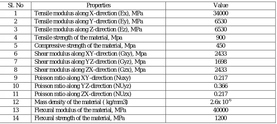
H. Drawings of Leaf Spring
Front View
©IJRASET: All Rights are Reserved
700
[image:7.612.162.424.83.519.2]FIG. 3. ORTHOGRAPHICS VIEWS OF LEAF SPRING
FIG 4. ISOMETRIC VIEW OF LEAF SPRING
II. MODELLING AND ANSYS
A. Design Of 3D Model
Step 1:
©IJRASET: All Rights are Reserved
701
Step 3:
Step 4:
Step 5:
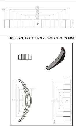
[image:8.612.41.514.34.619.2]Step 6:
FIG 5. STEP BY STEP MODELLING OF LEAF SPRING
B. ANSYS 14.5
ANSYS is an engineering simulation software (computer-aided engineering, or CAE) developer that is headquartered south of Pittsburgh in the South point business park in Cecil Township, Pennsylvania, and United States. ANSYS was listed on the NASDAQ stock exchange in 1996. In late 2011, ANSYS received the highest possible score on its Smart Select Composite Ratings according to Investor's Business Daily. The organization reinvests 15 percent of its revenues each year into research to continually refine the software.
©IJRASET: All Rights are Reserved
702
variety of industries use ANSYS software. The tools put a virtual product through a rigorous testing procedure (such as crashing a car into a brick wall, or running for several years on a tarmac road) before it becomes a physical object.
C. ANSYS Workbench Platform
The ANSYS Workbench platform is the framework upon which the industry’s broadest and deepest suite of advanced engineering simulation technology is built. An innovative project schematic view ties together the entire simulation process, guiding the user through even complex multi physics analyses with drag-and-drop simplicity. With bidirectional CAD connectivity, powerful highly-automated meshing, a project-level update mechanism, pervasive parameter management and integrated optimization tools, the ANSYS Workbench platform delivers unprecedented productivity, enabling Simulation-Driven Product Development.
D. Analysis of Leaf Spring
Step 1: Import the Solidworks 3D model into ANSYS Step 2: Mesh Preview of our design
FIG. 6 MESH PREVIEW OF OUR DESIGN
[image:9.612.103.467.251.341.2]E. Structural Steel
[image:9.612.92.492.256.685.2]FIG.7 .EQUIVALENT STRAIN ANALYSIS OF STEEL
©IJRASET: All Rights are Reserved
703
FIG.9 TOTAL DEFORMATION ANALYSIS OF STEEL
F. EPOXY
FIG.10 EQUIVALENT STRAIN ANALYSIS OF EPOXY
FIG.11 EQUIVALENT STRESS ANALYSIS OF EPOXY
©IJRASET: All Rights are Reserved
704
G. Carbon Fiber
FIG.13 EQUIVALENT STRAIN ANALYSIS OF CARBON FIBER
[image:11.612.119.494.84.692.2]FIG. 14 EQUIVALENT STRESS ANALYSIS OF CARBON FIBER
©IJRASET: All Rights are Reserved
705
III. RESULT AND DISCUSSION
A. Various Values Taken From ANSYS
MATERIALS EQUIVALENT
STRAIN EQUIVALENT STRESS TOTAL DEFORMATION WEIGHT STRUCTURAL STEEL 0.00023027
3.9727e7 1.7783e-5
2.95 kg
EPOXY 0.000083127
3.9489e 7
6.4368e-6 1.8729kg
CARBON FIBER 0.0003825 3.9615e7 6.4368e-6
. 2.026kg STEEL/EPOXY/ CARBON FIBER 0.00022252 4.378e7
1.6208e-5 2.455kg
EPOXY/ CARBON FIBER
[image:12.612.80.528.102.352.2]0.0001668 5.2503e7 1.1373e-5 2.1450kg
TABLE 4. VARIOUS VALUES TAKEN FROM ANSYS
The various properties of various materials are taken from ansys and compare all of these which one is the best. The shaded material namely Epoxy is the best by the following properties like Equivalent Strain, Equivalent Stress, Total Deformation, Weight
IV. CONCLUSION
Since Epoxy is an orthotropic material Stress developed by using this material is little higher than that of steel for same loading conditions. But the strength of the Fiber material (Epoxy) is much higher than the Steel. So Factor of Safety is very high for using this material. At the same time the mass density of Epoxy of is very less compared to Steel. So weight of fiber leaf spring is very less. Strength to weight ratio is very high for this fiber leaf spring.
REFERENCES
[1] Pankaj Saini, Ashish Goel, Dushyant Kumar B. Tech 4th Year Student, Department of ME, Moradabad Institute of Technology, Moradabad, Uttar Pradesh, INDIA 2006.
[2] T.N.V.Ashok Kumar, E.Venkateswara Rao, S.V.Gopal Krishna 1Sir C.R.Reddy College of Engineering, Eluru, Ap, India 2,3Dept. of ME, Sir.C.R. Reddy College of Engineering, Eluru, AP, India. 2011.
[3] Ashvini P.lad , Prof.B.S.gandhare, Prof.A.S.Aradhye, Prof.N.V.Hargude PG student, Sinhgad college of Engineering, Korti, Pandharpur Assistant professor, Sinhgad college of Engineering, Korti, Pandharpur 4Associate professor. PVPIT Budhagaon, SangliVolume 4, Issue 4, April 2015
[4] Rupesh N. Kalwaghe1, Prof. K. R. Sontakke1ME Student, PLIT &MS, Yelgaon (Buldhana), India .HOD of Mechanical Department, PLIT & MS, Yelgaon (Buldhana), 2009.
[5] Parkhe Ravindra, Mhaske Raman, Belkar Sanjay ISSN: 2319–6378, Volume-2, Issue-4, February 2014.