Matrix Converter Technology for Wind Energy
Conversion Systems
L.Pattathurani1, Rajat Kumar Dwibedi2, Dr.S.S.Dash3 1
Assistant Professor, Jeppiaar Institute of Technology, Chennai
2
Assistant Professor, Jeppiaar SRR Engineering College, Chennai
3
Professor, SRM University, Chennai
Abstract: In recent years, wind energy has become one of the most important and promising sources of renewable energy, which demands additional transmission capacity and better means of maintaining system reliability. The evolution of technology related to wind systems industry leaded to the development of a generation of variable speed wind turbines that present many advantages compared to the fixed speed wind turbines. These wind energy conversion systems are connected to the grid through Voltage Source Converters (VSC) to make variable speed operation possible. The studied system here is a variable speed wind generation system based on Doubly Fed Induction Generator (DFIG). The Matrix Converter has several advantages over traditional rectifier-inverter type power frequency converters. It provides sinusoidal input and output waveforms, with minimal higher order harmonics and no sub-harmonics; it has inherent bi-directional energy flow capability; the input power factor can be fully controlled. The proposed converter is capable of direct ac/ac power conversion and, except for a few small-snubber elements; it does not require the use of any input inductors or a dc-link capacitor. Here DFIG introduction and AC-AC converter control and finally the SIMULINK / MATLAB simulation for Matrix Converter as well as for grid connected doubly Fed Induction Generator and corresponding waveforms are discussed.
Keywords: Matrix Converter, Doubly fed Induction Generator, Sinusoidal Pulse Width Modulation.
I. INTRODUCTION
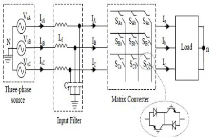
With increased penetration of wind power into electrical grids, DFIG wind turbines are largely deployed due to their variable speed feature and hence influencing system dynamics. DFIGs are widely used for variable speed generation and they are the most important generators for wind energy applications. For DFIG, the power converters are connected to the rotor for restricted speed range typically 30% of the nominal power. In a conventional implementation of a grid-connected DFIG, back-to-back converters are used to connect the DFIG rotor to the utility. The rotor side converter controls the magnetizing and torque of the rotor currents. The grid side converter regulates the voltage in the dc bus of the back- to-back converters. In this paper, back-to-back converters are replaced by a Matrix Converter. The Matrix Converter provides bidirectional power flow, sinusoidal input/output currents, and controllable input power factor. When compared to back-to-back converters, the Matrix Converter has some significant advantages. For instance, due to the absence of electrolytic capacitors, the Matrix Converter can potentially be robust and reliable. The space saved by Matrix Converter, compared to a conventional back to- back converter, has been estimated as a factor of three. Therefore, in some applications, the Matrix Converter can be embedded in the machine itself. Furthermore, there is no intrinsic limitation to the Matrix Converter power.
A sinusoidal pulse width modulation (SPWM) technique is used to control the Matrix Converter, regulating the rotor torque and magnetizing currents. Fig.1 shows the proposed wind energy conversion system (WECS). In the MatrixConverter input side, a
second- order LC power filter is used to improve the current waveform and reduce the input voltage distortion. The interaction
between the MatrixConverter and input power filter may produce resonances and even instability in the system.
II. WIND ENERGY CONVERSION SYSTEM
larger wind turbines in the 3-6 MW range. These all wind turbines are based on Variable wind speed operation with pitch control using a direct driven synchronous generator or a Doubly Fed Induction Generator. The major advantage of the DFIG is that the Power Electronic equipment only has to drive a part of the total system power; this means that the losses in the Power Electronic converters are reduced as well as the cost.
Fig 1: WECS Structure
III. DOUBLY FED INDUCTION GENERATOR
A. Introduction to DFIG
Wind turbines use a doubly-fed induction generator (DFIG) consisting of a wound rotor induction generator and an AC-AC IGBT-based Matrix Converter. The stator winding is connected directly to the 50 Hz grid while the rotor is fed at variable frequency through the AC-AC converter. The DFIG technology allows extracting maximum energy from the wind for low wind speeds by optimizing the turbine speed, while minimizing mechanical stresses on the turbine during gusts of wind. Another advantage of the DFIG technology is the ability for power electronic converters to generate or absorb reactive power, thus eliminating the need for installing capacitor banks as values.
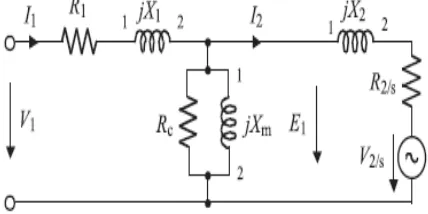
B. Equivalent circuit of DFIG
The induction machine can be represented by the transformer per phase equivalent circuit model where Rr and Xr represent rotor resistance and reactance referred to the stator side. The primary internal stator induced voltage Esi is coupled to the secondary rotor induced voltage Er by an ideal transformer with an effective turns ratio. But the equivalent circuit differs from the transformer equivalent circuit primarily in the effects of varying rotor frequency on the rotor voltage Er. In the case of doubly fed induction machines, however there is a voltage injected in to the rotor windings, so that the normal induction machine equivalent circuit needs to be modified by adding a rotor injected voltage.
[image:3.612.197.411.589.696.2]C. Mathematical model of DFIG
From the equivalent circuit, for a doubly fed induction machine, the real and reactive power of stator PsW, PsQ and rotor PrW, PrQ and the torque developed Tm can be derived as follows.
IV. SINGLE PHASE MATRIX CONVERTER
The Matrix Converter is an array of bidirectional switches as the main power elements, which inter connects directly the power supply to the load, without using any dc-link or large energy storage elements. The most important characteristics of matrix converters are: 1) simple and compact power circuit; 2) generation of load voltage with arbitrary amplitude and frequency; 3) sinusoidal input and output currents; 4) operation with unity power factor; 5) regeneration capability. These highly attractive characteristics are the reason for the tremendous interest in this topology.
Fig 3: Single Phase Matrix Converter Topology
Fig 4: Bi-Directional Switch
The SPMC requires 4 bi-directional switches each capable of conducting current in both directions, blocking forward and reverse direction. The IGBT were used due to its popularity that could lead to high power applications with reasonably fast switching frequency for fine control. The circuit is arranged such that any output lines of the converter can be connected to any input lines.
V. SINUSOIDAL PULSE WIDTH MODULATION
The Sinusoidal Pulse Width Modulation (SPWM) is a well known wave shaping technique in power electronics. For realization, a
high frequency triangular carrier signal Vc is compared with a sinusoidal reference signal Vr of the desired frequency. The
[image:5.612.199.438.176.285.2]crossover points are used to determine the switching instants. The frequency of the output voltage depends on the reference signal frequency. The magnitude ratio of the reference signal (Vr) to that of the triangular signal (Vc) is known as the modulation index (Mi)
Fig 5: Formation of SPWM
[image:5.612.203.445.348.475.2]VI. MAIN MODEL OF SPMC IN MATLAB/SIMULINK
Fig 6: SPMC in MATLAB/SIMULINK
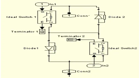
[image:5.612.201.446.544.682.2]VII. BI-DIRECTIONAL SWITCH MODULE
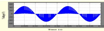
VIII. SIMULATION RESULTS
A. Output voltage Input frequency: 50Hz Output frequency: 100Hz
[image:6.612.240.408.331.381.2]B. Output current Input frequency: 50Hz Output frequency: 100Hz
Fig 8: SPMC with varying output frequency
A. Output voltage Input voltage: 50V Modulation Index: 0.7
B. Output Current Input voltage: 50V Modulation Index: 0.7
Input Frequency: 50Hz Output Frequency: 50Hz
C. Output voltage
IX. THREE PHASE MATRIX CONVERTER
The matrix converter is a single-stage converter, which is composed of an array of m x n bidirectional power switches, each connected between one phase of the input and one phase of the output. Theoretically, the number of input phases m must be at least three and the number of output phases n can be chosen from one to infinity. The basic matrix converter topology which connects a three-phase voltage source to a three-phase load is the most important converter from a practical point of view. A matrix converter is an unlimited frequency changer, which can generate both smaller and bigger output frequency than input frequency of the converter. The output voltage waveforms are constructed by piecing together selected segments of the input voltage waveforms.
Each switch is characterized by a switching function. Each switch SKj , K={ A,B,C}, j={a,b,c} can connect or disconnect phase
K of the input stage to phase j of the load. Output voltages vjN can be synthesized by switching according to a proper
[image:7.612.199.419.278.420.2]combination of these switches. Control of the matrix converter must comply with the following basic two rules. Firstly, any two input terminals should never be connected to the same output line to prevent short-circuit, because the MC is fed by a voltage source. The other an output phase must never be open-circuited owing to the absence of a path for the inductive load current which leads to the over-voltages.
Fig 10: Three Phase Matrix Converter topology
X. SIMULATION RESULTS
a) Input voltages which have 20% third and 10% fifth harmonics
c) Output currents with compensation
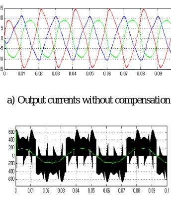
Fig 11: Three-phase output currents for MC the under distorted input voltage conditions (fo = 25 Hz)
[image:8.612.216.397.219.293.2]a) Output currents without compensation
Fig 13: Three-phase output voltage for MC the under distorted input voltage conditions (fo = 25Hz)
a) Output voltage without compensation
[image:8.612.160.407.451.682.2]b) Output voltage with compensation
XI. CONCLUSION
This paper has evaluated the performance of a Matrix Converter based DFIG WECS. Under undesirable effects of the input supply voltage, the proposed compensation technique is an effective method to reduce harmonics of the output current and voltage. The DFIG is able to provide a considerable contribution to grid voltage support during short circuit periods. The matrix converter replaces the use of PWM dc-link converters which reduces losses produced due to the energy storage elements. The MATLAB/ SIMULINK models of Matrix Converter results are validated.
REFERENCES
[1] R. Cárdenas, R. Peña, J. Clare, and P. Wheeler, “Control of the reactive power supplied by a WECS based on an Induction generator fed by a matrix converter,” IEEE Trans. Ind.Electron., vol. 56, no. 2, pp. 429–438, Feb. 2009.
[2] Yulong Li and Nam-Sup Choi, “Carrier Based IEEE APEC Pulse Width Modulation for Matrix Converters,” CD of Conf. Washington DC, February, 2009 [3] Sangshin Kwak, and Hamid A. Toliyat, matrix converters,” “Development of modulation strategy of t wo-phase ac-ac IEEE Trans. Energy Convers., vol.
20, no. 2, pp. 493-494, Jun. 2005.
[4] J. Mahlein, J. Igney, J. Weigold, M. Braun, O. without input Simon, Matrix converter commutation strategies with and voltage sign measurement, IEEE Trans. Ind. Electron., vol. 49, N±2, April 2002, pp. 407-414.
[5] P.W. Wheeler, J. Rodriguez, J.C. Clare, et al.,“Matrix Converters: a Technology Review”, IEEE. Trans. Ind. Electron, Vol. 49, no.2, pp.276-288, April 2007