Image Compression Tool in Wavelets Domain for
Direct Application to Revolutionize, Modeling
and Imaging Technique through Crossbreeding
Wavelet and Cosine Transformation
Nitin Sharma
M.Tech (CS)
Uttarakhand Technical University Dehradun (Uttarakhand)
India
Mayank Singh
, PhD. Department of Computer ScienceKrishana Engineering College Ghaziabad(Uttar Pradesh)
India
ABSTRACT
Compression technique is very critical problem now a day lot of technique are proposing with different method or tool, here compression technique are proposing with the help of cosine transformation and wavelets transformations with „db7‟, „db7‟ and „db8‟. And calculate the compression ratio using crossbreed architecture and wavelets „db7‟, „db7‟ and „db8‟ and in the last try to find out which transformation combination is best with respect to compression ratio. Proposed algorithm is implemented in MATLAB 2010.
General Terms
Wavelet , Compression,
Wavelet Transform, MatlabKeyword
Cosine, wavelets,
,DCT, db6,db7,db81. INTRODUCTION
Image Processing is a technique to enhance raw images received from cameras/sensors placed on satellites, space probes and aircrafts or pictures taken in normal day-to-day life for various applications. Various techniques have been developed in Image Processing during the last four to five decades. Most of the techniques are developed for enhancing images obtained from unmanned spacecrafts, space probes and military reconnaissance flights. Image Processing systems are becoming popular due to easy vailability of powerful personnel computers, large size memory devices, graphics software‟s etc.In image processing, an important part is the compression [3]. This means the reducing the dimensions of the images, to a level that can be easily used or processed. Image compression using transform coding yields extremely good compression, with controllable degradation of image quality.The image compression techniques are broadly classified into two categories depending whether or not an exact replica of the original image could be reconstructed using the compressed image.
These are:
Lossless technique
Lossy technique
1.1 Lossless Compression Technique
In lossless compression techniques, the original image can be perfectly recovered from the compressed (encoded) image [1]. These are also called noiseless since they do not add noise to the signal (image).It is also known as entropy coding since it use statistics/decomposition techniques to eliminate/minimize Redundancy. Lossless compression is used only for a few applications with stringent requirements such as medical imaging.
Following techniques are included in lossless compression:
1. Run length encoding 2. Huffman encoding 3. LZW coding 4. Area coding
1.2 Lossy Compression Technique
Lossy schemes provide much higher compression ratios than lossless schemes. Lossy schemes are widely used since the quality of the reconstructed images is adequate for most applications [10].By this scheme, the decompressed image is not identical to the original image, but reasonably close to it.
In this prediction – transformation – decomposition process is completely reversible .The quantization process results in loss of information. The entropy coding after the quantization step, however, is lossless. The decoding is a reverse process. Firstly, entropy decoding is applied to compressed data to get the quantized data. Secondly, de quantization is applied to it & finally the inverse transformation to get the reconstructed image. Major performance considerations of a lossy compression scheme include[6]:
31
Lossy compression techniques includes following schemes:
1. Transformation coding 2. Vector quantization 3. Fractal coding
4. Block Truncation Coding 5. Subband coding
2.TRANSFORMATION
2.1 Discrete Cosine Transform
The discrete cosine transform (DCT) helps separate the image into parts (or spectral sub-bands) of differing importance [2]. The DCT is similar to the discrete Fourier transform: it transforms a signal or image from the spatial domain to the frequency domain [5].
The basic operation of the DCT is as follows:
The input image is N by M;
f(i,j) is the intensity of the pixel in row i and column j;
F(u,v) is the DCT coefficient in row k1 and column k2 of the DCT matrix.
For most images, much of the signal energy lies at low frequencies; these appear in the upper left corner of the DCT.
Compression is achieved since the lower right values represent higher frequencies, and are often small - small enough to be neglected with little visible distortion.
The DCT input is an 8 by 8 array of integers. This array contains each pixel's gray scale level;
8 bit pixels have levels from 0 to 255.
2.2 Wavelet transform
Wavelet transform exploits both the spatial and frequency correlation of data by dilations (or contractions) and translations of mother wavelet on the input data[8]. It supports the ultiresolution analysis of data i.e. it can be applied to different scales according to the details required, which allows progressive transmission and zooming of the image without the need of extra storage.
The wavelet transform (WT) has gained widespread acceptance in signal processing and image compression [4]. Because of their inherent multi-resolution nature, wavelet-coding schemes are especially suitable for applications where scalability and tolerable degradation are important. Wavelet transform decomposes a signal into a set of basic functions [9]. These basis functions are called wavelets are obtained from a single prototype wavelet y(t) called mother wavelet by dilations and shifting:
Where a is the scaling parameter and b is the shifting parameter
2. Step of Algorithm for proposed method:
Basically consine transformation had applied for image compression with JPEG and individually wavelets transformation can also apply for compression purpose. Here a crossbreeding approach are applying for compression purpose. Algorithms for compression and decomression are discussing here separtly.
Compression:
Step1: Take the input image (e.g 5.bmp).
Step2: using wavelets transformation decomposition at second level (db6.db7,db8)
Fig1: Wavelets Decomposition
Step 3: Find out the block 8x8 after step 2and applied cosine transformation for each block.
Step4: apply quantization and sampling process for each block.
Step5: Save the compressed image into 5_com.NIT
Decompression:
Step 1: read the compressed image (5_com.NIT)
Step2: Apply de sampling and de quantization for
each block.
Step 3: apply inverse cosine transformation.
Step 4: then combined the block and apply inverse
wavelets transformation.
Step 5: Save the decompressed image into
5_dcom.bmp
2.3Compression Tool
In compression tool there are six option first option “take the image” is use for capture the image from the hard disk and second option “Size and dimension of image before compression” is shoe the complete information of input image[7]. When we click on the third button “compression” actually image compression is start after few second MATLAB ask for save the compressed image in .NIT extension. And when we click Decompress the image MATLAB tool ask for which image you want to decompressed, and save the image with different image name. “compare the image”
)
(
1
)
(
,
a
b
t
a
t
b a
button is use for display the information about the decompressed image.
Fig 2: Image Compression Tool
3. RESULT
3.1 Input image Before Compressions
For the proposed algorithms set of input image has been fixed for the different combination (db6, db7,db8) which is shown in below figure (5.bmp, 6.bmp and 8.bmp and 9.bmp). in this section result is shown with different wavelets and calculate the image compression ratio. In below table size is mention before compression and applied the proposed algorithm the hoe much size is reduced.
5.bmp 6.bmp
8.bmp 9.bmp
Fig 3 : Input Image
3.2 Result for Wavelets ‘db6’
[image:3.595.344.513.545.647.2]Here db6 is using with cosine transformation and results shown in below table 1.
Table 1: Compression with ‘db6’
S.No Name
of
image
Dimension Size before
compression
After
compression
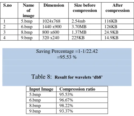
1 5.bmp 1024x768 2.54mb 100KB 2 6.bmp 1440 x900 3.70MB 118KB 3 8.bmp 800 x600 1.37MB 25.1KB 4 9.bmp 320 x240 225KB 13.8KB
3.3 Calculation for Compression ratio with
‘db6’
An image 5.bmp is 2.54 MB before compression and
100Kb after compression what are the values of compression ratio and saving parentage.
Compression ratio= (2.54×1024)/100 =26/1
The interpretation is that 26 pixels of input image are expressed as 1 pixel in the output image.
Saving Percentage =1-1/26 =96.15 %
In the same pattern saving percentage has been calculated for remaining three image (6.bmp, 8.bmp and 9.bmp) and ratio for different sets is shown in table 2. Average compression ratio for „db6‟ for the given input image: 96.27%.
Table2 : Result of compression ratio ‘db6’
Input Image Compression ratio
5.bmp
96.15%
6.bmp
96.88%
8.bmp
98.21%
9.bmp
93.86%
33 Table 3: Decompression with wavelets ‘db6’
S.
n
o
Name of
input
image
Size Size
after
decompr
ession
Dime
nsion
Name of
Decompresse
d image
1 5_COM_DB6. NIT
100K B
2.26MB 1026x7 70
5_DCOM_DB6. BMP
2 6_COM_DB6. NIT
118K B
3.72MB 1442x9 02
6_DCOM_DB6. BMP
3 8_COM_DB6. NIT
25.1 KB
1.38MB 802 x602
8_DCOM_DB6. BMP
4 9_COM_DB6. NIT
13.8 KB
228KB 322 x242
9_DCOM_DB6. BMP
[image:4.595.312.576.320.436.2]Compression with „db7‟ Same process is repeat with wvelt „db7‟ and result is shown in below table 4.
Table 4: Compression with ‘db7’
S.no Name
of
image
Dimension Size before
compression
After
compression
1 5.bmp 1024x768 2.54mb 116KB 2 6.bmp 1440 x900 3.70MB 116KB 3 8.bmp 800 x600 1.37MB 25.5KB 4 9.bmp 320 x240 225KB 15.7kb
Result for wavelets ‘db7’:
An image 5.bmp is 2.54 MB before compression and
116Kb after compression what are the values of compression ratio and saving parentage.
Compression ratio= (2.54×1024)/116 =22.42/1
The interpretation is that 22.42 pixels of input image are expressed as 1 pixel in the output image.
Saving Percentage =1-1/22.42 =95.53 %
Consulate list of compression ratio for wavelye „db7‟ is shown in table 5
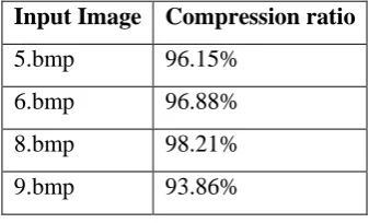
Table5: Result of compression ratio ‘db7’
Input Image Compression ratio
5.bmp 95.53% 6.bmp 96.93% 8.bmp 98.18% 9.bmp 93.02%
Average compression ratio for „db7‟ for the given input image: 95.91%
Table 6: Decompression with ‘db7’
S.no Name of input image
Size Size after de compression
Dimension Name of Decompressed
image 1 5_COM_
DB7.NIT
100KB 2.25MB 1024x768 5_DCOM_ DB7.BMP 2 6_COM_
DB7.NIT
118KB 3.70MB 1440 x900 6_DCOM_ DB7.BMP 3 8_COM_
DB7.NIT
25.1KB 1.37MB 800 x600 8_DCOM_ DB7.BMP 4 9_COM_
DB7.NIT
13.8KB 225KB 320 x240 9_DCOM_ DB7.BMP
Average compression ratio for „db8‟ for the given input image: 95.54%
Table 7
Compression with ‘db8’
Compression ratio for wavelets „db8‟:
An image 5.bmp is 2.54 MB before compression and 116Kb after compression what are the values of compression ratio and saving parentage.
Compression ratio=(2.54×1024)/116 =22.42/1
The interpretation is that 22.42 pixels of input image are expressed as 1 pixel in the output image.
[image:4.595.52.286.355.469.2]Saving Percentage =1-1/22.42 =95.53 %
Table 8:
Result for wavelets ‘db8’Input Image Compression ratio 5.bmp 95.53%
6.bmp 96.67% 8.bmp 98.22% 9.bmp 93.37% S.no Name
of image
Dimension Size before compression
After compression
[image:4.595.310.547.504.708.2]Table 9: Decompression with ‘db8’
S.no Name of input image
Size Size after decom pression
Dimension Name of Decompressed
image
1 5_COM_ DB8.NIT
116KB 2.26MB 1026x770 5_DCOM_ DB8.BMP 2 6_COM_
DB8.NIT
126KB 3.72MB 1442x902 6_DCOM_ DB8.BMP 3 8_COM_
DB8.NIT
24.9KB 1.38MB 802 x602 8_DCOM_ DB8.BMP 4 9_COM_
DB8.NIT
14.9KB 228KB 322 x242 9_DCOM_ DB8.BMP
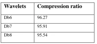
Table 10: Comparison between wavelets and compression ratio
Wavelets Compression ratio
Db6 96.27
Db7 95.91
Db8 95.54
4. CONCLUSION AND FUTURE SCOPE
This algorithm has been successfully programmed using MATLAB and tested. We were able to successfully implement the transformation. Our MATLAB implementation was somewhat simple to write and run. The result shows that the higher data redundancy helps to achieve more compression. Experimental results show good compression ratio for the image is obtained hence we conclude that hybrid algorithm is efficient technique for image compression and decompression to some extent. As the future work on compression of video for storing and transmitting images can be done by other methods of compression because as we have concluded above, the result of the decompressed image is almost same as that of the input image so that indicates that there is no loss of information during transmission. Compression ratio for db6, db7 and db8 is 96.27, 95.91 and 95.54% respectively, now conclude is the db6 wavelets is good for image compression with proposed algorithmsFuture improvements to our algorithm that we considered are Video Compression. Through this we were able to gain valuable hands on experience with the MATLAB programming procedure.
5. REFERENCES
[1] Anna Saro Vijendran, Vidhya.B, “A Hybrid Image Compression Technique Using Wavelet Transformation - MFOCPN and Interpolation “, Global Journal of Computer Science and Technology Volume 11 Issue Version 1.0 March 2011 Online ISSN: 0975-4172
[2] Syed Ali Khayam, "The Discrete Cosine Transform (DCT): Theory and Application" Department of Electrical & Computer Engineering,Michigan State University ,March 10th 2003.
[3] Guy E. Blelloch, "Introduction to Data Compression",ComputerScienceDepartment,Carne gie Mellon University September 25, 2010.
[4] Kamrul Hasan Talukder and Koichi Harada, "Discrete Wavelet Transform for Image Compression and A Model of Parallel Image Compression Scheme for Formal Verification", Proceedings of the World Congress on Engineering 2007 Vol I WCE 2007, July 2 - 4, 2007, London, U.K
[5] Andrew B. Watson, NASA Ames Research, “Image Compression Using the Discrete Cosine Transform”, Mathematica Journal, 4(1),1994, p. 81-88.
[6]
Lotfi, A.A.; Hazrati, M.M.; Sharei, M.; Saeb, A.; “CDF (2, 2) wavelet lossy iamge compression on primitive FPGA (XC9572)”; International Symposium on Signals, Circuits and Systems, ISSCS, 2005. Volume: 2, Page(s): 445 - 448. .[7] Nikolay N. Ponomarenko, Vladimir V. Lukin,
Karen Egiazarian, Jaakko Astola. DCT Based High Quality Image Compression. In Proceedings of SCIA'2005. pp.1177~1185
[8] Karen Lees "Image compression using Wavelets",
Report of M.S. 2002
[9] Saeid Saryazdi and Mehrnaz Demehr(2005),”A blind DCT domain digital watermarking ”,Proceeding of 3rd International Conference:
SETIT ,Tunisia:march-2005
[image:5.595.83.254.250.328.2]