Design of Reversible Programmable Gate Array based
on New Reversible Logic Modules
Saleem M. R. Taha, Ph.D.
Dept. of Electrical Engineering,College of Engineering, University of Baghdad, Jadiryah, Baghdad, Iraq
ABSTRACT
Reversible logic synthesis techniques will definitely be a necessary part of the long-term future of computing. The paper introduces the design of a new reversible logic module (RLM) with three versions I, II, and III. It is universal in two arguments. A proposed design of reversible programmable gate array (RPGA) based on the new (RLM) is presented. It is superior to previous types of (RPGA) structures in that the same type of reversible logic modules is used in the implementation of the entire circuit. Symmetric and no symmetric functions can be realized by the proposed (RPGA). Synthesizing reversibly the logic functions using this method is good for multi-output functions as well as it can be extended to incompletely specified functions.
General Terms
Design, Theory
Keywords
Reversible Logic Module, Reversible Logic Synthesis, RPGA
1.
INTRODUCTION
Interest in reversible logic started when Landauer (1961) proved that traditional binary irreversible gates lead to power dissipation in a circuit regardless of implementation [1]. Each bit of information that is lost, generates KT ln(2) Joules of heat energy, where K is Boltzmann’s constant and T the absolute temperature (Kelvins) at which computation is performed [2, 3]. Bennett (1973) showed that for power not to be dissipated in an arbitrary circuit, it is necessary that this circuit be built from reversible gates. The importance of Bennett’s theorem lies in the technological necessity that every future technology will have to use reversible gates in order to reduce power loss [4]. Reversible logic is an emerging research area. It has attracted significant attention in recent years. It has applications in quantum computing, nanotechnology, low power CMOS, optical computing, and DNA computing. Reversible technologies and the synthesis of reversible networks are potentially very promising areas of study with regard to further technological advances [5]. The high rate of power consumption and the emergence of quantum effects for highly dense ICs are the biggest problems in system design today and in the future. It is necessary to design reliable systems consuming as little power as possible and in which the signals are processed and transmitted at very high speeds with very high signal integrity. In order to reduce power consumption, physical processes have to be logically reversible.
Reversible circuits are those circuits that do not lose information and reversible computation in a system can be performed only when the system comprises of reversible gates. These circuits can generate unique output vector from
each input vector, and vice versa, that is, there is a one-to-one mapping (a permutation) between input and output vectors [6, 7]. Two constraints for reversible logic synthesis are: (1) feedback is not allowed, and (2) fan-out is not allowed (i.e., fan-out = 1). Reversible logic circuits have the same number of inputs and outputs. For an (n, k) function, i.e. function with n-input k-output, it is necessary to add inputs and/or outputs to make it reversible. “Garbage” is the number of outputs added to make an (n, k) function reversible. While the word “constant inputs” is used to denote the preset value inputs that were added to an (n, k) function to make it reversible. One of the important methodologies of reversible logic synthesis is the reversible programmable gate array (RPGA) method. This method is introduced in [8, 9]. It is based on regular structure to realize binary functions in reversible logic. This structure called a 2*2 Net structure, allows for efficient realization of symmetric functions. A regular structure means a logic circuit and its physical layout structure being an array of identical cells regularly connected, or a structure composed of few, regularly connected, structures of this type, called planes. By regularly connected, it is understood that every cell (except of boundary cells) is connected to its k neighbors. There is a subset of Boolean expressions that are specified as sum-of-products, in which every variable is either negated or not negated, but not both [9, 10]. The following three important definitions are mainly based on the topics described in [9].
Definition 1. The variable that stands non-negated (positive) throughout the expression is called a positive polarity variable. Variable that stands always in negated (negative) form is called a negative polarity variable.
Definition 2. Unate function is a function expressed only using AND and OR operators in which every variable has either positive or negative polarity, but not both.
Definition 3. Totally symmetric function that has value 1 when exactly k of its n inputs are equal 1 and exactly (n – k) remaining inputs are equal 0, is called a single-index symmetric function and denoted by Sk(x1, x2, , xn). Analogously, S{i, j, k}denotes the function that is 1 when i, j, or k of its variables are equal 1.
functions. The cells of both planes are implemented using different reversible logic modules (RLMs). The main contribution of this paper is the use of the same RLM in synthesizing the cells of the entire RPGA structure. That will simplify both the circuit’s design and implementation. As
well, the paper presents a new type of RLMs with three versions giving more flexibility in the design process. In addition, the paper gives a solution to the realization problem of no symmetric functions in RPGAs.
First plane Second plane
C MAX(A,B,C) 0 0 MAX(A,B) =(A+B)+C
A = A+B = S1,2,3(A,B,C) S1,2,3
B MIN(A,B) C(A+B) S1,2,3
= A*B S2,3 S2,3(A,B,C) =(A*B)+C(A+B) S2,3 S3 S3 MIN(A,B,C) =(A*B)*C=S3(A,B,C)
S1,2 S2
[image:2.595.54.420.135.320.2]Arbitrary symmetric functions
Fig 1: Realization of 3-input 2-output function < S1, 2(A, B, C), S2(A, B, C) > in RPGA.
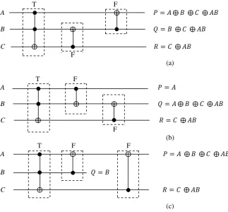
T F
A B
C
F
(a)
T F
A B C
F (b)
T F F
A
B
C
(c)
Fig 2: The three versions of Saleem RLM, (a) Saleem-I, (b) Saleem-II, and (c) Saleem-III.
2.
THE NEW REVERSIBLE LOGIC
MODULE (SALEEM)
Reversible (3, 3) gates, that are universal in two arguments, can be used for the construction of the RPGA. Reversible gates are computationally universal if they can be used to generate AND, OR, NOT gates, i.e. they can be used to generate any Boolean functions. A new (3, 3) reversible logic
module (RLM), called Saleem, is designed in this work to implement the AND/OR cells of the RPGA. It is universal in two arguments. It consists of a Toffoli gate and two Feynman gates connected in three different ways (versions), called Saleem – I, II and III, as shown in Figure 2 (the Toffoli and Feynman gates are denoted as T and F, respectively).
Max/Min
gate
Max/Min
gate
Max/Min
gate
Feyn.
gate
Feyn.
gate
Feyn.
gate
Feyn.
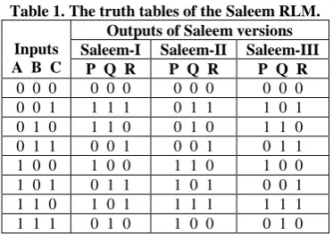
[image:2.595.56.380.358.658.2]The truth tables of the Saleem RLM are shown in Table 1, from which it is clear that the Saleem RLM is balanced but not conservative. The Saleem RLM is universal in two arguments, as is proved in Table 2. The production of cofactors for the (3, 3) Saleem RLM is shown in Table 3.
Table 1. The truth tables of the Saleem RLM.
Inputs A B C
Outputs of Saleem versions Saleem-I Saleem-II Saleem-III
P Q R P Q R P Q R
0 0 0 0 0 0 0 0 0 0 0 0
0 0 1 1 1 1 0 1 1 1 0 1
0 1 0 1 1 0 0 1 0 1 1 0
0 1 1 0 0 1 0 0 1 0 1 1
1 0 0 1 0 0 1 1 0 1 0 0
1 0 1 0 1 1 1 0 1 0 0 1
1 1 0 1 0 1 1 1 1 1 1 1
[image:3.595.315.544.148.283.2]1 1 1 0 1 0 1 0 0 0 1 0
Table 2. Proof of universality of the Saleem RLM in two arguments.
Saleem-I
Inputs Outputs
A = 0 P = B C, Q = B C, R = C A = 1 P = , Q = C, R = B C B = 0 P = A C, Q = C, R = C B = 1 P = , Q = , R = A C C = 0 P = A + B, Q = , R = AB C = 1 P = , Q = , R =
Saleem-II
Inputs Outputs
A = 0 P = 0, Q = B C, R = C A = 1 P = 1, Q = , R = B C B = 0 P = A, Q = A C, R = C B = 1 P = A, Q = , R = A C C = 0 P = A, Q = A + B, R = AB C = 1 P = A, Q = , R =
Saleem-III
Inputs Outputs
A = 0 P = B C, Q = B, R = C A = 1 P = , Q = B, R = B C B = 0 P = A C, Q = 0, R = C B = 1 P = , Q = 1, R = A C C = 0 P = A + B, Q = B, R = AB C = 1 P = , Q = B, R =
3.
PROPOSED DESIGN OF RPGA
BASED ON SALEEM RLM
The Saleem RLM is required to achieve the AND and OR operations when it is used to implement the cells in the first plane of the RPGA, while it is required to achieve the EXOR and copy operations when it is used to implement the cells in the second plane.
From Tables 2 and 3, it is clear that; when the input C = 0, the Saleem-I, II, and III RLMs can achieve the AND and OR operations. Thus, any one of these three RLMs can be used to implement the cells in the first plane. For the second plane, the Saleem-II (with the input B = 0) and the Saleem-III (with the input A = 0) can be used to implement the cells in this plane. For the circuit regularity, the same type of Saleem RLMs is used in both planes of the RPGA. The choice is made to use the Saleem-II RLMs for the implementation of
the cells for the whole RPGA circuit. The notations for the Saleem-II RLMs used in the first and the second planes are shown in Figure 3. The realization of 4-input 3-output function in RPGA using the Saleem-II RLM is shown in Figure 4.
Table 3. Demonstration of the number of cofactors for the (3, 3) Saleem RLM.
Saleem-I Saleem-II Saleem-III (11 cofactors) (11 cofactors) (11 cofactors)
P(0, B, C) = B C P(1, B, C) = P(A, 0, C) = A C
P(A, B, 0) = A + B P(A, B, 1) =
Q(1, B, C) = C Q(A, 1, C) =
Q(A, B, 0) = Q(A, B, 1) = R(A, B, 0) = A B R(A, B, 1) =
P(0, B, C) = 0 P(1, B, C) = 1 P(A, 0, C) = A Q(0, B, C) = B C
Q(1, B, C) = Q(A, 0, C) =A C Q(A, B, 0) = A + B Q(A, B, 1) =
R(0, B, C) = C R(A, B, 0) = A B R(A, B, 1) =
P(0, B, C) = B C P(1, B, C) = P(A, 0, C) = A C
P(A, B, 0) = A + B P(A, B, 1) =
Q(0, B, C) = B Q(A, 0, C) = 0 Q(A, 1, C) = 1 R(0, B, C) = C R(A, B, 0) = A B R(A, B, 1) =
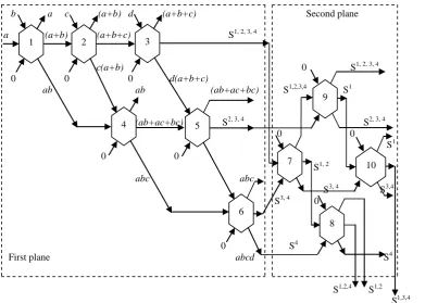
It is clear from Figure 4, that horizontal outputs from the first plane PUS functions are EXOR-ed in the second plane to create arbitrary symmetric functions at the bottom. The additional garbage outputs of the Saleem-II RLMs (hexagon cells) in the first plane must be forwarded to the primary outputs of the first plane, and can be used in the same way as the horizontal outputs to realize some nonsymmetrical functions in the second plane with no repeated variables. This facility does not exist in the previous RPGA structures (shown in Figure 1). The following example should clarify this fact.
Example The RPGA method is to be used to realize the no symmetric function:
.
The Karnough map (K-map) of the function f can be obtained by EXOR-ing the two K-maps of functions S1, 2, 3, 4 and (ab + ac + bc), as shown in Figure 5. Referring to Figure 4, the function f can be realized by EXOR-ing the first PUS function horizontal output of the first plane with the additional garbage output of cell 5.
4.
DISCUSSION
The proposed design uses the same type of RLMs in implementing both the first and second planes of the RPGA. The cost of the Saleem RLM used in implementing the second plane is more than the cost of the Feynman reversible gates that are usually used. But, the advantage is the simplicity in fabricating the entire RPGA circuit with the same type of cells. That is not the case in the first plane, where the Saleem RLM is used to implement (MAX/MIN) cells.
In the previous RPGA structure, the circuit shown in Figure 6 is used as the (MAX/MIN) cell [11]. It consists of one Feynman gate and two Toffoli gates. The cost of Saleem RLM is less than that of the circuit in Figure 6. To explain that, let us consider the following definition [11]:
Definition 4. The cost of a reversible circuit equals the summation of the cost values of its individual gates.
It should be noted that the cost for a single gate depends on the type but also on the technology. The following metrics are used:
[image:3.595.81.259.226.603.2] Quantum cost denotes the effect needed to transform a reversible circuit to a quantum circuit. For example, the quantum cost of Feynman gate is 1 and that of the Toffoli gate is 5.
Transistor cost denotes the effort needed to realize a reversible circuit in CMOS. The transistor cost of a reversible gate is (8 s) where s is the number of control lines.
B = Input 2 P = A = Garbage B = Control = 0 P = Output 1 = A
A = Input 1 Q = Output 1 A = Input 1 Q = Output 2 = A + B = A C
[image:4.595.61.465.71.218.2]C = Control = 0 R = Output 2 = A * B C = Input 2 R = Output 3 = C (a) (b)
Fig 3: The notations for the Saleem-II RLMs (hexagon cells), (a) used in the first RPGA plane, (b) used in the second RPGA plane.
b a c (a+b) d (a+b+c) Second plane
a (a+b) (a+b+c) S1, 2, 3, 4
c(a+b) 0 S1, 2, 3, 4 0 0 0 d(a+b+c) ab ab (ab+ac+bc) S1,2,3,4 S1
(ab+ac+bc) S2, 3, 4 S2, 3, 4 0 0
S1 0 0
S1, 2 abc abc S3, 4 S3,4 S3, 4 0
0 S4
First plane abcd S4
S1,2,4 S1,2 S1,3,4
Fig 4: Realization of 4-input 3-output function < S1, 2(a, b, c, d), S1, 2, 4(a, b, c, d), S1, 3,4(a, b, c, d) > in RPGA.
cd cd cd ab 00 01 11 10 ab 00 01 11 10 ab 00 01 11 10 00 1 1 1 00 1 1 1 00 01 1 1 01 1 1 1 1 01 1 1
11 = 11 1 1 1 1 11 1 1 1 1 10 1 1 10 1 1 1 1 10 1 1
f S1, 2, 3, 4 (ab + ac + bc) Fig 5: Realization of the function f by EXOR-ing of two functions.
1 Garbage output
A (A AND B)
B (A OR B)
Fig 6: The OR/AND (MAX/MIN) reversible circuit used in previous methods.
Saleem-II
II
Saleem-II
II
1 2 3
4 5
6
9
7
8
[image:4.595.53.457.263.542.2]The gate count is often used to evaluate the quality of a reversible circuit. Also, the quantum cost metric is popular because it represents a measure for the quantum computation and considers larger gates to be more costly. The transistor cost model is a relatively new model that arose with the application of reversible circuits to the area of low-power CMOS design. Gate count and quantum cost are primarily considered as it allows a fair comparison of synthesis results with respect to previous work. Transistor costs are additionally addressed where appropriate.
[image:5.595.74.405.271.426.2]Consider the circuit in Figure 6, it has a gate count of 3, quantum cost of 11, and transistor cost of 40, while the Saleem RLM circuit has a gate count of 3, quantum cost of 7, and transistor cost of 32, respectively. Therefore, the use of Saleem RLM circuit is superior to the use of the circuit in Figure 6.
The proposed work can be used to synthesize nonsymmetrical Boolean functions, by firstly converting them to symmetric
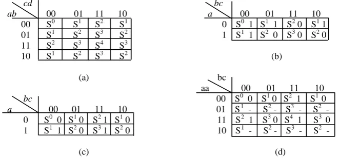
functions. Then they can be easily synthesized by the proposed technique. One method to characterize a symmetry that might exist in a logic function is using symmetry indices Si [12]. A symmetry index (Si) has superscript i equals to the count of the number of “1” values in the states of variables in the corresponding cell in a K-map as in Figure 7a. The K-map in Figure 7b represents a three variable symmetric function, because the values of a specific symmetry index are equal for the whole map (S0 is equal to 1, S1 is equal to 1, S2 is equal to 0, and S3 is equal to 0). A function which is not symmetric can be made symmetric by repeating its variables. This method of variable repetition transforms the values of K-map cells which make the function nonsymmetrical into don’t care, i.e. cases that never occur, which make the function symmetric. The K-map in Figure 7c represents a nonsymmetrical function that has conflicting values in the same symmetry indices, which are S1 and S2. The function can be made symmetric by repeating variable a as in Figure 7d.
cd bc
ab 00 01 11 10 a 00 01 11 10 00 S0 S1 S2 S1 0 S0 1 S1 1 S2 0 S1 1 01 S1 S2 S3 S2 1 S1 1 S2 0 S3 0 S2 0 11 S2 S3 S4 S3
10 S1 S2 S3 S2 (b)
(a) bc
aa 00 01 11 10 bc 00 S0 0 S1 0 S2 1 S1 0
a 00 01 11 10 01 S1 - S2 - S3 - S2 - 0 S0 0 S1 0 S2 1 S1 0 11 S2 1 S3 0 S4 1 S3 0 1 S1 1 S2 0 S3 1 S2 0 10 S1 - S2 - S3 - S2 - (c) (d)
Fig 7: (a) K-map of a 4 variable function showing the symmetry indices, (b) K-map of a 3 variable symmetric function, (c) no symmetric function with conflicting values, (d) function in (c) being made symmetric by repeating variable a.
bc bbc
a 00 01 11 10 a 000 010 110 100 101 111 011 001 0 S0 0 S1 1 S2 1 S1 0 0 S0 0 S1 - S2 0 S1 - S2 - S3 1 S2 - S1 1 1 S1 1 S2 0 S3 0 S2 1 1 S1 1 S2 - S3 1 S2 - S3 - S4 0 S3 - S2 0
(a) (b)
Fig 8: (a) K-map of a no symmetric function with conflicting values of symmetry indices, (b) function in (a) being made symmetric by repeating variable b.
The no symmetrical function in Figure 7c cannot be represented by elementary symmetric functions S0, S1, , Sn. However, after it is converted to symmetric form as shown in Figure 7d, it can be represented as f = S2, 4(a, b, c) and easily realized by the proposed RPGA structure. Here, the repetition of the input variable a is required to achieve this process. The choice of repeated variables depends on the type of non-symmetry of the function, and the size of the RPGA depends on it. For example, the function in Figure 8a is not symmetric because of conflicting values in the same symmetry indices of S1 and S2. Here, the repetition of variable a will not convert the function to a symmetric form. But the repetition of variable b will do, as shown in Figure 8b. The function can be represented as f = S1, 3(a, b, c) and be easily realized by the proposed RPGA. Note that the cases corresponding to the values of bbc = 010, 100, 101, or 011 in K-map of Figure 8b
are impossible to be occurred and are denoted as dashes (-), or don’t cares, in their respective cells.
5.
CONCLUSIONS
[image:5.595.72.419.487.551.2]efficient in realizing nonsymmetrical functions by converting them first to symmetrical forms, via repeating variables, and then applying the design procedure. A promising task for the future is to make a scheme (rules and guidelines) for the choice of the variables to be repeated such that the final design is minimal. Also, the cases of incompletely specified functions can be considered as further work. Finally, the use of the new Saleem RLM makes the design of the proposed RPGA more flexible as compared with previous methods. As well, it becomes possible for some types of nonsymmetrical functions to be realized directly without the need for variable repetitions due to the use of the new RLM, a facility not found in previous methods.
6.
REFERENCES
[1] Landauer, R. 1961. Irreversibility and heat generation in the computing process. IBM J. of Research and Development, vol.5, no. 3, 183-191.
[2] Dueck, G. W. and Maslov, D. 2003. Reversible function synthesis with minimum garbage outputs. Proceedings of the 6th International Symposium on Representations and Methodology of Future Computing Technologies (RM), Trier, Germany, March 2003, pp. 154-161.
[3] Maslov, D. and Dueck, G. W. 2003. Garbage in reversible designs of multiple output functions. Proceedings of the 6th International Symposium on Representations and Methodology of Future Computing Technologies (RM), Trier, Germany, March 2003, pp. 162-170.
[4] Bennet, C. H. 1973. Logical reversibility of computation. IBM J. of Research and Development, 17 (November 1973), 525-532.
[5] Maslov, D., Dueck, G. W., and Miller, D. M. 2005 Synthesis of Fredkin-Toffoli reversible networks. IEEE Transactions on Very Large Scale Integration (VLSI) Systems, vol.13, no. 6, (June 2005), 765-769.
[6] Lukac, M., Pivtoraiko, M., Mishchenko, A., and Perkowski, M. 2002. Automated synthesis of generalized
reversible cascades using genetic algorithms.
Proceedings of 5th International Workshop on Boolean Problems, Freiburg, Germany, 19-20 September 2002, pp. 33-45.
[7] Thapliyal, H., Kotival, S., and Srinivas, M. B. 2006. Novel BCD adders and their reversible logic implementation for IEEE 754r format. Proceedings of the IEEE 19th International Conference on VLSI Design (VLSID’06), Hyderabad, India, 4-7 January 2006, pp. 387-392.
[8] Al-Rabadi, A. N. 2004. Reversible logic synthesis: from fundamentals to quantum computing. Springer-Verlag.
[9] Perkowski, M., Kerntopf, P., Buller, A., Chrzanowska-Jeske, M., Mishchenko, A., Song, X., Al-Rabadi, A., Jozwiak, L., Coppola, A., and Massery, B. 2001. Regularity and symmetry as a base for efficient realization of reversible logic circuits. Proceedings of IWLS’01, Lake Tahoe, California, USA, 12-15 June 2001, pp. 90-95.
[10] Perkowski, M., Kerntopf, P., Buller, A., Chrzanowska-Jeske, M., Mishchenko, A., Song, X., Al-Rabadi, A., Jozwiak, L., Coppola, A., and Massery, B. 2001. Regular realization of symmetric functions using reversible logic. Proceedings of EUROMICRO Symposium on Digital Systems Design (Euro-Micro’01), Warsaw, Poland, September 2001, pp. 245-252.
[11] Wille, R., and Drechsler, R. 2010. Towards a design flow for reversible logic. Springer Science + Business Media B. V.