International Journal of Emerging Technology and Advanced Engineering
Website: www.ijetae.com (ISSN 2250-2459,ISO 9001:2008 Certified Journal, Volume 3, Issue 9, September 2013)
155
Manufacturing of Fiber Glass & Development, Static Load
Testing, Analysis of Composite Leaf Spring
Karthik. Badugu
1,
Sathaiah.Gajam
2, B. Mahasenadhipathi Rao
31PG Student, 3Asst. Professor, Department of Mechanical Engineering, Sreenidhi Institute of Science & Technology: Hyderabad A.P. INDIA
2General Manager (process& technology) Goa glass Fiber Ltd, (Braj Binani Group) Survey No.220, Village- Colvale, Bardez
GOA-403513
Abstract - This paper describes manufacturing of fiber glass& development and static load testing& analysis of composite leaf spring made of glass fiber reinforced polymer E glass/epoxy mono composite leaf spring using hand layup method. Leaf springs are one of the oldest suspension components that are being still used widely in automobiles. The automobile industry has shown increased interest in the use of composite leaf spring in the place of conventional steel leaf spring due to high strength to weight ratio. The leaf spring was modeled in pro/E and the analysis was done using ANSYS software when the composite leaf spring is developed with same dimensions as of steel leaf spring it is observed that the deflections in composite leaf spring are greater than steel leaf spring. Deflections for the same load and the stresses in the composite leaf spring are less when compared with steel leaf spring. The spring weight is also observed to be 70-80% lower than steel leaf spring.
Keywords - Composite Material, Steel Leaf Spring, Pro-E, ANSYS.
I. INTRODUCTION
Composite Materials: Composite materials are engineered materials made from two or more constituent materials with significantly different physical or chemical properties which remain separate and distinct on a macroscopic level within the finished structure.
MANUFACTURING OF FIBER GLASS
Stage 1
Consists of glass manufacture i.e. the fusion of selected, weighed and mixed raw materials such as sand, limestone etc in glass making furnace. This stage ends with liquid glass flowing directly into the fiber forming furnaces called “Bushings”.
Stage 2
Consists of fiber forming. Continuous glass fibers are made by the rapid mechanical attenuation of molten drops of glass exuding from tip located on the underside of the bushing.
Molten glass from each tip during fiber drawing forms a meniscus as a result of attenuation. These filaments pass through a light spray and then over an applicator which transfers a protecting and lubricating size onto the filaments from which they are gathered into a suitably shaped shoe. From there the strand passes to the winder. A winder consists of a slightly expandable rotating cylinder called cullet. The thickness of the fiber being wound on the cullet is allowed to reach the required thickness before the cullet is stopped and the bundle is removed; the winding operation is then recommenced.
Stage 3
The cake, having been coated by a fiber size, is wet and requires drying before further processing. After drying and conditioning the fiber cakes are ready to be converted into saleable products.
II. COMPOSITE LEAF SPRING
International Journal of Emerging Technology and Advanced Engineering
Website: www.ijetae.com (ISSN 2250-2459,ISO 9001:2008 Certified Journal, Volume 3, Issue 9, September 2013)
156
According to the studies made a material with maximum strength and minimum modulus of elasticity in the longitudinal direction is the most suitable material for a leaf spring. Fortunately, composites have these characteristics. The suspension leaf spring is one of the potential items for weight reduction as it accounts for 10 to 20% unsprung weight. This helps in achieving the vehicle with improved riding qualities. It is well known that springs are designed to absorb and store energy and then release it. Hence, the strain energy of the material becomes major factor in designing the springs. The relationship of the specific strain energy can be expressed as
Where: σ is the strength,
ρ is the density and
E is the young’s modulus of the spring material.
The introduction of composite materials was made it possible to reduce the weight of the leaf spring without any reduction on the load carrying capacity and stiffness. Since, the composite materials have more elastic strain energy, storage capacity and high strength to weight ratio as compared to those of steel problem definition
The aim of the paper is to design a leaf spring and develop a mono composite leaf using Eglass/Epoxy (Unidirectional mat) with Hand lay-up technique. A static test rig is fabricated in order to conduct deformation test under various loading conditions on both steel and Composite leaf spring. The static result of Mono composite leaf spring is compared with steel leaf spring. A three dimensional model of entire leaf spring (one master and six graduated leaves) is modeled using Solid works. Finite element technique (ANSYS) is carried out to predict the behavior of both steel and Composite leaf springs. The study is extended to determine the effect of orientation of composite material on the leaf spring for deformation and stresses. The FEA results compared with Experimental results for both Steel and Composite Leaf spring.
III. DESIGN OF STEEL LEAF SPRING
Design Criteria: In the present work a leaf spring for 2Ton carrying capacity truck is designed. The dimensions and the number of leaves of the Composite leaf spring is taken as that of the conventional steel leaf spring.
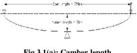
Fig 3.1(a): Camber length
Specifications of leaf spring:
Design parameters of the existing six –leaf steel spring used in this work includes:
Span length or overall length (eye to eye), 2L = 790mm Full bump load=1.5 times of (truckload/4) = 3250N Camber Height = 70mm
Dimensions of each leaf: thickness, t = 6mm; width, b = 60mm
Design stress without accounting for sudden impact loads, f = 625N/mm2
Ineffective length (distance between the two bolts) = 90mm (assumption)
So, effective length = 2L-90 = 790-90 = 700mm Therefore, l = 350mm
Calculation of Number of leaves:
From the formula,
l= half of the effective length = 350mm, z = number of leaves
Zg = number of graduated leaves = 4
Zf = number of full length leaves = 2
= = 50.63mm
Length of each leaf:
Small leaf = + Ineffective length (I.L)
= + 90 = 230mm
Next leaf = 2 + I.L = 370mm
[image:2.612.376.514.149.203.2]International Journal of Emerging Technology and Advanced Engineering
Website: www.ijetae.com (ISSN 2250-2459,ISO 9001:2008 Certified Journal, Volume 3, Issue 9, September 2013)
157
Next leaf = 4 + I.L = 650mm
Next leaf = 5 + I.L = 790mm
Master leaf = span length + allowance for the eyes
= 2L + (d+t).2
= 790 + (25+6).2 = 984.7≈985mm
d= inside diameter of eye end = 25
t = thickness
Therefore number of leaves, z= 5.83≈6leaves
So for the above conditions, the number leaves that are required is 6.
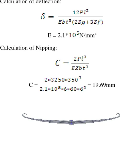
Calculation of deflection:
E = 2.1* N/mm2 Calculation of Nipping:
C = = 19.69mm
Figure 3.1(b): A 3D model of leaf spring
1. Design Of Composite Leaf Spring
The dimensions of the composite leaf spring are taken as that of conventional leaf spring. The design parameters selected are as follows:
Each composite leaf consists of 13 layers.
Width of each Layer is 60mm.
Total thickness of leaf with 22 layers is 6mm Width of the leaf is 60mm.
2.LAY-UP SELECTION
The amount of elastic energy that can be stored by a leaf spring varies directly with the square of the maximum allowable stress and inversely with the modulus of the elasticity both in longitudinal direction. Composite materials like E-glass/ Epoxy in the direction of fibers have good characteristics for storing strain energy. So, the lay-up is selected to be unidirectional along the longitudinal direction of the spring. Fabrication and testing of Leaf spring.
3.Fabrication Of Composite Leaf Spring:
Fabrication of composite leaf spring is done by a sequence of steps. The steps that are involved during the fabrication are:
4.MANDREL:
A steel plate is taken and bent it to the curvature of the steel leaf spring (Semi –Elliptical curvature) and cut to the dimensions of the steel leaf spring. This is used as mandrel to fabricate composite leaf spring by using hand lay-up process.
5.TEMPLATE:
A thick cardboard is taken and cut to exact dimensions to that of the steel leaf spring with respect to length and width. This template is used to cut fiber mat to the exact dimensions required. 22 pieces of the exact dimensions required are cut from the fiber mat using the template.
6. HAND LAY-UP TECHNIQUE:
[image:3.612.48.248.397.632.2]International Journal of Emerging Technology and Advanced Engineering
Website: www.ijetae.com (ISSN 2250-2459,ISO 9001:2008 Certified Journal, Volume 3, Issue 9, September 2013)
158
7. LAY-UP SEQUENCE:
All the uni-directional fiber layers which are cut using the template are arranged one over the other till 13 layers.
8. APPLICATION RELEASING AGENTS:
Releasing agent is necessary before doing the fabrication process as it helps the component to get released out of the mandrel easily without damaging the mandrel or the component fabricated. In the fabrication of composite leaf spring, plaster of paris is applied on the steel mandrel to protect the mandrel from damage. Wax polish is applied on the Plaster of Paris to get a smooth finish and for easy removal of the composite leaf spring.
9. PROCEDURE OF MIXING RATIOS AND FABRICATION:
In the fabrication process of composite leaf spring Epoxy resin is used. For 1Kg of epoxy resin 100gms of hardener is mixed. This mixture is firstly applied on the wax polish and then a layer is placed on the mandrel and the resin is applied again. This process is continued till 13 layers. This process took about 30 minutes. After the lay-up is finished the setup is kept undisturbed for 24hrs at room temperature. Care is taken during the individual lay-up of the layers to eliminate the fiber distortion which would result in lowering in strength and rigidity of the spring as a whole.
IV. SETTING AND REMOVAL OF SPRING
Approximately 30minutes is required for resin setting and the composite leaf spring is removed from the mandrel without damaging the component. The composite leaf spring removed from the mandrel has the same dimensions as that of the steel leaf spring
V. TRIMMING AND FINISHING
Sharp edges produced during the fabrication process are removed by trimming them using a Grinding cutting tool. Surface finish is produced on the component using grinding machine.
VI. TESTING OF COMPOSITE AND STEEL LEAF SPRING
The steel and composite leaf springs are tested by using the UTM at Jyothi spectro analysis. The experimental setup is shown in the fig 4.3. The leaf springs to be tested are examined for any defects like cracks, surface abnormalities, etc. The springs are loaded from 0 to maximum deflection by applying loads with regular intervals and all the readings are noted down.
VII. RESULTS & CONCLUSIONS
Three Dimensional Finite Analysis:
Structural analysis was performed using the finite element method using ANSYS software. Modeling was done for steel leaf spring using 8 node 3D brick element (solid 45) and composite leaf spring shell 99 element. Also deflections for different loads are also observed for both composite and steel leaf springs
Loading and Boundary Conditions:
The spring is symmetrical so only one half of the span length is considered for analysis to save the calculation time.One end of the spring is constrained as Uy=0 ,Uz=0 and Rotz=0.The load is applied on the free end of the leaf spring in steps of 2Kg.The deformations and stresses under various loading conditions are computed.
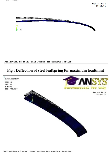
[image:4.612.330.553.375.687.2]ANSYS Results:
Fig : Deflection of steel leafspring for maximum load(mm)
International Journal of Emerging Technology and Advanced Engineering
Website: www.ijetae.com (ISSN 2250-2459,ISO 9001:2008 Certified Journal, Volume 3, Issue 9, September 2013)
[image:5.612.58.281.124.667.2]159
[image:5.612.331.552.129.295.2]Fig: Deflection of Composite leaf spring for maximum load(mm)
Fig: Loading and boundary condition of steel leaf spring
[image:5.612.63.279.130.302.2]Fig :Loading and boundary conditions of composite leaf spring
Fig : Stress of composite leafspring(0 deg) for max load
VIII. COMPARISON OF EXPERIMENTAL AND FEA RESULTS
Table1
Comparison of Experimental results with ANSYS for Deflection in steel Leaf spring
S. No Load (N) Deflection (mm) (experiment)
Deflection (mm) (ANSYS)
1 105 5.31 5.92
2 181.2 6.79 7.27
3 257.2 7.98 10.3
4 333.2 8.98 12.4
5 426.5 11.9 14.5
6 485.3 15.63 17.3
7 599.2 17.08 22.1
8 789.2 23.02 26.1
9 1140 34.68 37.8
10 1320 36.78 40.5
11 1650 43.7 51.2
12 2000.3 47.3 49.5
13 2400.5 54.36 56.4
14 2890 61.4 66.5
15 3150 68.5 75.2
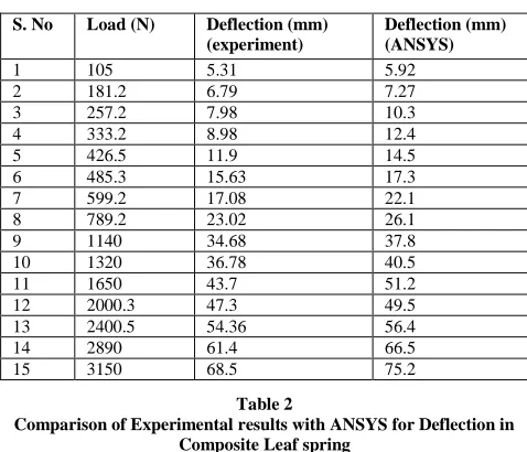
Table 2
Comparison of Experimental results with ANSYS for Deflection in Composite Leaf spring
S. No Load (N)
Deflection (mm) (experiment)
Deflection (mm) (ANSYS)
1 105 10.18 10.37
2 181.2 15.43 18.91
3 257.2 17.54 21.72
4 333.2 22.94 27.9
5 409.2 29.14 33.5
6 485.3 33.47 35.4
7 599.2 36.82 38.3
8 789.2 37.25 39.7
9 1140 47.12 49.4
10 1520 53.54 59.5
11 1900 63.75 65.1
[image:5.612.324.563.363.568.2] [image:5.612.332.553.508.714.2]International Journal of Emerging Technology and Advanced Engineering
Website: www.ijetae.com (ISSN 2250-2459,ISO 9001:2008 Certified Journal, Volume 3, Issue 9, September 2013)
[image:6.612.324.564.130.529.2]160
Table 3
Stresses Observed in Steel and Composite Leaf Spring Using ANSYS
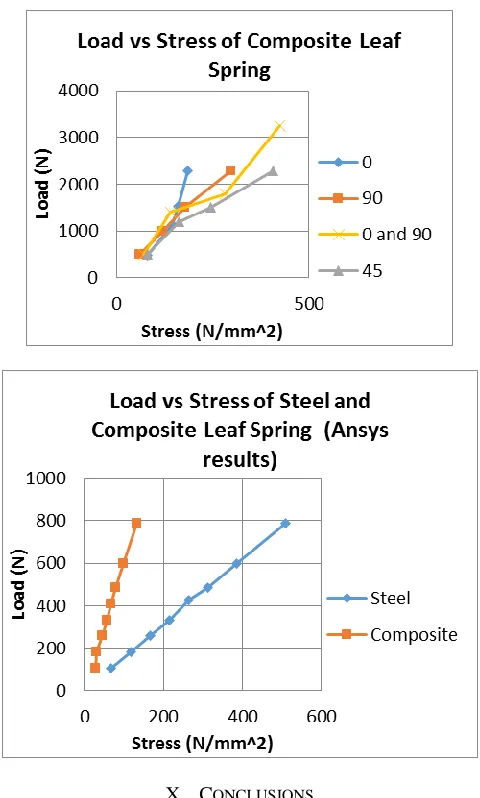
IX. GRAPHS
X. CONCLUSIONS
Composite leaf spring is fabricated using hand lay-up technique. E-glass/ epoxy unidirectional mat is used as the material.
Static Load tests are carried out experimentally to determine deformations.
Behavior of the composite and steel leaf springs for deformations and stresses are predicted using ANSYS software.
Effect of fiber orientation of composite material is also studied for deformations and stresses and is compared with each other.
Comparison between experimental and ANSYS results is also done.
S. No Load (N)
Stresses in steel leaf spring (N/mm2)
Stresses in composite leaf spring (N/mm2)
1 105
67.66 28.66
2 181.2
116.76 31.65
3 257.2
165.73 44.93
4 333.2
214.7 58.216
5 426.5
263.6 66.393
6 485.3
312.36 79.67
7 599.2
386.11 99.59
8 789.2
International Journal of Emerging Technology and Advanced Engineering
Website: www.ijetae.com (ISSN 2250-2459,ISO 9001:2008 Certified Journal, Volume 3, Issue 9, September 2013)
161
Composites having high strain energy so it is good to use it as a springs compared to steel leaf springs.
It is observed that the weight of composite leaf spring is 70% less than that of the steel leaf spring.
Stresses are observed to be low and deformations are high in composite leaf spring when compared with steel leaf spring.
Composites are non-corrosive in nature, light weight, high strain energy capacity, so it is good to use it as a leaf spring because it reduces the weight of the vehicle and fuel consumption.
XI. SCOPE FOR FUTURE WORK
The present study can be extended by reducing more weight and also deflections by designing and fabricating a variable width and thickness leaf spring.
Also study can be done to replace a complete set of steel leaf spring with a composite leaf spring for a vehicle and perform Static load and Dynamic tests.
REFERENCES
[1] Manual on design and application of leaf springs, Spring Design Manual, AE-11, Society of Automotive Engineer Hs 788,1990. [2] Tsai SW, Hahn HT. Introduction to composite materials. Technomic
Publishing; 1980.
[3] ANSYS 5.4, ANSYS Inc., 1997.
[4] Ryan WE. Method of making a molded fiber reinforced plastic leaf spring, US patent 4,560,525 (24/12/1985).
[5] M.M. Shokrieh, D. Rezaei / Composite Structures 60 (2003) 317– 325
[6] R.S. Khurmi, J.K. Kupta. A text book of Machine Design, 2000.
[7] R. M. Jones, Mechanics of Composite Materials. 2e, McGraw-Hill Book Company, 1990.
[8] R.S. Khurmi, J.K. Kupta. A text book of Machine Design, 2000, Chapter. 23, Page. No (866-874).
[9] Kumar Krishnan,AggarwalM.L , “A finite element approach for analysis of a multi leaf spring using CAE tools Research”. Journal of Recent sciences 2012 , Page No.92-96