International Journal of Emerging Technology and Advanced Engineering
Website: www.ijetae.com (ISSN 2250-2459,ISO 9001:2008 Certified Journal, Volume 5, Issue 8, August 2015)
408
Fuzzy Control Development to Quadrotor System
Erick T. Yamamoto
1, Alexandre S. Caporali
2, Paulo R. Barbosa
31,2,3Instituto Federal de Educação, Ciência e Tecnologia de São Paulo, 01109-010 São Paulo, Brazil
Abstract— The objective of this work is to describe the implementation of a model of quadrotor with fuzzy controller. Wherein the quadrotor can be described as an Unmanned Aerial Vehicle (UAV) having four rotors, which causes the machine has greater stability than normal. It has six degrees freedoms, three of them due to the position: height, horizontal movement, vertical movement, and the other three on the course: pitch, roll and yaw. It has four inputs: height, scrolling, pitch and yaw desired; outputs are the power of each rotor necessary to achieve the desired situation from the current state. For this study will be used a hardware architecture and LabVIEW software and tools are specially developed and implemented for an experimental prototype used to test and validate the proposed control approach.
Keywords— UAV, quadrotor, mathematical model, fuzzy control, LabVIEW.
I. INTRODUCTION
Autonomous helicopters are one of the most widely used robotic platforms because they have the ability to vertically take off and land as well as stationary flights.
They are very useful in natural disasters, rescues, structure inspection and geographical mapping. On many occasions the actions involve risks and requires a high mobility and depending on where a small aircraft. Reinforcing the idea of not manned vehicle.
This work presents the model and the simulation of an intelligent control of a quadrotor. The main advantage of the four - planar rotor with respect to a conventional helicopter is the vehicle stability. As mentioned disadvantage is the difficulty of reconciling the four rotors at once.
II. RELATED WORK
The history of unmanned aerial vehicles in the world is old. As old as the history of aviation itself. The idea of a "flying machine" originated and was designed about 2500 years ago in 425 B.C., when Archytas, Greek scientist, created the first UAV (Unmanned Aerial Vehicles-Manned) of all time by building a mechanical bird, a pigeon that could fly moving their wings and get energy from a mechanism in your stomach.
It is alleged that he flew about 200 meters before falling to the ground, since all power was used [1].
In modern times, drones appeared during World War I (1917). For over ten years after the end of World War I, the development of Aerial Vehicles Unmanned suffered a small stagnation, and most ongoing projects aimed at applications in military training tasks. In the mid-40, the height of the Second World War began the increasing use of Unmanned Aerial Vehicles for war purposes in the world. In the decades that followed, advances in technology allowed the use of UAVs in more strategic missions such as reconnaissance and espionage tasks [2].
In the 70s, came the era of modern UAVs, designed to be smaller, cheaper and more efficient. The Vietnam War and the Cold War spurred a variety of UAV development programs [3]. From that time until then, several other projects of aircraft were developed around the world in both the military and civilian sector. A more complete history of the UAVs can be found in [1].
Most applications of UAVs was born within military bodies had strong research and development for recognition, monitoring and offensive actions against enemy positions. Currently, however, other applications of most interest to the civil sector have been R & D target, enabling the industrial and commercial use of those vehicles [2].
III. BACKGROUND
Before developing a model that explains the quadrotor, it is necessary to understand its operation. For it shall be considered a simplified quadrotor, in which disregard the particular effects of the engines, propellers and electronic circuitry required to control it.
International Journal of Emerging Technology and Advanced Engineering
Website: www.ijetae.com (ISSN 2250-2459,ISO 9001:2008 Certified Journal, Volume 5, Issue 8, August 2015)
[image:2.612.72.271.142.269.2]409
[image:2.612.84.266.301.455.2]Figure 1. Simplified Model of Quadrotor.
Figure 2. Angular Movements [4].
By using, the associations described above movements, which are shown in Figure 2, together with the yaw movement, may move in either direction quadrotor the three-dimensional space. Thus, we conclude that control of inclination, or attitude, system and vital for the motion control system as a whole.
To facilitate the nomenclature throughout the work takes up a variable for each basic movement being the same expressed in Table 1.
TABLE I
MOVEMENT SETS RELATED TO FORCE AND TORQUES
Main
Movements Force/Torques
Height U1 [N]
Roll U2 [N.m]
Pitch U3 [N.m]
Yaw U4 [N.m]
A. Dynamic model of the quadrotor
The literature review showed several ways of performing the mathematical modeling of the quadrotor. In this study, we used the model described in [5], based on the Newton- Euler model for a generic body six degrees of freedom.
The equations of motion are defined in the system B, for the following reasons:
• The inertia matrix and time-invariant;
• The symmetric body can be used to simplify the equations;
• Control forces exerted by the engines are given in this system;
• The acceleration measured by the accelerometer is also given in this system.
In this case, equation (1) describes the system movement:
(1)
In this equation, describes the linear speed (in its components u, v and w) describes and ω the angular velocity of the body (in its components p, q and r) given in the coordinate system B. The momentum of a body of six degrees of freedom leads about body mass and its inertia matrix. This dynamic is described in equation (2).
(2)
In equation (2), m and body mass, I3x3 and the dimension of the identity matrix 3 , 03x3 and a square matrix of size 3 with zeros in all positions, I and inertia matrix, FB is the vector of forces acting on the system and τB and the vector of torques acting on the system , both given in B.
Writing (2) equation in matrix form, we obtain the equation (3).
(3)
Where MB and generalized array of inertia of the body, the matrix CB that takes into account the centripetal acceleration and Coriolis vector Λ and the general body forces.
International Journal of Emerging Technology and Advanced Engineering
Website: www.ijetae.com (ISSN 2250-2459,ISO 9001:2008 Certified Journal, Volume 5, Issue 8, August 2015)
410
(4)
(5)
(6)
Equation (3) and completely generic and applies to any body complying with the conditions previously established. However, for the system in question, we can divide the vector Λ into three components according to the nature of the forces acting on the quadrotor.
The first contribution is due to the gravitational vector, given from the acceleration due to gravity g [m / s2] and established in the equation (7). Obviously, this vector only affects linear components, and as a force rather than a torque.
(7)
The second contribution comes from the gyro effects produced by the rotation of the blades. As two are rotating clockwise and the other two in the counterclockwise direction, an imbalance exists when the algebraic sum of the speeds of the rotors is not equal to zero. In addition, if the roll and pitch angles are different from zero, the quadrotor suffers gyro torque according to equation (8). In this equation, Ω and the sum of the speeds of the rotors, given by equation (9), where Ωx is the speed of each motor.
=
(8)
(9)
The last contribution is due to the forces and torques produced directly by the rotors. This is achieved by aerodynamic considerations these are directly proportional to the square of the speed of rotation of the rotors. Equation (10) describes these contributions.
(10)
In equation (10), b is the thrust coefficient, d is the drag coefficient and l is the distance between the rotors and the system’s center of mass.
Thus, it is possible to describe the system dynamics from the following matrix equation (11):
(11) Isolating the derivative of the velocity vector, we get to equation (12).
(12) The equation representing (13) and (12) equation as a system of equations
(13)
The speed of the propellers is given from the equation (14):
(14)
B. Block Diagram of a Quadrotor
International Journal of Emerging Technology and Advanced Engineering
Website: www.ijetae.com (ISSN 2250-2459,ISO 9001:2008 Certified Journal, Volume 5, Issue 8, August 2015)
411
[image:4.612.371.516.158.405.2]From it, and calculating the current position obtained by reading sensors used, a control system "high-level" navigation determines what should be the next position quadrotor. From this, a control system "low - level" position determines what should be the voltage values applied to each mode of motor to achieve the desired position. As quadrotor is, a dynamic system when new readings will vary sensors and the control system should update once more voltage values applied to the motors, thereby characterizing the feedback system.
Figure 3. Block Diagram of Quadrotor.
IV. RESULTS A. Virtual Model in LabVIEWTM
The purpose of the model development is to implement the equations obtained, and act upon the model in order to keep it steady using a fuzzy controller to control the rotation of the engine to clear the error to the entries for height, roll and yaw pitch.
Table 2 shows the values of constants that have been adopted for the simulator, according to calculations and practical tests demonstrated in [5].
TABLE II CONSTANTS ADOPTED
Constant Symbol Value Acceleration of
Gravity g 9,81 m/s
2
Total Mass m 1 kg
Moment of
Inertia on Axis X Ixx
0,04 N*m*s2
Moment of
Inertia on Axis Y Iyy
0,04 N*m*s2
Moment of
Inertia on Axis Z Izz
0,08 N*m*s2
Thrust
coefficient b
56*10-6 N*s2/rad2
Drag coefficient d 1,1*10
-6 N*m*s2/rad2
Distance between center of mass and motor center
L 0,0225 m
Inertia of moment of total turnover
Jtp 7,33*10 -5 N*m*s2
Using the above parameters in the model developed in LabVIEWTM, shown in Figure 4.
[image:4.612.93.248.262.443.2] [image:4.612.333.583.446.631.2]International Journal of Emerging Technology and Advanced Engineering
Website: www.ijetae.com (ISSN 2250-2459,ISO 9001:2008 Certified Journal, Volume 5, Issue 8, August 2015)
412
[image:5.612.324.577.132.222.2]Answers in this mathematical model we get only acceleration, so we build a new VI (virtual instrument) which, in Figure 5, convert values in positions and velocities.
Figure 5. Value Conversion Code.
B. Control Fuzzy
The type of controller used was a fuzzy PD applied to each variable to be controlled, thus totaling four controllers that are implemented by normalizing the proportional and derivative inputs such that the controller receives values between -1 and 1, to ensure this condition, was used blocks and gain saturation, so that the limits of saturation multiplied by no more than up to one module.
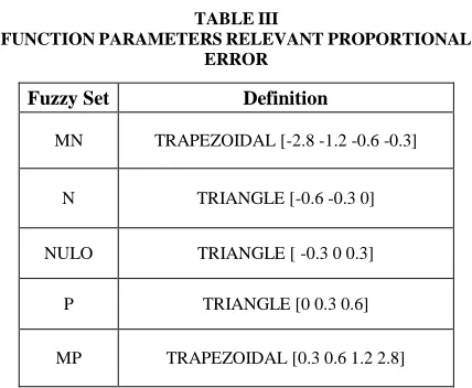
The three membership functions, error, derived from the error and performance level are equal and have the graphical representation, where MN is a very negative value, N a negative value, NULO a value close to zero, P a positive value and MP a very positive value.
The textual representation of the membership function is shown in Table 4 and Figure 6[6].
TABLE III
FUNCTION PARAMETERS RELEVANT PROPORTIONAL ERROR
Fuzzy Set Definition
MN TRAPEZOIDAL [-2.8 -1.2 -0.6 -0.3]
N TRIANGLE [-0.6 -0.3 0]
NULO TRIANGLE [ -0.3 0 0.3]
P TRIANGLE [0 0.3 0.6]
[image:5.612.59.279.184.322.2]MP TRAPEZOIDAL [0.3 0.6 1.2 2.8]
Figure 6. Basic Rules of the Fuzzy Controller.
After created rules we need to convert these values to PWM for rotor operating.
Calculation that describes the relationship of the engines with the basic movements:
PWM1 = HOVER + Z – PITCH – YAW
PWM2 = HOVER + Z – ROLL + YAW
PWM3 = HOVER + Z + PITCH – YAW
PWM4 = HOVER + Z + ROLL + YAW
The force U1 determines the hovering constant value, so that it is equal to the weight force, i.e. no acceleration and stable [7]. In equations (15) and (16) the speed of the motors is determined where the quadrotor keep stable in space, considering m = 1 kg g equal to 9,81m / s² and b , the thrust constant, determined by propeller 56 * 10-6 as previously adopted in Table 2.
(15)
rad/s (16)
It is then necessary to calculate the value in PWM (% ), when applied, cause the engine to reach hovering velocity , so it is considered the battery voltage to 11 volts and the gain of the motor as 1100 rpm / V. Parameters are directly proportional to angular velocity , then we can determine the PWM (%) by equation (17) .
[image:5.612.61.275.517.693.2]International Journal of Emerging Technology and Advanced Engineering
Website: www.ijetae.com (ISSN 2250-2459,ISO 9001:2008 Certified Journal, Volume 5, Issue 8, August 2015)
413
V. CONCLUSION
Analyzing the results obtained it is clear that the application of fuzzy PD control method was successful and managed to stabilize the virtual model implemented by controlling the height and angle. It was noticed that the roll and pitch angles respond faster to control because of the constant inertia are of lesser magnitude, being named the roll axis X of rotation and the y-axis named pitch. The yaw angle is the rotation in the z axis has moment of inertia that most of the other axes, then becoming clear why their response is slower. The noises have greater magnitude for the roll and pitch angles, due to its higher sensitivity, because it has less inertia.
One solution would be to apply filters for the parameters measured by the sensors, decreasing the noise generated by the same, another determining factor in system stability improvement as a whole is increased driver update rate, or increase the frequency of order insurers zero, the controller.
REFERENCES
[1] Bowman, M., Debray, S. K., and Peterson, L. L. 1993. Reasoning about naming systems.
[2] Valavanis, P. K., 2007. Advances in Unmanned Aerial Vehicles: State of teh Art and the Road to Autonomy.
[3] Neto, A. A., 2008. Geração de Trajetórias para Veículos Aéreos Autônomos Não-Tripulados, Master Thesis, Universidade Federal de Minas Gerais, Mina Gerais, Brazil.
[4] Camacho, L., and Yuhas, C. 2004. Civil UAV Capability Assessment. NASA Aeronautics Research Mission Directorate
[Online]. Available:
https://www.nasa.gov/centers/dryden/pdf/111761main_UAV_Capab ilities_Assessment.pdf
[5] Domingues, J.M.B. 2009. Quadcopter prototype, Master Thesis, Universidade Técnica de Lisboa, Lisboa, Portugal.
[6] De Sousa, J. D. A., 2011. Development of unmanned aerial four-rotor, Master Thesis, Faculdade de Engenharia da Universidade do Porto, Porto, Portugal.
[7] Sivanandam S.N., Sumathi S., and Deepa S. N., 2007. Introduction to fuzzy logic using MATLAB.
![Figure 2. Angular Movements [4].](https://thumb-us.123doks.com/thumbv2/123dok_us/8697872.878772/2.612.84.266.301.455/figure-angular-movements.webp)