International Journal of Emerging Technology and Advanced Engineering
Website: www.ijetae.com (ISSN 2250-2459,ISO 9001:2008 Certified Journal, Volume 4, Issue 2, February 2014)
713
A Loop-Free Method on Ethernet Using Undirected
Connectivity Graph
Huu-Hung Phan
1, Tuyet-Thi Anh Mai
2, Tae-Wan Kim
3, Chul-Soo Kim
4 1,2,3,4Computer and Communication Laboratory, Inje University, Gimhae, South KoreaAbstract—IEEE Spanning Tree Protocol (STP) is a layer-2 protocol which provides a loop-free connectivity across various network nodes. It reduces the network topology to a spanning tree where redundant ports are blocked and kept in standby operation mode until a network failure occurs. However, STP does not have any traffic mechanism for load balancing, so that there are several shortcomings such as: heavy congestion especially close to the root, low utilization in links and switches, and severe penalty on the performance and scalability of Metro Ethernet Networks. In this paper, we propose a new approach to model the Ethernet network topology as an undirected connectivity graph using the Bridge Protocol Data Units (BPDUs) frame information exchange in order to build the shortest paths between any switch to remaining switches. By using our proposal, this model can achieve faster recovery time for network failure, improve the load balancing and the average traffic load on links and switches, as well as reduce the bandwidth blocking probability. Analytical methods for full mesh and partial mesh topologies show that using the our proposed model can give about 25% reduction in variance of link utilization, variance of switch utilization, and average number of hop counts compared to STP.
Keywords— Spanning Tree Protocol, Shortest Path Bridging, Spanning Tree Replacement, Metro Ethernet Networks, Loop-free connectivity
I. INTRODUCTION
Ethernet has been developed in many ways over the past 30 years, and widely accepted in enterprise deployments. Nowadays, it has become the main enterprise Local Area Network (LAN) technology with more than 90% data traffic termination on Ethernet ports [1]. Ethernet relies on Media Access Control (MAC) address learning through MAC frames flooding mechanisms [2], so it achieves some advantages: simplicity, plug-and-play, and cheap price. In the past, Ethernet had been initially utilized in small local area network environment (LAN), but nowadays, it is increasingly being deployed in metropolitan and wide area network environments (MAN and WAN) [3]. However, there are a number of problems encountered in these networks such as endless MAC frames, broadcast storms, low utilization, lack of load-balancing, and long recovery time.
Preventing the endless MAC frames, or loop-free connectivity has always been important in Ethernet.
Current researches to reduce these type of network problems are mainly divided in two categories: Spanning Tree Protocol and Link State Protocol. For STP-based approaches, some main researches such as STP [2], Rapid Spanning Tree Protocol (RSTP) [4], and Multiple Spanning Tree Protocol (MSTP) [5] were proposed as the solution to these issues. These protocols provide a simple mechanism to prevent infinite loop frames problem. However, these approaches are unable to overcome the low link utilization, the traffic congestion at root node, load-balancing problem, and take a long time to recover network topology. Other significant approaches also aim to enhance the spanning tree protocol such as Global Open Ethernet (GOE) [6], Alternative Multiple Spanning Tree Protocol (AMSTP) [7], Viking [8], Smartbridge [9], Transparent Spanning-Tree Bridge Protocol with Alternative Routing (STAR) [10] but they do not completely resolve these problems.
In another point of view, some Link state protocol approaches were developed to forward MAC frames along the shortest path. Currently, IEEE 802.1aq Shortest Path Bridging (SPB) [11] and IETF Transparent Interconnection of Lots of Links (TRILL) [12] represent link state protocol adaptions. However, these approaches are complex and require the large changes of the existing Ethernet infrastructure.
International Journal of Emerging Technology and Advanced Engineering
Website: www.ijetae.com (ISSN 2250-2459,ISO 9001:2008 Certified Journal, Volume 4, Issue 2, February 2014)
714
The rest of the paper is organized as follows. Section II presents the related works with the brief overviews about Spanning Tree Protocol based approaches and Link State protocol based approaches. Section III shows the detailed design of our proposed model. An analytical discussion comparing between our proposed mode and Spanning Tree Protocol for two well-known topologies is derived in section IV. The last section draws conclusions, summarizes the proposed results and future works.
II. RELATED WORK
The root cause of infinite loop frames and many following consequences is the MAC frame learning and flooding mechanism in Ethernet. There are two main methods for solving the problem: Spanning Tree Protocol and Link State Protocol.
A. Spanning Tree Protocol
Traditionally, Ethernet-based networks use the STP, standardized in 1998 as IEEE 802.1d [2]. Primarily, STP is used to avoid the infinite loop frames in the networks. STP replies on two different type of BPDUs: Configuration and Topology Change Notification (TCN) BPDUs and five port states: blocking, listening, learning, forwarding, and disabled. Whenever there is a change in the topology, switches rebuild the spanning tree, which can take from 30 to 60 seconds. At any one time, there is only one Spanning Tree in the network.
Although STP has been widely used in Ethernet networks, it has several shortcomings in the context of MAN. First, low link and switch utilization must be considered because the spanning trees restrict the number of ports being used. Hence, in high-capacity Ethernet networks, this restriction translates to a very low utilization of the network. Second, there is only one spanning tree with a root node, so it causes the heavily congestion as links around the root nodes.
An improvement of STP is the Rapid Spanning Tree Protocol (RSTP) [4] specified in IEEE 802.1w. RSTP and STP are quite similar in operation with some main characteristics: BPDU simplification with a single type BPDU frame instead of two different type of BPDUs in STP; RSTP reduces the number of ports states from five in STP to three: discarding, learning and forwarding; and RSTP reduces the convergence time to between 1 and 3 seconds. But, there is also only one Spanning Tree over the entire network. Therefore, RSTP still blocks redundant links to ensure the loop free paths so that the problems of low utilization, vulnerable to failures, and no load balancing are still exist in Ethernet networks.
To resolve using only one Spanning Tree over Ethernet network, MSTP [5] is defined in IEEE 802.1s. MSTP uses a common spanning tree that connects all regions in the network topology. Each region in MSTP has a single internal spanning tree which is an instance of RSTP with its own regional root and several multiple spanning tree instances. The regional roots are in turn connected to the common root that belongs to the common spanning tree. The obvious advantage of MSTP is to have multiple paths to the same destination(s). It means not only better bandwidth efficiency but also the opportunity implemented load-balancing. However, MSTP runs pure RSTP as the underlying protocol, so that it inherits the drawbacks of RSTP. Additionally, MSTP is not easy to configure and has to be used properly configure all the elements in fact manual configuration. Hence, touching the traffic flows from a single region leaving in other regions of MSTP is difficult.
International Journal of Emerging Technology and Advanced Engineering
Website: www.ijetae.com (ISSN 2250-2459,ISO 9001:2008 Certified Journal, Volume 4, Issue 2, February 2014)
715
B. Link-state protocol
The fundamental reason for providing Link-State protocol, or Shortest Path Bridging (SPB), is to leverage physical network infrastructures and improve performance with minimal configurations. Typically at the network layer, the link state protocol routes packets based on the concept of greedy algorithm. Before the link state protocol can begin, it requires the global knowledge of the topology and all the link costs.
Both IETF and IEEE are actively working to deliver Shortest Path based Carrier Ethernet Bridging Solutions. The IETF introduces a new bridging system that reuses most network routing protocols to benefit the Ethernet link layer. It named ―Transparent Interconnection of Lots of Links‖ or TRILL [12]. TRILL proposed RBridges [13], which are enhanced to perform both Layer 2 and Layer 3 forwarding. So that, it needs to modify current Ethernet infrastructure so much and has to define whole new OA&M protocols. On the other hand, the IEEE defined the draft of IEEE 802.1aq ―Shortest Path Bridging‖ [11] to introduce the concept of multiple shortest path tree instances rooted as edge bridges. Like RSTP and MSTP, SPB implements the concept of active topology as a loop-free connectivity with one Shortest Path Tree (SPT) at each active topology. All these approaches have been faced with two major issues. The first issue is the identification of the active topology to answer how to infer the source bridge from the frame header. The second issue is related to congruence requirements between forward and reverse paths on one hand, and between unicast and multicast data paths, on the other hand.
III. METHODOLOGY
C. Proposed Model Design
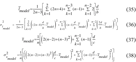
Again we reiterate that the main goal in this paper is to build a switches network topology based on establishment and determination the shortest path to forward MAC frames between switches over network. The shortest path problem is resolved without relying on Spanning Tree Protocol.
To realize this goal, our paper proposes an idea using an undirected graph with each node in the network has the role of a root node in Spanning Tree Protocol’s approaches. Our approach aims to determine an undirected, connectivity sub-graph that has all nodes in network and some links connected any pair of nodes in the initial graph.
Based on this idea, the expected result of our approach is that MAC address table of each switch node in our topology contain all MAC addresses of all switches in network with their ingress ports. Beside of it, guarantee the backward compatibility with current Ethernet infrastructure is necessary. As such, our idea inherits some current Ethernet features with a small change of implementation in our method. We focus on: BPDU frame structure with its four fields (namely BridgeID, PortID, Root Node ID, and Path Cost to Root), BPDU frame exchange mechanism, Ethernet broadcasting and multicasting mechanism.
As mentioned above, we model the initial network topology with each link between pair of switches using its costs as an undirected graph G = (V, E) in two dimensional plane, where V = {v1, v2, …, vn} is the set of switches in network (in here, we call a switch as a node) and E is the set of bidirectional links. Bidirectional links here mean each link between node vi and node vj (vi, vj) ∈ E shows that both vi and vj are covered by each other. In our approach, each bidirectional link is assigned with a cost which is defined in IEEE Link Cost of STP and RSTP. Thus, we express the cost between pair of vertices vi and vj by w(i, j). Link cost represents the different of transfer frame speed between two switches. Another way is used to express the needed cost to transmit a frame along this link and use path cost to show the sum of all link costs of a path. Therefore, we define shortest path as the path with minimal path cost among the paths connecting two vertices. Our algorithm computes the path of w(i, j) which usually relates only to vi and vj, at most to their neighbors. Hence, it makes each vertex of the algorithm possible to collect information locally. However, because of the broadcast mechanism of our topology, the algorithm can collect information over network, and therefore, it guarantees all paths between arbitrary pair of vertices in topology are the shortest paths.
International Journal of Emerging Technology and Advanced Engineering
Website: www.ijetae.com (ISSN 2250-2459,ISO 9001:2008 Certified Journal, Volume 4, Issue 2, February 2014)
[image:4.612.69.280.107.254.2]716
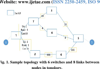
Fig. 1. Sample topology with 6 switches and 8 links between nodes in topology.
In next section, we provide details about the first step in our proposed model. To illustrate, we use a sample topology with 6 switches as Fig. 1.
D. Path cost calculation
In SPT-based approaches, they elected a root node for entire topology, and all path costs of all nodes in network are calculated from the root node. In our approach, as mentioned above, each node vi is itself root node, so all path costs to the nodes in our topology are calculated based on root node vi.
To calculate path cost from root node vi to arbitrary node vj, PaCo(i,j), we base on the set of link costs between vi and vj, LiCo(m,n) where m and n are nodes that belong the path from vi to vj. So that, the path cost from vi to vj is calculated as:
( , ) , ( , )
PaCo i jm nLiCo m n (1)
With our topology in Fig. 1, we can see three path from node 1 to node 5. Used PaCo, three path costs can be calculated as follow. Path1 includes node v1, v7, v3, and v5 with path cost 100 + 10 + 10 = 120. Path2 includes node
v1, v7, v4, and v5 with path cost 100 + 4 + 4 = 108. Path3
with node v1, v2, v6, and v5 has path cost 10 + 100 + 100 = 210.
E. Path cost information exchange mechanism
In this step, each node vi exchanges its current information by generating and multicasting a specific MAC frame. We inherit the BPDU frame mechanism from STP-based approaches, and focus on three fields: Root Node ID, Path Cost, Source MAC address. In the initial phase, each node vi has its role as root node, and Root Node ID of BPDU frame is BridgeID of vi. There are two processes in each node: receiving BPDU frame and multicasting the frame to neighbor nodes. Based on BPDU frame exchange of STP-base approaches, the paper proposes an algorithm to support the path cost information exchange mechanism.
The algorithm describes two processes are happened in a node vi when it received a BPDU frame. Node vi reads information in BPDU frame: Root Node ID vk, Path cost, Port ID, type of BPDU frame, Source MAC address. Node vi checks some information of root node vi in switch to determine if these current information are correspondence with current BPDU frame (Root Node ID, PortID, Source MAC address). Beside of this, vi also checks the current path cost from root node vk in switch if it is more longer than path cost in received BPDU frame. If path cost of BPDU frame is less than one, node vi changes to network topology construction step. At the same time, node vi generates a new BPDU frame with Root Node ID is vk, Path cost is increased with cost of link that current BPDU frame come to vi, Source MAC address is MAC address of vi. New BPDU frame will be multicast to all neighbor nodes of vi.
F. Network topology construction
This step happens at the same time with path cost exchange step. In this step, each node vi tries to build its MAC address table based on the information of BPDU frames which it is containing. In here, each node vi implements Dijkstra’s algorithm selecting between paths from arbitrary root nodes vk to assure the entries which are written in MAC address table of vi are belong in the shortest paths from those root nodes vk to it. This also guarantees each link cost in the link’s set of the paths from a root node to any node in network is smallest.
In the case if there were many equal cost paths from a root node vk to node vi, the node vi compares the source Bridge ID between the arrived BPDU frame of root node vk and the BPDU frame of root node vk contained in vi. Node vi chooses the BPDU frame which has smaller Bridge ID to add or update an entry in MAC address table of node vi. This work guarantees the appropriate selected shortest path and the simplicity of our proposed model.
After this step, each node in our network has already established an undirected, connectivity, and shortest path graph, or we can call shortest path tree, for itself. It means each node has a completed MAC address table that can forward MAC frame to any node in network based on the ingress port and MAC address of node in MAC address table. For convenience, our paper brings a follow definition about each shortest path tree of a root node. So that, each
node vi has its local neighbor node setNeSlican be represented by:
i i
International Journal of Emerging Technology and Advanced Engineering
Website: www.ijetae.com (ISSN 2250-2459,ISO 9001:2008 Certified Journal, Volume 4, Issue 2, February 2014)
717
In the normal case, the stability of network is assured, but if network topology has a change, for example, a failure node or a failure link between two nodes, the network status will be changed to the status of the network topology repairing.
IV. ANALYTICAL DISCUSSION
In this section, we derive an analytical discussion of our proposed model and Spanning Tree Protocol for two well-known mesh topologies: full mesh and partial mesh. The
mesh topologies are used usually for many
telecommunication backbones, as well as the Metro Ethernet network.
G. Evaluation Metrics
To evaluation the algorithms, several different metrics will be defined in this subsection. These metrics are: Relative efficiency, average and variance of link utilization, average and variance of switch utilization, average number of hops, and bandwidth blocking probability.
Relative Efficiency: First of all, as mentioned above, the network is considered as an undirected graph G(V,E). In general, the routing cost of the graph G is defined as:
( , ) ,
C d u v
G u v
(3)
Where d(u,v) is the distance between nodes u and v on G. It is defined as the sum of the cost of the links in the unique path between node pairs. For a graph G with link utilization ω, we have:
( , ) ( ) ( ) ,
CG d u v l e e
u v e E
(4)
Usually, ω(e) is proportional to the inverse of the link bandwidth. l(e) is the number of the node pairs which routing path between them crosses link e. Assume X and Y are two sub-graphs that result by removing link e from tree T, the l(e) can be written as:
( ) 2 ( ) ( )
l eV X V Y (5)
Where |V(X)| is the number of nodes in sub-graph X, and |V(Y)| is the number of node s in sub-graph Y.
We define the ratio of STP routing cost to our proposed model as a criterion to compare these two algorithms. We named this parameter: Relative Efficiency (ρ) to indicate the efficiency of our model compared to STP:
CSTP
Cmodel
(6)
Link and switch utilization: Link utilization of a given network is defined as follow:
1
1 L lk l
Lk bk
(7)
2 1 2
1
L lk
l
l Lk bk
(8)
Where L is number of logical link in the network (including both active and blocked links of STP). In here, we consider two logical links instead of one bidirectional physical link. lk denotes the total traffic load on the kth link, bk indicates the bandwidth of kth link, and ik/bk is the utilization of the kth link. i2is the variance parameter that indicates the link load balancing in the network.
Similarly, the average and variance of switch utilization can be defined as:
1
1 n sk s
nk ck
(9)
2 1
2 1 n s
k s s nk c
k
(10)
Where n is the number of switches, sk is the total traffic load on kth switch, ck indicates the buffer capacity of k
th
switch, and sk
ck is the utilization of k
th switch. 2 s
is variance
that denotes the degree of switch load balancing.
Average number of hops: The metric average number of hops is denoted byH. It usually is used to consider the average end-to-end delay in the network. Lower average number of hops means the protocol can reduce the delay of requests better. Average number of hops is a common metric that is previously used in some researches as [15][16][17].
Bandwidth blocking probability: Bandwidth blocking probability (BBP) expresses the ratio of the total amount of the rejected bandwidth to the total amount of the requested bandwidth. BBP must be keep as low as possible. On the active topology, for each request, if there is enough bandwidth, the request is routed on the unique path to destination, otherwise, the request is rejected and the total rejected bandwidth is increased by r bandwidth units. Our experiment repeats to generate the random requests until the total amount of requested bandwidth becomes equal to the physical capacity of the network.
International Journal of Emerging Technology and Advanced Engineering
Website: www.ijetae.com (ISSN 2250-2459,ISO 9001:2008 Certified Journal, Volume 4, Issue 2, February 2014)
718
H. Full mesh topology
(a) (b) (c) (d)
(e) (f) (g)
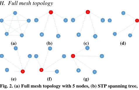
Fig. 2. (a) Full mesh topology with 5 nodes, (b) STP spanning tree, (c-g) Our model shortest paths with each root node.
In full mesh topology, each node has to direct links to every other nodes in the topology network. Here, we can consider a full mesh network with n nodes, with n > 2. In Fig. 2a, we have a full mesh network with 5 nodes. All costs associated to the links are assumed the same value.
Relative efficiency: For the full mesh topology shown in Fig. 2a, STP generates as a star topology. According to equations Eqs. (4), (5), the routing cost in general case of spanning tree protocol when we have n (n > 2) nodes is:
1 2
2 1 ( 1) 2 1 1
n
CSTP n A A n
e
(11)
When we apply our model, each node becomes a root node, and the shortest path from root node to another node in network looks like a star topology, as shown from Fig. 2c to Fig. 2d. According to the Eqs. (3), (4), (5), we can calculate the routing cost of our graph model in general case as:
( , ) ( , ) ( , ) ( 1)
, 1 1
n n
Cmodel d u v l i j i j An n
u v i j
(12)
Base on Eqs. (11), (12), the ratio of relative efficiency
between our model and STP is CSTP Cmodel
. In here, we
have4 2
3 , with n > 2.
Fig. 3 indicates a comparison between STP cost (CSTP) and our proposed model cost (Cmodel) in full mesh topology for various number of nodes (3 – 100 nodes). In here we assumed A = 1. From the result ofand Fig. 3, when the number of nodes in a full mesh topology is increasing, the relative efficiency of our proposed model is more improve than STP. The min value of ratio ρ is 4/3 and the max value is 2 in infinity. This means the routing cost of our proposed model is 0.25% less than STP in the worst case and is about 0.50% for large-scale networks.
Link and switch utilization: In full mesh topology, the number of logical link in network is L = n(n-1)/2. Here for simplicity, we assume the bandwidth of all link in network bk = b, and buffer capacity of all switch in network ck = c. Aside from this, we assume that the traffic demand between each pair of nodes is equal to d. Hence, in STP, the total amount of traffic load in each link lk is equal to (n-1)d. According to Eqs. (7), (8), the average utilization of links in STP is:
1
2 ( 1) 2( 1)
( 1) 1
n n d n d
l
STP n n k b n b
(13)
( 1) 2 1 22 ( 1) 2 2
( 1) 1
n n
n n d
l l
lSTP n n k b STP k n STP
(14)
In our proposed model, each link carries the data traffic from root node to destination node; therefore, lk = 2d. So, according to Eqs. (7), (8), we have:
( 1) 2
2 2 2
( 1) 1 n n
d d
l
model n n k b b
(15) ( 1) 2 2
2 2 2
2 0
( 1) 1 n n
d d
lmodel n n b b
k
(16)
Fig. 3. Comparison relative efficiency between STP and our proposed model in full mesh topology.
Similar, with switch utilization, in STP, the total amount of traffic load in each leaf switch is equal to (n-1)d, and the traffic on the root switch is equal to (n-1)(n-1)d. But in our proposed model, sk = (n-1)d. Hence, we have:
1 1 ( 1)2 ( 1)
1
n d
s n n
STP n k c
(17)
2
2 1
1
2 ( 1)2 ( 1)
1 n
d d
n s n s
STP n c STP c STP
k
(18)
1 ( 1) 1
n n d
s
model nk c
(19)
2 1
( 1) 0
1
n d
smodel n smodel
nk c
[image:6.612.49.287.122.276.2] [image:6.612.345.560.234.288.2] [image:6.612.344.563.337.514.2] [image:6.612.347.560.600.704.2]International Journal of Emerging Technology and Advanced Engineering
Website: www.ijetae.com (ISSN 2250-2459,ISO 9001:2008 Certified Journal, Volume 4, Issue 2, February 2014)
719
In Figs. 4, 5, we assume the value to calculate the variance for full mesh topology as d = 1, b = 103, c = 106. In these figures, the both variances in our proposed model as less than STP. Therefore, the average of link utilization of our model is greater than STP, and the load balancing of network is improved by our approach.
Average number of hops: In a full mesh topology, the average number of hops for STP is equal to:
( 1) Htotal H
STP n n (21)
Where n(n-1) is the total number of node pairs and Htotal is the total number of hops between all node pairs
in the network. Htotal can be obtain simply as shown
below:
( 1) 1 ( 1) [1 2( 2)]
total
H n n n (22)
From Eqs. (21), (22), we have:
2(n 1) HSTP
n
(23)
In our proposed model, all of the paths between nodes are only 1 hops, so that, the average number of hops of our model in full mesh topology isHmodel1. So that with n ≥ 3,
Eqs. (22), andHmodel the average number of hops in our
model is always less than STP. It means our proposed can reduce the average end-to-end delay in the network.
Bandwidth blocking probability: In the full mesh topology of our paper, we assumed it has n nodes and the same links with bandwidth equal to b. Hence, the total
bandwidth capacity of the networks is ( 1)
2 n n Ctotal b.
It is further assumed that there is a request for r units of bandwidth between arbitrary nodes i and j. This process will put an amount of traffic on the path from i to j. As we mentioned in 4.1.4, r is very small compared to b. In average, the total amount of traffics routed on the links for this request isr H . We repeat this request between node pairs until the total amount of requested bandwidth is equal to the total bandwidth capacity of network. In STP, we have the total amount of successfully routed bandwidths on (n-1) active links asB Hu STP (n 1)b. Therefore, the total
amount of rejected bandwidth is ( 2)
2 n n
BrCtotalBu b, and
the Bandwidth blocking probability (BBP) of STP is calculated as:
2
1
r STP
total
B n
BBP
C n
(24)
With n ≥ 3, BBPSTP have minimum value 1/2 and
maximum value 1 when n is reached to infinity.
Similar to the above equations, we can calculate the BBP for our proposed model in full mesh topology:
( 1) 2 n n
Ctotal b (25)
( 1) 2 n n
B Hu model b (26)
With Eqs. (26), we have:
0
BrCtotalBu (27)
Therefore, the blocking bandwidth probability of our proposed model in full mesh topology is zero. This is an expected result because in full mesh topology, we assume all of physical links are symmetric and have the same bandwidth capacity.
[image:7.612.346.546.325.443.2]Fig. 4. Comparison between STP and our proposed model of the variance of link utilization in full mesh topology.
Fig. 5. Comparison between STP and our proposed model of the variance of switch utilization in full mesh topology.
I. Partial mesh topology
International Journal of Emerging Technology and Advanced Engineering
Website: www.ijetae.com (ISSN 2250-2459,ISO 9001:2008 Certified Journal, Volume 4, Issue 2, February 2014)
720
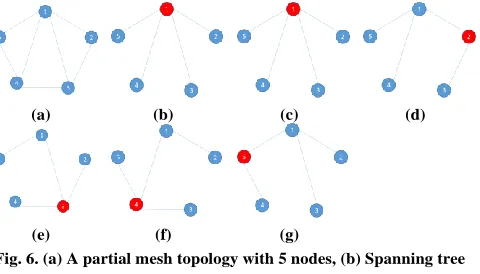
In our case, we consider an n-nodes partial mesh topology with a ring connect all nodes together and one node is connected to another nodes, and we assume that all links have the same cost equal to A. In Fig. 6, we show an example for this topology with n = 5.
(a) (b) (c) (d)
(e) (f) (g)
Fig. 6. (a) A partial mesh topology with 5 nodes, (b) Spanning tree protocol, (c-g) Our proposed model.
Relative efficiency: With the assumed topology, the generated tree of STP is also the star topology. For general, we assume node 1 connected with another nodes in network. In the case of 5 nodes, it is shown in Fig. 6b. Hence, the STP routing cost is also the same as the full mesh topology:
2 2 ( 1)
CSTP A n (28)
When we apply our proposed model, our topology can be shown from Fig. 6c to Fig. 6g. In case of root node 1, the topology is the same with STP. But with another nodes, we have:
1
(2 2 ( 3)) 2 ( 1)( 2) 1
n
Cmodel1 A A n A n n
i
(29)
So that, the total routing cost of our proposed topology is:
2 ( 1) 2 ( 1)( 2) (2 5 3) 1
Cmodel C Cmodel1A n A n n A n n
(30)
Fig. 7 shows a comparison between STP routing cost and our proposed model routing cost in partial mesh topology. In here, for clearly, we choose the number of nodes in partial mesh topology from 3 to 50 nodes.
From Eqs. (29), (30), we have the relative efficiency of our proposed model as ρ=CSTP/Cmodel. As the result, with n
[image:8.612.340.543.124.245.2]≥ 3, Cmodel is always greater than CSTP. It means our proposed model has the routing cost is less than STP in partial mesh topology.
Fig. 7. Comparison between STP and our proposed model in partial mesh topology.
Link and switch utilization: For the assumed partial mesh topology, according Eqs. (7) and (9), the average link and switch utilization in STP can be calculated as:
1
1 ( 1)
2 3 1
n n d
lSTP
n k b
(31)
1 1 ( 1)2 ( 1)
1
n d
s n n
STP n k c
(32)
According Eqs. (8) and (10), the variance of the link and switch utilization in STP are equal to:
21 2 3
1 2
2 ( 1)
2 3 1 1
n d n
n l l
lSTP n b
k k
(33)
2 1 2
1
2 ( 1)2 ( 1)
1 n
d d
n s n s
sSTP n c c
k
(34)
[image:8.612.52.292.184.321.2] [image:8.612.340.559.397.576.2]International Journal of Emerging Technology and Advanced Engineering
Website: www.ijetae.com (ISSN 2250-2459,ISO 9001:2008 Certified Journal, Volume 4, Issue 2, February 2014)
[image:9.612.69.275.125.244.2]721
Fig. 11. Comparison Variance of switch utilization between STP and our proposed model.
For our proposed model, we have:
2 3 2
1
(2 4) ( 1) 2
2 3 1 1 1
n n d
lmodel n n
n k k k b
(35)
2
2
21 2 3 2
2 2
( 2 4 ) ( 1)
2 3 1 1 1
n n
d d d
n l n l l
lmodel n k b model k b model k b model
(36)
11 2( 2) ( 3)2 ( 1) 1
n d
s n n n
model n k c
(37)
2 1 21
2 2
2( 2) ( 3) ( 1) 1
n
d d
n n s n s
s n c model c model
model k
(38)
In Figs. 10, 11, we assume the value to calculate the variance for full mesh topology as d = 1, b = 103, c = 106. In these figures, the both variances in our proposed model as less than STP. Therefore, the average of link utilization of our model in partial mesh topology is greater than STP, and the load balancing of network is improved by our approach.
Average number of hops: In full mesh and partial mesh network, the topologies created by STP are the same; therefore, the average number of hops for STP in this case is the same as full mesh topology:
2(n 1) HSTP
n
(39)
In the case of our proposed model in partial mesh topology, the average number of hops is calculated by:
2
2 3 3
( 1)
n n
Hmodel n n
(40)
[image:9.612.57.289.286.393.2]From Eqs. (39), (40) and Fig. 12, we can see clearly that our proposed model reduced the number of hops compared with STP. It means our model can reduce the average end-to-end delay in the network.
Fig. 12. Comparison between STP and our proposed model of the average number of hops in partial mesh topology.
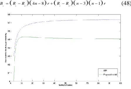
Bandwidth blocking probability: In the partial mesh topology of our paper, we assumed it has n nodes and the same links with bandwidth equal to b. This topology has the total number of physical links (2n-3). Hence, the total bandwidth capacity of the networks is:
(2 3)
total
C n b (41)
We repeat a request generation between arbitrary node pairs with r request until it reaches the physical bandwidth capacity of the network. At the end of this process, we have the following balance equation as:
( 1)
u STP
B H n b (42)
From Eqs. (41), (42), the total amount of rejected bandwidth is:
3 6 2 n
BrCtotalBu b (43)
So that, bandwidth blocking probability of STP in partial mesh topology is:
3 6 4 6 Br n BBP
STP Ctotal n
(44)
For our proposed model in this topology, assume a request for r units of bandwidth between all node pairs in each round. Repeat the rounds until total amount of requested bandwidth is equal with the bandwidth capacity of network. When we can reach this goal, the number of rounds (R1) will be:
2 3 1 ( 1) ( 1)
Ctotal n b R
n n r n n r
(45)
International Journal of Emerging Technology and Advanced Engineering
Website: www.ijetae.com (ISSN 2250-2459,ISO 9001:2008 Certified Journal, Volume 4, Issue 2, February 2014)
722
2 2( 2) b R
n r
(46)
Continue, after R3 rounds, other links will be saturated with (n-1)r data traffics carried at each round. Saturation of these links will block the data traffic between (n-3)(n-1) node pairs. We have:
3 ( 1) b R
n r
(47)
After R4 rounds, all the links will be saturated. In here,
R4=b/2r. With n ≥ 3, R4 > R1 > R3 > R2, and the rejected bandwidth is:
1 2 4 8 1 3 3 1
r
[image:10.612.62.285.272.423.2]B R R n r R R n n r (48)
Fig. 13. Comparison between STP and our proposed model of the bandwidth blocking probability in partial mesh topology.
So that, the bandwidth blocking probability of our proposed model in partial mesh topology is:
3 2 11 15 ( 1)(2 3)
n n n
BBPmodel
n n n
(49)
From Eqs. (49), and Fig. 13, it is clear that the bandwidth blocking probability of our proposed model in the partial mesh topology is smaller than its value in STP.
V. CONCLUSION
In this paper, we introduced a new forwarding strategy for Ethernet networks and its larger topology, Metro Ethernet networks. Our proposed model used some existing infrastructures of current Ethernet networks, based on exchange information of BPDU frames to establish the shortest path from any nodes to every other nodes of networks. With our model, the infinite loop is reduced. Additional, we overcome the low utilization of links and switches in network, provide a fast recovery time when network has been changed.
The advantage of our model is its simplicity. To show the effectiveness of the proposed approach, we compared analytically our model and Spanning Tree Protocol for two common topologies: full-mesh and partial-mesh. We showed that using proposed model instead of STP improves the relative efficiency by decreasing the routing cost, bandwidth blocking probability and the variances of link and switch utilizations.
Even our proposed model had better performance than the STP in the considered topologies, we need to consider more scenarios in future work to determine the capacities of our model when apply it in current Ethernet networks and Metro Ethernet networks. In this paper, we only used the Constant Bit Rate and uniformly distributed traffic. As a future work, some popular realistic traffic models must be considered to apply in more realistic Metro Ethernet topologies.
REFERENCES
[1] Metro Ethernet Forum, Metro Ethernet Services for Enterprises, October 2002.
[2] IEEE Std. 802.1d, 802.1D Standard for local and metropolitan area networks – Media Access Control (MAC) Bridges, IEEE, 2004. [3] M. Huynh, and P. Mohapatra, ―Metropolitan Ethernet networks: a
move from LAN to MAN,‖ Computer Networks. [Online]. Available: http://dl.acm.org/citation.cfm?id=1294622.
[4] IEEE Std. 802.1w, Rapid Reconfiguration of Spanning Tree, IEEE, 2004.
[5] IEEE Std. 802.1s, Multiple Spanning Trees, IEEE.
[6] A. Iwata, Y. Hidaka, M. Umayabashi, N. Enomoto, and A. Arutaki, ―Global Open Ethernet (GOE) System and its performance evaluation,‖ IEEE J. Select. Areas Commun., Oct. 2004.
[7] G. Ibanez and A. Azcorra, ―Alternative Multiple Spanning Tree Protocol (AMSTP) for Optical Ethernet Backbones,‖ LCN’04, Mar. 2004.
[8] S. Sharma, K. Gopalan, S. Nanda, and T. Chiueh, ―Viking: A multi-spanning-tree Ethernet architecture for metropolitan area and cluster network,‖ in Proc. INFOCOMM 2004, Mar. 7-11, 2004.
[9] T.L. Rodeheffer, C. A. Thekkath, and D. C. Anderson, ―Smartbridge: A scalable Bridge Architecture,‖ Sigcomm 2000, 2000.
[10] K. Lui, W. Lee, and K. Nahrstedt, ―STAR: A Transparent Spanning Tree Bridge Protocol with Alternate Routing,‖ ACM SIGCOMM 2002, July 2002.
[11] IEEE 802.1aq Task force Std., Virtual Bridged Local Area Network – Amendment 20: Shortest Path Bridging, IEEE, 2012.
[12] TRILL, Transparent Interconnection of Lots of Links (TRILL) working group charter, IETF, 2006.
[13] IEEE Std. 802.1q, Media Access Control (MAC) Bridges and Virtual Bridged Local Area Networks, IEEE, 2011.
International Journal of Emerging Technology and Advanced Engineering
Website: www.ijetae.com (ISSN 2250-2459,ISO 9001:2008 Certified Journal, Volume 4, Issue 2, February 2014)
723
[15] F. Faghani, and G. Mirjlily, ―Shortcut Switching Strategy in Metro Ethernet networks,‖ Computer Communications. [Online]. Available: http://dl.acm.org/citation.cfm?id=1968481.
[16] M. Huynh, and P. Mohapatra, ―A Scalable Hybrid Approach to Switching in Metro Ethernet Networks,‖ Presented at 32rd IEEE Conference on Local Computer Networks. [Online]. Available: http://ieeexplore.ieee.org/xpls/abs_all.jsp?arnumber=4367873&tag= 1.
[17] A. Meddeb, ―Smart spanning tree bridging for Metro Ethernets,‖ Presented at 33rd IEEE Conference on Local Computer Networks.
[Online]. Available: