ISSN: 1992-8645 www.jatit.org E-ISSN: 1817-3195
474
PERFORMANCE ANALYSIS OF COOPERATIVE
COMMUNICATION SYSTEMS USING WIRELESS OPEN
ACCESS RESEARCH PLATFORM
FOR INDOOR AND OUTDOOR ENVIRONMENT
1SUWADI, 2TITIEK SURYANI, 3IDA ANISAH
1,2,3
Department of Electrical Engineering, Institut Teknologi Sepuluh Nopember (ITS) SURABAYA, INDONESIA, 60111
3
Department of Electrical Engineering, Politeknik Elektronika Negeri Surabaya (PENS) SURABAYA, INDONESIA, 60111
E-mail: [email protected], [email protected], [email protected]
ABSTRACT
Effect of multipath fading can decrease the performance of wireless communication systems. The multi-input multi-output (MIMO) technique, which uses multiple antennas, often used to overcome multipath fading. This technique is one of the diversity techniques. Some wireless devices have limitation about the size, cost, and hardware complexity, so there can not implement a multiple antenna. Then, new technique has been developed to overcome these limitations, there was called cooperative communication systems. Although the cooperative communication system has been widely studied, but it was not much researcher already implemented this system. Therefore, this study will be conducted a simulation and implementation of cooperative communication system on Wireless Open Access Research Platform (WARP) module using Demodulate and Forward relaying techniques with Maximum Ratio Combining (MRC) and Selection Combining (SC). In this research will compare the performance of cooperative communication system with non-cooperative communication system, i.e. Single Input Single Ouput (SISO) and multi-hop to evaluate the BER performance as function of the transmit power and distance variation. At the first scheme of BER measurement, the distance between the source and the destination was fixed as 6 meters, relay was right in the middle, and the transmit power be varied from -39.67 dBm to -11.47 dBm. In the second scheme, the transmit power was be adjusted -39.67 dBm, the distance between the source and destination in a variation of 1 meter to 6 meters. The results of measurement showed that cooperative communication system with MRC better than SISO communication systems, multi-hop communication and cooperative communication system with SC for indoor or outdoor environment.
Keywords: Cooperative Communication System, Relay, Demodulate And Forward, MRC, SC, WARP
1. INTRODUCTION
Currently, the development of communication technology is very rapidly. Many communications equipment that uses wireless media has many advantages, i.e. a simple and a high mobility. In implementation of wireless communication system has many challenges, such as a signal is transmitted over wireless communication, a signal will have a lot of interference that can degrade system performance. Channel conditions will decline so that channel capacity and reliability of the transmitted data is also decreased. Multipath fading
is the most dominant effect in the wireless communication system.
475 distributed to improve the overall performance of wireless networks [3]. In the cooperative communication systems, source (S) sends information broadcast to destination (D) and to relay (R) which is another user nearby. Therefore the signal received by R will be processed and then sent to D. The signals are received from the source or relay will undergo a process of combining on the destination side [4].
Research on cooperative communication system was widely studied [1-2] [5-6]. On the paper provides a very good overview of the theory of cooperative communication systems. Although the cooperative communication system has been widely studied, little research that implements the system. Thus, the problems associated with implementation are still not well understood.
There are a wide range of platforms used to implement cooperative communication systems. In [7] the authors use software-define-radio platform that is used for the design of physical layer (PHY). There is still a shortage if you use that platform, i.e. the software implementation of the physical layer does not work in real time. As for the other platforms that can be used is the GNU Radio project. The project provides a flexible platform for wireless development, which includes open-source framework from wireless algorithms are implemented in software. With most of the processing is executed the PC host, the GNU Radio
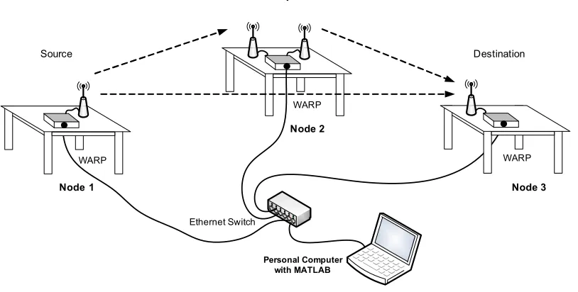
One platform that can improve the deficiencies of the previous platform was WARP. Wireless Open-Access Research Platform (WARP), a FPGA module that has been prepared to implement advanced wireless algorithms. This platform has many advantages, WARP is made with special hardware design, integrate resources FPGA-based processing with real radio interface. Moreover this platform is supported by a special module that allows users of various processing hardware and peripheral resources. The platform also supports the modules used to build a variety of research applications, including real-time implementation of the physical layer and MAC layer [9-11]. Therefore, in this study the authors will implement cooperative communication system in the Wireless Open Access Research Platform (WARP). This research demonstrated the performance of cooperative communication systems in indoor and outdoor environments. Indoor measurements will be performed in Building B303 and outdoor measurements performed in the parking lecturer of the Department of Electrical Engineering Institute of Technology - Surabaya.
The paper begins with a brief description of research background in introduction section. Section II describes research methode. Section III explains implementation results and analysis. Finally, a summary is given in the last section.
Personal Computer with MATLAB
Ethernet Switch
WARP
Relay
Node 2
Node 1
WARP
Source
WARP
Destination
[image:2.612.105.512.497.703.2]Node 3
ISSN: 1992-8645 www.jatit.org E-ISSN: 1817-3195
476
WARP Node 2
Downconveter with Baseband
Downsample dan Correlator
Demodulasi DQPSK
Data Modulasi
DQPSK Preamble Adder Upsample With SRRC Upconveter with
Baseband WARP Node 2
WARP Node 3
Downconveter with Baseband
Downsample dan Correlator
Demodulasi DQPSK
Data SC or MRC WARP
Node 1
Upconveter with Baseband
Upsample With SRRC
Preamble Adder
Modulasi DQPSK
Generate bit
Relay
[image:3.612.90.524.90.444.2]Source Destination
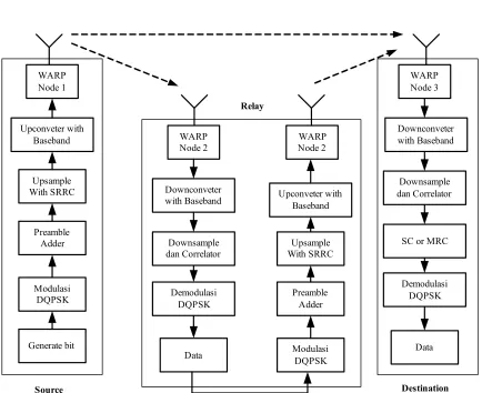
Figure 2: Cooperative Communications System Block in WARP
2. SYSTEM MODEL AND RESEARCH
METHODE
In the cooperative communication systems, source (S) relay that information broadcast to destination (D) and to relay (R) which is the other users in the area are close by. Then the signal received by R will be processed first and then sent to D. The signals received from the sender or from the relay will experience the process of combining in the receiver [4]. Implementation of the WARP cooperative communication system will be described as shown in Figure 1.
Cooperative communication systems operating under the protocol Time Division Multiplexing (TDM) in which the source transmits data during the first slot and the relay transmits during the second. The data which is transmitted during the first time slot is received by the relay and the destination node. In this study the type of relay used is demodulate and forward.
This implementation is performed on the module WARP is an FPGA module that has been prepared to implement advanced wireless algorithms. The communication system described in this paper using such a PC-based version of WARP MATLAB called WARPLAB. WARP-based cooperative communication system is designed to use a modulation technique Differential Quadrature Phase Shift Keying (DQPSK). By using DQPSK modulation, does not require phase synchronization at the receiver because DQPSK is a non-coherent modulation technique. Figure 2 is a block diagram design to the implementation of cooperative communication system in WARP.
477 In the relay (node 2), the signal undergo the reverse process from the source (node 1) is down converter, down sample, and demodulation. Furthermore, the signal is transmitted to the destination (node 3). At the destination (node 3) receives two signals, the signals are from the source and the signal from the relay. Both of these signals will undergo a process of combining. The combining technique used is Selection Combining (SC) and Maximum Ratio Combining (MRC).
At techniques Selection Combining (SC), there was selected the best signal from all of the received signal in destination. This selection was based on the value of the Receive Signal Strength Indicator (RSSI) which is the biggest in accordance with equation (1)
,
, (1)
As for the technique Maximum Ratio Combining (MRC), the both signal was summed as Equation (2):
(2)
where :
yd[n] : MRC output signal in destination RSSIS : RSSI of received signal from source RSSIR : RSSI of received signal from relay
: received signal from source
: received signal from relay
After combining process, the receiver will do the reverse process of that performed by the transmitter. As these stages are down converter, filters Squared Root Raised Cosine (SRRC) at the receiver and down sampling. To detect the location of the preamble, correlation process is carried out with reference matrix that has been generated on the receiver. After that, on the end stage, it demodulates the DQPSK signal to obtain estimates of the received signal. Furthermore, the received signal compared to the signal sent to count the value of the bit-error-rate of system.
3. IMPLEMENTATION RESULTS AND ANALYSIS
[image:4.612.315.521.137.283.2]In the Chapter III contains the results of simulation and analysis, which includes the
Table:1 Simulation Parameter
No. Parameter
Specification
1. Number of bit 211 2. Modulation scheme DQPSK 3. Filter type SRRC 4. Number of preamble 13 5. Number of sample 8 6. Sample Frequency 40 MHz 8. Carrier Channel 12 [0-14] 9. Transmitter baseband gain 0 [0-3] 10. Transmitter RF gain 0-63 11. Receiver baseband gain 0 [0-31] 12. Receiver RF gain [1-3]
3.1 Implementation Results of Cooperative Communication System on WARP Module
In this implementation of cooperative communication systems, relay is used to the demodulation process, then it forwards signal to destination. In Figure 3 will be shown in the signal forms sent from the source and received.
[image:4.612.316.519.530.688.2]Based on the WARP specifications that signal input at the transmitter buffer must be between the amplitude of -1 and 1. As explained earlier that the cooperative communication system is two paths, the direct path (source - destination) and the path through the relay (source - relay - destination). Figure 3 shows the signal to be transmitted by the source with the amplitude level between -1 and 1. It also shows the signal received by the relay. Based on these images can be seen that the signals arriving at the relay delayed and decreased amplitude.
Figure 3:(a) Baseband Signal from Source, (b) Received Baseband Signal in Relay
0 1 2 3 4 5 6
x 10-6 -1
-0.5 0 0.5 1
Waktu (detik)
A
m
p
lit
u
d
e
Real Imajiner
4 5 6 7 8 9 10 11
x 10-6 -1
-0.5 0 0.5 1
b
Waktu (detik)
A
m
p
lit
u
d
e
Real Imajiner
(a) Time (sec)
ISSN: 1992-8645 www.jatit.org E-ISSN: 1817-3195
478
Figure 4: (a) the Baseband Signal Sending by Relay, (b) Baseband Signal Received by Destination
Figure 5: (a) Baseband Signal Sent by Source, (b) Baseband Signal Received by Destination (direct link)
Because the relay is used Demodulate and Forward, then the relay undergo demodulation process before hand. After the demodulated signal is modulated so that the signals sent back by the relay resembles the signal transmitted by the source, then the signal will be sent to the destination. The image signal sent by the relay and received by the destination shown in Figure 4.
[image:5.612.87.531.49.513.2]Figure 4 shows that the signals sent by the relay resemble the signal sent by the source because in the relay has demodulation and modulation processes. Not only that the signal received by the destination even resemble the signal received by the relay. In direct path (source - destination), distance between the source to destination twice the distance of the source to relay or relay to destination. The signal form is sent by the source to the destination with a direct path or no relay is shown in Figure 5.
Figure 6: Performance of Cooperative Communication System for various Taransmit Power in Indoor
Environment
Figure 7: Performance of Cooperative Communication System for various Taransmit Power in Outdoor
Environment
Based on Figure 5, it can be seen that received signal by the destination was smaller and the delay was greater in the direct path than if through a relay. Based on the signal form, the use of the relay is more profitable than a direct path.
3.2 Analysis of Implementation Results on
WARP for Various Transmit Power
In this section, it compared to the three systems that have been implemented i.e. SISO communication system, multi-hop and cooperative communication system. The cooperative communication system will be evaluated to use two combining techniques, by using Selection Combining (SC) and Maximum Ratio Combining (MRC). Performance of system will be evaluated
0 1 2 3 4 5 6
x 10-6 -1 -0.5 0 0.5 1 Waktu (detik) A m p lit u d e Real Imajiner
4 5 6 7 8 9 10
x 10-6 -1 -0.5 0 0.5 1 b Waktu (detik) A m p lit u d e Real Imajiner
0 1 2 3 4 5 6
x 10-6 -1 -0.5 0 0.5 1 a Waktu (detik) A m p lit u d e Real Imajiner
6 7 8 9 10 11
x 10-6 -1 -0.5 0 0.5 1 b Waktu (detik) A m p lit u d e
-40 -38 -36 -34 -32 -30 -28 -26 -24 -22 -20 10-4
10-3 10-2 10-1 100
Daya Pancar (dBm)
B E R SISO Multihop SC MRC
-40 -38 -36 -34 -32 -30 -28 -26 -24 -22
10-4 10-3 10-2 10-1 100
Daya Pancar (dBm)
B E R SISO Multihop SC MRC
Transmit Power (dBm)
Transmit Power (dBm) (a) Time (sec)
(b) Time (sec)
(a) Time (sec)
[image:5.612.92.298.299.463.2] [image:5.612.319.520.327.495.2]479 meters, and relay is right down the middle. This measurement is performed in indoor and outdoor environments.
Based on Figure 6, it can be seen that the cooperative communication system using Maximum Ratio Combining (MRC) is better than non-cooperative communication systems (SISO), multi-hop communications system or a cooperative communication system using Selection Combining (SC). For example, Indoor environment, the transmit power of -35.19 dBm, the SISO communication system has Bit Error Rate (BER) at 6.25 x 10⁻². In the multi-hop communication system and the system of cooperative communication system using Selection Combining (SC), its value is almost the same BER is1.2 x 10-2 and2.27 x 10-2 dBm, while the value of BER in cooperative communication system using Maximum Ratio Combining (MRC ) is 1.4 x 10⁻³. Only by using the transmit power of -32.39 dBm in cooperative communication system using Maximum Ratio Combining (MRC) have been achieved BER value of 0, in other words all the data received there were no errors. As for the multi-hop and SISO communication system get BER is equal to 0 at the transmit power -20.3395 dBm and -23.5975 dBm.
Performance of multi-hop communication system is similar to the cooperative communication system using a type Selection Combining (SC). The cooperative communication system with Selection Combining (SC) selects one of the signals that have the greatest SNR between direct path with via relay (multi-hop). It is assumed that nodes are not moving. Signal on direct channel is worse than the multi-hop. A cooperative communication system using Selection Combining (SC) always chooses the signal from multi-hop channel so that the performance of cooperative communication system using Selection Combining (SC) is almost the same as multi-hop communication system. If seen the results of the implementation of the BER values of communication system using Selection Combining (SC) is not much different to the multi-hop communication system. For example the transmit power of -39 672 dBm, BER value at multi-hop communication amounted to 7.87 x10⁻² while cooperative communication system using Selection Combining (SC) is 8.35 x 10⁻². Based on Figure 3, power transmit values also affect the value of BER where for the transmit power increases, so BER value of system decrease. In addition to the analysis conducted in the indoor environment, the analysis
In general, it can be seen that performance of the SISO, multi-hop and cooperative communication system in outdoor environments showed a similar pattern to the indoor environment in which the cooperative communication system using Maximum Ratio Combining (MRC) is better than SISO, multi-hop and cooperative communication system using Selection Combining (SC).
3.3 Analysis of Implementation Results on
WARP for VariousDistance
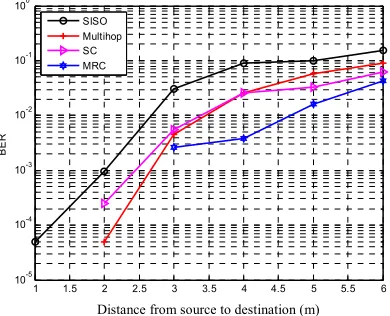
In this section, the system performance is evaluated for the condition of transmit power remains while the distance between the source and destination are made varies. The result can be seen in Figure 8 and 9. In the figure can be seen that the distance between the source and destination affects BER values. For example in the cooperative communication system using Maximum Ratio Combining (MRC), at a distance of 1 meter BER its value at 0, while at a distance of 3 meters BER value for 2.58 x 10⁻³. Thus the greater the distance between the source and destination, the BER values are also getting bigger. At figure 8, there is a comparison curve between SISO communication systems, multi-hop and cooperative in indoor environments and figure 9 is in outdoor environments.
Figure 8: Performance of Cooperative Communication System for various distances in Indoor Environment
1 1.5 2 2.5 3 3.5 4 4.5 5 5.5 6
10-5 10-4 10-3 10-2 10-1 100
Jarak S-D (meter)
B
E
R
SISO Multihop SC MRC
[image:6.612.320.515.456.614.2]ISSN: 1992-8645 www.jatit.org E-ISSN: 1817-3195
480
Figure 9: Performance of Cooperative Communication System for various distances in Outdoor Environment
4. CONCLUSION
Implementation of SISO communication systems, multi-hop and cooperative communication systems on WARP with relay Demodulate and Forward and techniques Selection Combining (SC) and Maximum Ratio Combining (MRC) is done using the framework WarpLab that integrate between Matlab and WARP modules. In this paper used three modules WARP as the source, relay and destination. In this implementation was analyzed the performance of each system to see the value of BER as a function of the transmit power and distance.
Based on measurement results, cooperative communication system using MRC is better than SISO communication system, multi-hop and cooperative communication system using SC. For example the transmit power of -35.19 dBm, the BER value of SISO communication system of 6.25x10⁻². In the multi-hop communication system and cooperative communication system using SC are almost the same of BER 1.2x10⁻² and 2.7x10⁻², while the value of BER in cooperative communication system using Maximum Ratio Combining with MRC is 1.34x10⁻³. Only by using the transmit power of -32.39 dBm, cooperative communication system with MRC has achieved BER value of 0. As for multi-hop communication system and SISO have achieved BER value equal to 0 at power transmit -20.3395 dBm and -23.5975 dBm.
These measurements were not only indoor but also outdoor area. Cooperative communication system using MRC at -35.19 dBm transmit power in the indoor area had BER value 1.34x10⁻³, where
as in the outdoor of 1.1x10⁻³. BER value is also influenced by the value of transmit power and the distance between the source and destination. The greater the value of the transmit power, the value of BER gets smaller while the greater the distance between the source and destination, the greater its value BER.
5. ACKNOWLEDGMENTS:
6.
This work was financially supported by a Research Grant from the Indonesian government through the ministry of research - technology and higher education with PUPT research scheme.
REFRENCES:
[1] A. Sendonaris, E. Erkip, and B. Aazhang, “User cooperation diversity—Part I: System description,” IEEE Trans. Commun., vol. 51, no. 11,pp. 1927–1938, Nov. 2003.
[2] A. Sendonaris, E. Erkip, and B. Aazhang, “User cooperation diversity—Part II: Implementation aspects and performance analysis,” IEEE Trans. Commun., vol. 51, no. 11, pp. 1939–1948, Nov. 2003.
[3] Patrick Murphy and Ashutosh Sabharwal,“ Design, Implementation, and Characterization of a Cooperative Communications System”, Transaction On Vehicular Technology, Vol. 60, No. 6, July 2011
[4] Su,W., Sadek,A.K., and Liu,K. J. R., “Cooperative Communication Protocols in Wireless Networks”, New Orleans, 2007 [5] G. Kramer, I. Mari´c, and R. Yates,
“Cooperative communications,” Found. Trends Netw., vol. 1, no. 3, pp. 271–425, Aug. 2006.
[6] K.Liu,A.Sadek,W.Su,andA.Kwasinski, Coopera tive Communications and Networking. New York: Cambridge Univ. Press, 2009.
[7] T. Korakis, M. Knox, E. Erkip, and S. Panwar, “Cooperative network implementation using open-source platforms,”Communications Magazine, IEEE, vol. 47, no. 2, pp. 134 –141, 2009.
[8] Patrick Murphy, Ashu Sabharwal, and Behnaam Aazhang, “Design of WARP: a Wireless Open-Access Research Platform,” 14th European Signal Processing Conference (EUSIPCO 2006), Florence, Italy, September 4-8, 2006.
[9] http://warp.rice.edu/trac/
1 1.5 2 2.5 3 3.5 4 4.5 5 5.5 6
10-3 10-2 10-1 100
Jarak S-D (meter)
B
E
R
SISO Multihop SC MRC
481 Networking: Technologies and System Design”, Springer New York Dordrecht Heidelberg London, 2010.
[11] A Nosratinia, A. Hedayat, and T.E. Hunter,”Cooperative Communication in Wireless Networks”, IEEE Communication Magazine, vol. 42,10, pp. 74-80, 2004. [12] Glenn J.Bradford and J.Nicholas Lanema,” An
Experimental Framework for the Evaluation of Cooperative Diversity”, Proc. C ISS , 2009, pp. 641–645
[13] Dirk van den Borne, “Robust Optical Transmission Systems” Technische Universiteit Eindhoven, Netherlands, 2008 [14] Nader Sheikholeslami Alagha and Peter
Kabal,”Generalized Raised-Cosine Filters”,IEEE Transactions on Communication, Vol. 47, No. 7, July 1999 [15] Michael Knox and Elza Erkip,
“Implementation of Cooperative Communication using Software Defined Radios” IEEE, October 2010