ISSN: 1992-8645 www.jatit.org E-ISSN: 1817-3195
DIRECT TORQUE CONTROL TECHNIQUE IN
INDUCTION MOTOR DRIVES - A REVIEW
1S ALLIRANI, 2V JAGANNATHAN
1 Associate Professor, Department of EEE, Sri Ramakrishna Engineering College
Coimbatore - 641022, Tamilnadu, India
2 Professor & Head (Rtd.), Department of EEE, Coimbatore Institute of Technology
Coimbatore - 641004, Tamilnadu, India E-mail: [email protected],
ABSTRACT
The aim of this paper is to review the origin and developments of direct torque control (DTC), an advanced
control technique of induction motor drives yielding superior performance. The direct torque control is one of the excellent control strategies available for torque control of induction machine. It is considered as an
alternative to field oriented control (FOC) technique. The DTC is characterized by the absence of PI regulators, co-ordinate transformations, current regulators and pulse width modulated signal generators.
DTC also allows a good torque control in steady state and transient operating conditions. In this paper, development of DTC is discussed. The DTC based on space vector modulation (SVM) and switching table
has been reviewed. With successively improving reliability and performance of digital technologies, digital
control techniques have predominated over analog techniques. Digital control techniques are carried out with microcontrollers, digital signal processors due to their software flexibility and low cost which are
being reviewed. Intelligent control techniques like neural networks (NN) and fuzzy logic based DTC are reviewed. Field Programmable Gate Arrays (FPGAs) are a useful platform for the implementation of high
bandwidth control systems and the role of FPGA on DTC based induction motor drive is also presented.
Keywords:
Direct Torque Control, Field Programmable Gate Array, Fuzzy Logic, Induction Motor, Space Vector Modulation, Neural Network1. INTRODUCTION
The Induction Machine (IM) has been widely used in industries due to its relative
cheapness, low maintenance and high reliability [1]. The control of IM variable speed drives [2],
[3] often requires control of machine currents,
which is achieved by using the Voltage Source Inverter (VSI). The scalar control of IM drives
with inverters is widely used in low cost applications. The main advantage of v/f control is
its simplicity and for this reason it has been traditionally implemented using low cost
microcontrollers. For those applications, which require higher dynamic performance than v/f
control, the dc motor like control of IM, referred to as Field Oriented Control (FOC) is preferred.
The main issue of FOC drive is how to obtain the decoupled control of machine flux and torque [4].
An indirect form of FOC is also used in IM drives, used in high performance applications. A new
concept of control, quite different from that of the FOC yielding quick response and high efficiency
in IM has been proposed and discussed in [5] - [7].
The key features of this method are 1) The proposed scheme is based on limit cycle control
of both flux and torque using optimum PWM output voltage; a switching table is employed for
ISSN: 1992-8645 www.jatit.org E-ISSN: 1817-3195 low an inverter switching frequency and as low
harmonic losses as possible. 2) The efficiency
optimization in the steady-state operation is also considered; it can be achieved by controlling the
amplitude of the flux in accordance with the
torque command. To verify the feasibility of this scheme, experimentation, simulation and
comparison with field-oriented control are carried out. The results prove the excellent characteristics
for torque response and efficiency, which confirm
[image:2.612.331.530.216.312.2]the validity of this control scheme.
Figure 1 Torque control schemes. (a) Field-oriented control. (b) Direct torque control [6]
Figure 1(a) shows typical system
configuration employing FOC. The system usually employs a position sensor to drive a
rotating reference frame transformation, which generates the phase current commands for the
current controlled inverter. The primary current
reference i* is calculated from the flux command
ψ* and the torque command T* by using an estimator. The control equation for the estimator contains motor parameters which vary with the
winding temperatures and the flux saturation level of the iron core. Fig. 1 (b) shows a schematic
diagram of the proposed control scheme. In the system, instantaneous values of the flux and the
torque are calculated from primary variables and
controlled by using an optimum switching table. Therefore, it can achieve not only the fastest
torque response but also the lowest harmonic losses and acoustic noise.
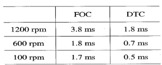
In [8] the performance of the two control schemes DTC and FOC is evaluated in
terms of torque and current ripple, and transient response to step variations of the torque command.
The analysis has been carried out on the basis of
the results obtained by numerical simulations, where secondary effects introduced by hardware
implementation are not present.
Figure 2 (a) Basic DFOC Scheme [8]
[image:2.612.104.289.286.409.2]Figure 2 (b) Basic DTC Scheme [8]
Table 1 Settling Time of the Torque Response
The analysis has been carried out on the basis of the results obtained by numerical
simulations, where secondary effects introduced by hardware implementation are not present.
Figure 2 (a) shows the direct field oriented control (DFOC) and Figure 2 (b) shows simple DTC. The
authors concluded that the whole performance of
the two schemes is comparable. DTC might be preferred for high dynamic applications [9], but,
[image:2.612.331.517.362.455.2] [image:2.612.340.501.513.578.2]ISSN: 1992-8645 www.jatit.org E-ISSN: 1817-3195 compensated by SVM based DTC scheme. The
DTC scheme is relatively simple to implement,
requiring a very small computational time when compared to FOC (Table 1).
In this review, a grouping of papers
based on the control strategy is attempted and shown in Table 2. DTC based on intelligent
control techniques like fuzzy logic and neural network is mainly used to reduce torque ripples.
DSP and FPGA based DTC are improving the performance of drives.
Table 2 Review Based on Control Techniques
Sl.No. Control Techniques References
1 Fuzzy logic based DTC [10] – [24]
2 NN based DTC [25] - [28]
3 FPGA based DTC [29] - [41]
4 DSP based DTC [42] - [47]
This paper is organized as follows: Section 2 review the development of DTC and
comparison of its performance with FOC. SVM based DTC is reviewed in section 3. Sections 4
and 5 reviewed the fuzzy logic and neural network based DTC respectively. FPGA and DSP
based DTC are reviewed in sections 6 and 7
respectively. Finally the paper is concluded in section 8.
2. PRINCIPLES OF DTC
DTC of an induction motor has been successful because it explicitly considers the
inverter stage and uses few machine parameters, while being more robust to parameter uncertainty
than field-oriented control (FOC). The papers [48] and [49] present a formal and theoretical
derivation of DTC based on singular perturbation
and nonlinear control tools respectively. The derivation elaborates an explicit relationship
between DTC performance and machine characteristics; low-leakage machines are
expected to perform better under DTC. The known troublesome machine operating regimes
are predicted and justified. Explicit conditions to guarantee stability are presented. Finally,
compensation strategies that extend DTC are discussed. The paper [50] presents a review of
recently used direct torque and flux control (DTC) techniques for voltage inverter-fed
induction and permanent- magnet synchronous
motors. A variety of techniques, different in concept, are described as follows:
switching-table-based hysteresis DTC, direct self control, constant switching frequency DTC with
space-vector modulation (DT'C-SVM). Also, trends in the DTC-SVM techniques based on
neuro-fuzzy logic controllers are presented.
Mechanical speed measurement used
to be an undesired necessity for inverter-fed IM. The paper [51] presents a possible way of
calculating the exact speed without mechanical
devices. The control scheme is based on the analog basic version of direct self control (DSC)
of inverter-fed induction machines and needs only a few additional operational amplifiers for
signal processing. In [52], [53], and [54], torque
control of an induction machine based on DTC strategy has been developed and a comprehensive
study is presented. The performance of this control method has been demonstrated by
simulations performed using a versatile simulation package Matlab/Simulink. Several
numerical simulations have been carried out in a steady state and transient operation on a speed
control mode.
2.1 Problems Associated With DTC
The main problems associated with
DTC are the well known torque ripples. Many papers presented different approaches to
minimize the torque ripples [55] – [62]. In [55]
and [61] flux linkage, electromagnetic torque are controlled directly by the selection of a switching
vector from a look-up table. However, the selected vector is not always the best one since
only the sector is considered where the flux linkage space vector lies without considering its
ISSN: 1992-8645 www.jatit.org E-ISSN: 1817-3195 flux and torque control method for DTC-based
IM drives, where the flux and torque errors are
geometrically put together to make a stator voltage vector in a deadbeat fashion. The look-up
table in the DTC is replaced by a
minimum-distance vector selection scheme to minimize the flux and torque ripples over a fixed
sampling period. Simulation and experimental results proved that the proposed algorithm
effectively reduces the flux and torque ripples. The paper [56] presents a new direct self-control
(DSC) scheme for IM drives using the stator voltage third harmonic component in order to
estimate the air-gap flux and the torque as well as
to synchronize the supply voltage vector. Compared to previous DSC schemes the new one
is independent from any motor parameter variation, specifically on stator resistance thus
showing better performances at low speeds. The paper starts with a quick review on standard DSC
main features pointing out the influence of stator resistance variations on the flux and torque
control. The new DSC scheme is then introduced
and evaluated by simulations and experimental tests on a 1.5-kW induction motor drive.
In [56] and [58] novel techniques for the DTC of an IM are proposed, which overcomes
the trouble of high torque ripple afflicting the conventional DTC technique. In [57] the inverter
voltage vector selected from the switching table is applied for the time interval needed by the torque
to reach the upper (or the lower) limit of the band,
where the time interval is calculated from a suitable modeling of the torque dynamics. By this
approach, the control system emulates the operation of a torque hysteresis controller of
analog type since the application time of the inverter voltage vector is dictated by the allowed
torque excursion and not by the sampling period. It is shown by experimental results that the
technique yields a considerable reduction of the
torque ripple. In [58] a constant switching frequency torque controller is proposed to replace
the conventional hysteresis-based controller. The
proposed controller is shown to be capable of reducing the torque ripple and maintaining a
constant switching frequency. In [59] the proposed HPWM method is developed based on
notion of stator flux ripple which can be used for
a measure of ripple in the line current. Expressions for mean square flux ripple, over a
sub cycle are derived for each switching sequence and this analysis together with the total harmonic
distortion (THD) performance of each sequence is used to develop the HPWM method for induction
motor drives. The proposed PWM method improves the performance of the drive in terms of
ripple at all modulation indices. In [60] a three
level SVM based DTC is proposed. A predictive torque control is proposed in [61] to reduce torque
ripples. In [62] a sliding mode controller is investigated which features in very low flux and
torque ripple. In order to guarantee electromagnetic torque and stator flux to track its
reference signal strictly, the electromagnetic torque sliding mode variable and stator flux
sliding mode variable were selected separately.
Furthermore, a robust stator flux observer is designed for sliding mode direct torque controlled
induction motor system. The design of state observer is based on regional pole assignment
theory. The observer gain matrix is obtained by solving linear matrix inequality (LMI) using LMI
Toolbox in MATLAB. Finally, the effectiveness and validity of the proposed control approach is
verified by computer simulation results.
2.2 Improvements Suggested on DTC
With conventional DTC some additional modifications are performed to
improve the performance of DTC. In papers referred under [63] – [84], certain advancements
on DTC are discussed and experimental results
are presented to indicate the gains as a result of them. Table 3 shows the references along with
modifications.
ISSN: 1992-8645 www.jatit.org E-ISSN: 1817-3195 presented, in which the principles of sliding-mode
control (SMC), DTC, and SVM are combined to
ensure high-performance operation both in the steady state and under transient conditions. In
particular the SMC contributes to robustness of
the drive, the DTC results in a fast dynamic response, and the SVM improves the torque, flux
and current steady-state waveforms by ripple reduction. The sliding-mode state observer of an
IM has been proved stable and accurate. Computer simulations and experimental results
presented demonstrate the robustness, accuracy, quickness, and low chattering, wide-speed-range
operation of the drive.
[image:5.612.84.299.356.726.2]In [64] a prediction scheme is presented to diminish both the torque and flux ripples in a DTC based IM drive.
Table 3 References Showing Improvements
Sl.No. Ref. Improvements
1 [83],
[84]
FEM based DTC
2 [65],
[66]
DTC with H-bridge inverter
3 [72] Improved stator flux estimation with low pass filtering
4 [75] DTC in transition region
5 [76] Extension of DTC
6 [69] DTC with dynamic
over-modulation
7 [70] DTC with different observers
8 [68] Model predictive DTC
9 [67] DTC for five phase drives with increased number of voltage
vectors
10 [64] DTC with prediction scheme
11 [82] DTC with matrix converter
12 [81] DTC using 12 sided polygonal voltage space vector
13 [77] Efficiency improvement in DTC
14 [78] DTC with multilevel inverters
15 [80] DTC with single current sensor
16 [71] DTC with Deadbeat controller
17 [74] DTC with unified flux controller
18 [73] Improved DTFC
19 [79] DTC for vehicles
20 [63] DTC with sliding mode
controller
In a discrete implementation of the classical DTC scheme, the time delay associated with data
processing results in additional torque and flux ripples. This part of the ripples can amount to a
significant fraction of the overall ripple if the
hysteresis bands are comparable to the maximum torque and flux variations in one sampling
interval. This paper presents a prediction scheme with low computational complexity and low
parameter sensitivity, both comparable to the standard DTC scheme. The papers [65], [66] and
[79] present a motor drive controlled by DTC for electric vehicles (EVs) or hybrid EVs. The stator
voltage vector reference is computed from the
stator flux and torque errors imposed by the flux and torque controllers. This voltage reference is
then generated using a hybrid cascaded H-bridge multilevel inverter, where each phase of the
inverter can be implemented using a dc source, which would be available from fuel cells,
batteries, or ultra capacitors. This inverter provides nearly sinusoidal voltages with very low
distortion, even without filtering, using fewer
switching devices.
As DTC is a variable-structure control
strategy with simplicity, fast response, and tolerance to motor parameter variation, which
provides direct control of stator flux and electromagnetic torque by optimally selecting the
inverter states in each sampling period, it is
preferred for five-phase drives in which the increased number of voltage vectors offers greater
flexibility in optimizing the selection of the inverter states, thereby accomplishing more
precise control of stator flux and torque [67]. Nevertheless, the large number of inverter states
means that a more elaborate and complex
ISSN: 1992-8645 www.jatit.org E-ISSN: 1817-3195 drives, are taken into account in designing
switching-table-based DTC for five-phase drives.
First the low-frequency harmonic currents due to the auxiliary vector plane need to be eliminated.
Second, full utilization of the dc-link voltage is
desired. A novel switching-table-based direct torque controller fulfilling these objectives is
proposed and is combined with a speed-adaptive variable-structure observer. For medium-voltage
drives, model predictive direct torque control (MPDTC) significantly reduces the switching
losses and/or the harmonic distortions of the torque and stator currents, when compared to
standard schemes, such as DTC or pulse width
modulation which is presented in [68]. In [70], two methods of speed estimation i.e. open and
closed loop observation method. It is observed that speed estimation is more reliable and more
efficient with closed loop observers which are expressed in the cases of dynamic behavior of' the
system. The disadvantage of this method is that, in practice, an increased amount of time is
required by microcontrollers. With open loop
estimators, system control for low speeds is problematic.
In [69] a dynamic over modulation strategy for fast dynamic torque control based IM
is proposed. The fastest dynamic torque response with a six-step mode can be achieved in the
proposed method by switching only the most optimized voltage vector that produces the largest
tangential component to the circular flux locus.
This paper also discusses the performance of dynamic torque control in basic DTC in order to
justify on how the proposed selected voltage vector results in excellent dynamic torque
performance. The main benefit of the proposed method is its simplicity, since it only requires a
minor modification to the conventional DTC-hysteresis- based structure and does not
require a space vector modulator. To verify the
feasibility of the proposed dynamic over modulation strategy, simulation and
experimentation, as well as comparison with the
conventional DTC scheme, are carried out. Results showed a significant improvement in the
dynamic torque response when compared to the conventional DTC hysteresis- based method.
In [71], properly formed discrete-time
recursive models of a stator and rotor flux-linkage observer are presented. A model delay in the
flux-linkage observer, which hindered previous work, is identified. To remove this delay, a new
stationary frame current observer is developed and experimentally verified. With this new
observer system, the flux linkages are properly estimated for the next sample instant, thus
removing the computational delay. The improved
and the delayed flux observer are evaluated in a deadbeat direct torque control algorithm. In [72]
an improved stator flux estimation technique based on a voltage model with some form of
low-pass (LP) filtering is presented. In voltage-model-based stator flux estimation, an LP
filter is normally used instead of a pure integrator to avoid integration drift problem due to dc offset,
noise, or measurement error present in the back
electromotive force. In steady-state condition, the LP filter estimator will degrade the performance
and efficiency of the DTC drive system since it introduced magnitude and phase errors, thus
resulting in an incorrect voltage vector selection. The stator flux steady-state error between the LP
filter and a pure integrator estimator technique is derived and its effect on the steady-state DTC
drive performance is analyzed. A simple method
is proposed to compensate for this error which results in a significant improvement in the
steady-state drive performance. Simulation based on this technique is given and it is verified by
experimental results. In [74], the authors introduced a unified direct-flux vector control
scheme that is suitable for sinusoidal ac motor drives. The ac drives considered here are
induction motor, synchronous reluctance, and
synchronous permanent-magnet (PM) motor drives, including interior and surface-mounted
ISSN: 1992-8645 www.jatit.org E-ISSN: 1817-3195 stator flux coordinates: The stator flux amplitude
is directly controlled by the direct voltage
component, while the torque is controlled by regulating the quadrature current component. The
unified direct-flux control is particularly
convenient when flux weakening is required since it easily guarantees maximum torque production
under current and voltage limitations.
In [75], the author investigates the
operation of a direct torque controlled drive when operating under transient conditions and when
operating in over modulation conditions or in the "transition region" to six-step operation. The DTC
is a dead-beat control of the torque and flux
magnitude. A much simpler scheme is presented which utilizes the voltage reference vector from
the DTC algorithm. This scheme, although not resulting in dead-beat control, is shown to provide
very satisfactory performance in over modulation. The DTC method shows great promise for light
traction applications where a large quasi-constant power region is required. The scheme operates
very satisfactorily in over modulation, compared
with existing current regulated PWM-based schemes, due to the fact that the voltage space
vectors are directly controlled. A complete experimental evaluation of the proposed scheme
operating in the transition region is also given. In [76], the authors propose to extend the DTC
concept. This extension concerns voltage-vector generation. Based on this, it is possible to
generate any voltage vector by the space-vector
modulation method and apply DTC strategy at the same time. In paper [77], a flux search controller
is proposed to improve the efficiency of DTC of a six-phase induction machine. The proposed flux
search controller is based on adaptive gradient descent of motor flux value with fast response and
easy implementation. The search controller greatly improves efficiency by reducing core loss
as well as harmonics loss. The approach not only
is easy to implement and adaptive with regard to parameter variations but also requires no
additional hardware for practical implementation.
In recent years, multilevel inverters are becoming increasingly popular for high-power
applications due to their improved harmonic profile and increased power ratings [78]. In [80],
the authors propose a low-cost single shunt
current sensor IM drive. The stator flux vector and the electromagnetic torque are directly
calculated from the voltage and the current derived from a single dc-link voltage sensor
(simple voltage divider) and a single dc-link current sensor (simple shunt resistor). The phase
currents are estimated by two dc-link current measurement processes. This algorithm does not
require additional computation burden or other
motor parameter knowledge. In [81], a torque control scheme, based on DTC algorithm using a
12-sided polygonal voltage space vector, is proposed for a variable speed control of an
open-end IM drive. The proposed scheme utilizes the exact positions of the fundamental stator
voltage vector and stator flux vector to select the optimal switching vector for fast control of torque
with small variation of stator flux within the
hysteresis band. In [82] DTC with matrix converter is proposed. In [83] coupled finite
element method (FEM) and system simulator is used to analyze direct torque controlled frequency
converter fed standard 15 kW squirrel-cage induction motor. In [84] FEM method is used to
analyse the IM losses.
3. SVM BASED DTC
In papers [85], [86] and [87] authors introduced a new direct torque and flux control
based on space-vector modulation (DTC-SVM) for IM sensorless drives. It is able to reduce the
acoustical noise, the torque, flux, current, and
speed pulsations during steady state. The DTC transient merits are preserved while better quality
steady-state performance is produced in sensorless implementation for a wide speed range.
The flux and torque estimator presented and an improved voltage- current model speed observer
ISSN: 1992-8645 www.jatit.org E-ISSN: 1817-3195 with DTC and DTC-SVM are given and
discussed. It is concluded that the proposed
control topology produces better results for steady-state operation than the classical DTC. In
[88], new scheme of DTC of IM for electric
vehicles is proposed and the results of an investigation into suitable torque control schemes
are also presented. The electric vehicle drive consists of rewound induction motors and a
three-level IGBT inverter. The schemes investigated are FOC, DTC, and DTC using SVM.
The results of Matlab – Simulink simulations and a comparison between the control schemes are
presented. It is found that the DTC using SVM is
best for this application. In [89] two different methods of PI controllers for SVM-DTC based
induction motor drives have been studied. The first one is simple method based only on
symmetric optimum criterion. The second approach takes into account the full model of IM
including rotor voltage equation and uses root locus method. Some simulated and experimental
oscillograms that illustrate properties of the
presented controller design methods are shown. Because the traditional DTC can only uses six
effective voltage vectors for the dual control of torque and flux, there exists a larger torque ripple.
In addition, the inverter's switching state remains unchanged in a number of sampling cycles in the
control process, and hence the system switching frequency is not constant and the capacity of
power devices cannot be fully utilized. In [90]
and [91] authors present a new method of the SVM which is applied to the traditional DTC. The
performance of control is evaluated through simulating the whole system in Simulink and the
suggested SVM-based DTC controlling system is shown to be superior to other controlling
strategies investigated in the literature. It also shows that the IM settles down faster when using
the suggested strategy compared to other
previously studied strategies.
In [92] the authors propose an
algorithm for direct flux and torque controlled
three phase IM drive systems. This method is based on control of slip speed and decoupled
between amplitude and angle of reference stator flux for determining required stator voltage vector.
In this proposed model, integrator unit is not
required to generate the reference stator flux angle for calculating required stator voltage
vector; hence it eliminates the initial values problems in real time. Within the given sampling
time, flux as well as torque errors are controlled by stator voltage vector which is evaluated from
reference stator flux. The DTC is achieved by reference stator flux angle which is generated
from instantaneous slip speed angular frequency
and stator flux angular frequency. The amplitude of the reference stator flux is kept constant at
rated value. This technique gives better performance in three-phase IM than conventional
technique. The paper [93] describes a combination of DTC and SVM for an adjustable
speed sensorless IM drive. The motor drive is supplied by a two-level SVPWM inverter. The
inverter reference voltage is obtained based on
input-output feedback linearization control, using the IM model in the stator - axes reference frame
with stator current and flux vector components as state variables. Moreover, a robust full-order
adaptive stator flux observer is designed for a speed sensorless DTC-SVM system and a new
speed-adaptive law is given. By designing the observer gain matrix based on state feedback
control theory, the stability and robustness of the
observer systems is ensured.
3.1Simulation Results
Figure 3 illustrates the complete proposed model of SVM based DTC drive, which
consists of an induction machine model, stator flux and torque estimators, torque and flux
controllers, voltage source inverter [87]. The induction machine model used for simulation is
ISSN: 1992-8645 www.jatit.org E-ISSN: 1817-3195
Figure 3 Simulink Model Of Space Vector Modulation Based Direct Torque Control [87]
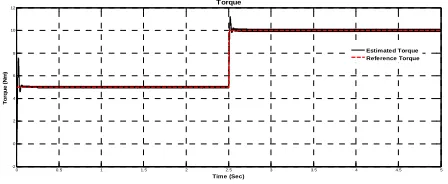
Simulation result of the electromagnetic torque is shown in figure 4 which proved that the torque
ripples got reduced in case of SVM based DTC.
0 0.5 1 1.5 2 2.5 3 3.5 4 4.5 5
-2 0 2 4 6 8 10 12
Time (Sec)
T
o
rq
u
e
(
N
m
)
Torque
Estimated Torque Reference Torque
Figure 4 Simulation Results Of Electromagnetic Torque [87]
4. FUZZY LOGIC BASED DTC
Conventional DTC of IM drive has the limitations of constant duty ratio for every
switching period and high torque ripples. These problems are rectified using fuzzy logic control
technique as presented in [10], [11]. In [13], [15],
it is presented that the implementation of fuzzy logic and artificial neural network reduced the
stator flux and torque ripples.
In [14] Look-up Table based on-line
tuning PI controller is proposed for outer speed control loop to achieve swift response, less
overshoot and precision speed control to have wide torque-speed characteristics. A new
algorithm for optimized value of stator flux based
on the maximum reference value of electromagnetic torque is proposed to operate in
conjunction with duty ratio control.
Figure 5 Schematic Diagram Of Proposed DTC With Fuzzy Logic Duty Ratio Controller [14]
Figure 5 shows the proposed DTC with duty ratio controller. To make the torque and
duty ratio variations smaller, the universe of
discourse of torque error and duty ratio are divided into five overlapping fuzzy sets. However,
to reduce the complexity of design, the stator flux position is defined with three overlapping fuzzy
sets only. The universe of discourse of all the variables, covering the whole region is expressed
in per unit values. The fuzzy subsets are defined with triangular membership functions as shown in
Figure 6. The linguistic labels are defined as VS =
Very Small, S = Small, M = Medium and L = Large, VL – Very Large.
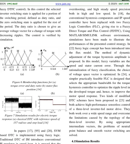
The simulation results shown in figure 7 clearly depict the superiority of devised
method over the existing methods of DTC. In [16] the stator flux is compensated using fuzzy logic,
the selection of the most suitable duty cycle value for every switching period is done, so the
switching frequency of the inverter is maintained
as constant. Hence the torque ripple is reduced. In [94] control of an IM using the principle of direct
torque and flux control (DTFC) is proposed. This method is designed by means of fuzzy logic with
three inputs and three outputs and contains 180 rules. For improvement of this method a fuzzy
duty ratio controller is added. This controller
[image:9.612.93.317.343.435.2]ISSN: 1992-8645 www.jatit.org E-ISSN: 1817-3195 fuzzy DTFC control). In this control the selected
inverter switching state is applied for a portion of
the switching period, defined as duty ratio, and the zero switching state is applied for the rest of
the period. The duty ratio is chosen to give an
average voltage vector for a change of torque with decreasing ripples. The control is verified by
simulation.
[image:10.612.91.522.69.546.2](a) (b)
Figure 6 Membership functions for (a) torque error and duty ratio (b) stator flux
position [14]
(a) (b)
Figure 7 Simulation results for electric torque response (a) classical DTC with reference speed of
157 rad/sec and step load [14]
In papers [17], [95] and [20], SVM based DTC is implemented using fuzzy logic.
Traditional DTC of IM introduces conventional PI regulator in speed loop, it is proved that the
low precision of the speed regulator debases the
performance of the whole system. In [12] and [19] a fuzzy speed PI regulator was established,
which applies the principles and method of fuzzy logic to adjust the proportional coefficient kp and
integral coefficient kI of the PI regulator on-line,
and finally get the system to adapt to different
speed variations. The proposed method is implemented with a single board microcomputer
that uses TMS320LF2407A DSP. The
experimental results showed that the fuzzy speed regulator can ensure swift speed response, small
overshooting, and high steady speed precision both in high and low speed. In [18], the
conventional hysteresis comparators and IP speed controller have been replaced with two Fuzzy
Logic Controllers (FLC), giving rise to a Fuzzy
Direct Torque and Flux Control (FDTFC), Using MATLAB/SIMULINK software environment,
simulations have been made to illustrate the performances of the presented control strategy. In
[22] fuzzy logic concept has been introduced into the flux model. The method of dynamic
adjustment of the torque hysteresis amplitude is proposed. In this model, fuzzy variables are the
speed and stator current error. Through the
rationalization of fuzzy classification, the choice of voltage space vector is optimized. In [24], a
simpler practically feasible FLC is designed that selects the appropriate bandwidth for the torque
hysteresis controller to optimize the ripple level in the developed torque and, hence, to improve the
motor speed response. Two kinds of modified DTC schemes have been proposed in [23] and
both achieve high-performance sensorless control
of a three-level inverter-fed motor drive. They both work over a wide speed range and overcome
the limitations caused by the topology of the three-level inverter. By using appropriate
intermediate vectors, the problems of neutral point balance and smooth vector switching are
solved.
4.1Simulation Results
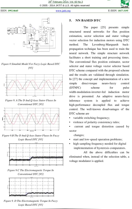
Figure 8 shows the proposed fuzzy logic based DTC [95]. The model includes
subsystems for flux and torque calculations and switching vector determinations. Interesting
results are shown in figure 9. As shown in figure
9 the flux and torque pulsations are smaller in the proposed fuzzy logic based DTC compared with
ISSN: 1992-8645 www.jatit.org E-ISSN: 1817-3195
Figure 8 Simulink Model For Fuzzy Logic Based DTC [95]
Figure 9. A The D And Q Axes Stator Fluxes In Conventional DTC [95]
Figure 9.B The D And Q Axes Stator Fluxes In Fuzzy Logic Based DTC [95]
0.1 0.15 0.2 0.25 0.3 0.35 0.4 0.45 0.5
-50 0 50 100 150 200
Time in secs
T
O
R
Q
U
E
i
n
N
m
TORQUE
Figure 9.C The Electromagnetic Torque In Conventional DTC [95]
0.1 0.15 0.2 0.25 0.3 0.35 0.4 0.45 0.5
0 50 100 150 200 250
Time in secs
T
O
R
Q
U
E i
n
N
m
TORQUE
Figure 9. D The Electromagnetic Torque In Fuzzy Logic Based DTC [95]
5. NN BASED DTC
The paper [25] presents simple
structured neural networks for flux position estimation, sector selection and stator voltage
vector selection for induction motors using DTC method. The Levenberg-Marquardt back-
propagation technique has been used to train the neural network. The simple structure network
facilitates a short training and processing times.
The conventional flux position estimator, sector selector and stator voltage vector selector based
DTC scheme compared with the proposed scheme and the results are validated through simulation.
In [27] the concept and implementation of a new simple direct-torque neuro-fuzzy control
(DTNFC) scheme for pulse
width-modulation-inverter-fed induction motor
drive is presented. An adaptive neuro-fuzzy
inference system is applied to achieve high-performance decoupled flux and torque
control. The well-known disadvantages of' the DTC scheme are
• variable switching frequency;
• violence of polarity consistency rules; • current and torque distortion caused by
sector changes;
• start and low-speed operation problems; • high sampling frequency needed for digital
implementation of hysteresis comparators. All the above difficulties can be
eliminated when, instead of the selection table, a
ISSN: 1992-8645 www.jatit.org E-ISSN: 1817-3195
Figure 10 Proposed Scheme With Neuro-Fuzzy Controller And Voltage Modulator [27]
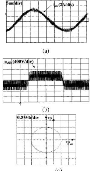
In this paper, a new controller based on an adaptive NF inference system (ANFIS) for
voltage space-vector generation is proposed. This
controller combines fuzzy logic and artificial neural networks for decoupled flux and torque
control. Figure 10 shows the proposed NF controller with voltage modulator and figure 11
shows two input NF controller. Figure 12 shows the experimental results.
The presented DTNFC scheme has the following features and advantages:
• only one controller; • simple tuning procedure;
• constant switching frequency and unipolar motor voltage
• torque and current harmonics mainly dependent on sampling time;
• no current and torque distortion caused by sector changes (there are no sectors borders);
• fast torque and flux response; • no problems during low-speed
operation:
• lower sampling time; • possible online tuning;
In [28] apart from six sector look up table used for classical DTC, a modified look up
table, which also use six sectors but with different zones and a twelve sector table are presented.
This paper also presents the application of neural
[image:12.612.97.553.68.234.2]networks to control induction machines with DTC.
Figure 11 Two-input NF controller structure [27]
NN is used to emulate the state selector of the DTC. In this paper Levenberg-Marquardt algorithm is used to train the neural network. In [26] author first model the DTC of Inv-IM as a hybrid system (HS). Then, they abstract the continuous dynamics of the HS in terms of discrete events to obtain a discrete event model of the HS.
(a)
(b)
(c)
Figure 12 Experimental results for the steady state-operation for the tuned DTNFC system;
[image:12.612.345.494.382.665.2]ISSN: 1992-8645 www.jatit.org E-ISSN: 1817-3195
6. FPGA BASED DTC
Modern AC drives require a fast digital realization of many mathematical
operations concerning control and estimator's algorithms, which are time consuming. Therefore
developing of custom-built digital interfaces as
well as digital data processing blocks and sometimes even integration of ADC converters
into single integrated circuit is necessary. Due to the fact that developing an ASIC chip is
expensive and laborious, the FPGA based solution should be used on the design stage of the
algorithm. In [36], the application of FPGA in DTC of IM drive is presented. In [30], the DTC
was implemented in FPGA using fixed point
arithmetic with a variable word-size approach. This is proposed as an alternative to 16 or 32-bit
choices used before. A separation of the algorithm in functional blocks is used to simplify validation
task which was accomplished in comparison with MATLAB results. Following a tendency in the
research area, the algorithm proposed is implemented in unique FPGA device, which
allows for a faster validation and simplifies the
control structure. To ensure a proper voltage vector selection by the DTC controller, the
estimation of stator flux must be accurate. The calculation of the electromagnetic torque too,
depends on the accuracy of stator flux estimation. Most of the stator flux calculation is based on
voltage model, current model or the combination
of both models. These models require a precise
calculation to accurately estimate the flux. In [33], an arithmetic approach of
DTC strategy using complex number and floating point representation is implemented using FPGA.
The motor / inverter dynamics is executed in
Matlab / Simulink. The Xilinx software performs the speed control and the DTC procedure which is
written in VHDL (Very high speed integrated circuit hardware Description Language).
Simulation results of this high performance drive system on 1/4 hp standard induction motor are as
expected and agree with the theoretical work. This work shows the simulation of the DTC
control technique using Matlab / Simulink with
Xilinx/ ModelSim program simultaneously, allowing a global co-simulation of the motor
dynamics and the DTC strategy coded in VHDL. The inverter drive and the induction motor were
implemented in a Matlab/ Simulink environment as in figure 13. The DTC control strategy was
implemented in VHDL language using Xilinx program. DTC strategy was executed exclusively
in VHDL, using complex number calculation with
floating point representation. For a fixed point representation all the quantities (data and
constants) are represented by integers in a fixed range. This means that each must be converted to
fit within this range. This must be done without decreasing accuracy. Complex number and
floating point representation in DTC scheme gives higher computational accuracy than the
ISSN: 1992-8645 www.jatit.org E-ISSN: 1817-3195
Figure 13 Matlab/Simulink diagram representation of the DTC induction motor drive system [33]
In this representation, all the variables and every
mathematical operation are directly described. The use of complex number calculation with
floating point representation is new proposal of this work with regard to similar study.
The paper [31] introduces a new
digital logic design, which combines the DSP and FPGA to implement the conventional DTC of
induction machine. The DSP will be used for floating point calculation whereas the FPGA main
task is to implement the hysteresis-based controller. The emphasis is on FPGA digital logic
design. The simulation and experimental results
are presented and summarized. The paper [40] presents a simple approach to design and
implementation of DTC of three phase squirrel cage induction motor using Matlab/Simulink and
FPGA software. To maintain the simplicity of DTC while at the same time improving the
performance two simple new techniques i.e. constant switching frequency and stator flux
estimation are proposed. To maintain a constant
switching a simple torque control is introduced to replace the three level hysteresis comparators.
The magnitude and phase error associated with stator flux estimation based on voltage model is compensated by using simple compensator which is based on steady state
operation. In [29] the author proposed a pair of torque and flux controllers to replace the hysteresis based controllers as in figure 14. The design of these controllers is fully discussed and a set of numerical values of the parameters for the proposed controllers is given. The simulation of the proposed controllers applied to the DTC drive is presented and simulation results are then verified by experimental results.
Figure 14 Implementation of proposed controllers using DSP and FPGA [29]
[image:14.612.334.522.479.611.2]ISSN: 1992-8645 www.jatit.org E-ISSN: 1817-3195 the switching frequency is fixed at 10.4 kHz and a
more sinusoidal phase current is obtained. The paper [34] describes a combination of DTC and SVM for an adjustable speed sensorless IM drive. The motor drive is supplied by a two level FPGA-based SVPWM inverter. The inverter reference voltage is obtained based on input-output feedback linearization control, using the IM model in the stator d-q axes reference frame with stator current and flux vectors components as state variables. In addition, a conventional PI speed controller is employed to generate the reference torque signal. Moreover, a novel Lyapunov based nonlinear stator flux observer is developed which provides simultaneous estimation of the stator flux, rotor speed, and rotor and stator resistances. Finally, the effectiveness and validity of the proposed control approach is verified by computer
simulation and experimental results. In [39], [38] and [35] the FPGA is
applied to the whole speed sensorless DTC
control structure. This application contains decomposed DTC and the speed observer
algorithms, with the supervised speed controller. The DTC algorithm was decomposed as follows:
-
- data acquisition,
- algebraic coordinate transformations of measured stator phase currents and calculated
stator voltages from phase variables ABC to
stationary reference frame values α-β
- estimation of the stator flux vector
coordinates.
- electromagnetic torque estimation,
- determination of the stator flux's amplitude and position (using CORDIC) for the sector N
determination, - sector determination,
- comparators' states determination,
-determination of the appropriate set of the
inverters switch on states.
The observer algorithm was decomposed into
the following tasks:
- estimation of the stator current coordinate in α axis,
-estimation of the stator current coordinate in β axis,
- estimation of the rotor flux coordinate in α axis.
- estimation of the rotor flux coordinate in β axis.
- adaptation mechanism and speed estimation. The stator flux coordinates ψsα, ψsβ,
are transformed to polar coordinates (ψs, γs),
using the CORDIC scheme. Few issues concerning the implementation of IM drive
control structures in FPGA are discussed. The use of CORDIC algorithm for some mathematical
operations in the DTC method is described. Experimental test results of this drive control
structure realized in FPGA are demonstrated. The example of the sinusoidal signals transients and
their magnitude as well as rotation angle,
determined using the CORDIC algorithm are presented in the figure15a, while the calculated
stator and rotor flux hodographs are shown in figure 15b, c.
Simulations are carried out when System Generator (SG) toolbox working in the
MATLAB/ SIMULINK environment. The results are presented and discussed to evaluate the DTC
operating under considered faults.
ISSN: 1992-8645 www.jatit.org E-ISSN: 1817-3195
Figure 15 An Example Of The Sinusoidal Signal Magnitude And Angle Transients, Determined Using CORDIC In Translation Mode (A) Holographs Of The Stator (B) And Rotor (C) Fluxes [35]
The results are presented and discussed to
evaluate the DTC operating under considered faults.
In [37], authors present a FPGA-based implementation of Direct Torque
and Stator Flux Control (DTSFC) and Direct Torque and Rotor Flux Control (DTRFC) with
and without use of SVM for induction motor
drives. Indeed, due to their similar structures but also their differences, this set of algorithms is a
good example to show the effectiveness of a FPGA-based modular approach to implement
sensorless control induction motor drives. Therefore, the chosen solution is based on a
custom hardware architecture designed by assembling a set of building blocks. These blocks
are tested and organized in a library of Intellectual
Property (IP) modules for easy re-use. Each block is geared toward specific algorithm function (Flux
estimator, Hysteresis controller... ). Besides, a special attention is given to the algorithm
refinement which allows finding the optimum fixed-point data word length. Finally
experimental results are shown which validate the
proposed approach. In [32] a
microcomputer-based direct primary flux and
torque control system for the three-phase induction motor is presented, showing that the
instantaneous primary flux of the induction motor can be calculated by means of computer software.
The control algorithm can be implemented on line with an 1 K-ROM memory. The controller,
therefore, can be quite compact, and both the
hardware and software implementations are easy
to achieve. A full digital controller with a 16-b microcomputer is developed. The experimental
results are presented and agree with the theory. Efficiency optimization of IM drives
is a major subject based on these drives extensive use in the industry. Among the different proposed
methods, a model based approach (MBA) seems
to be the fast one [41]. However, this method needs the motor parameters that must be correctly
identified. On the other hand, a search-based approach (SBA) is a parameter-independent
method but needs a greater convergence time. In this paper, a novel model-based loss-minimization
approach is presented, which is combined with a back stepping DTC of the IM drive. An improved
search-based method for efficiency optimization
is also introduced. The proposed controller is realized in the stationary reference frame and has
a fast-tracking capability of rotor flux and electromagnetic torque. Moreover, a sliding-mode
rotor-flux observer is introduced, which is employed for simultaneous determination of
rotor-flux space vector, rotor speed and rotor time constant. The proposed control idea is
experimentally implemented in real time using a
FPGA board synchronized with a personal computer. Simulation and experimental results are
finally presented to verify the effectiveness of the method proposed.
6.1Simulation Results
ISSN: 1992-8645 www.jatit.org E-ISSN: 1817-3195 and simulated using ModelSim 6.3 and the
simulation results are shown in figure 16.
Figure 16. Simulation results showing the sector selection S2 for an angle 79.5 (60 > α > 120)
The simulation result also showed the three phase
(abc) to two phase (dq) transformation, stator flux and torque estimations and proper sector
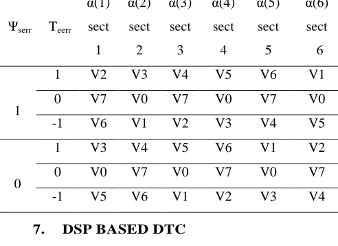
[image:17.612.66.312.417.596.2]selections from table 4 based on SVM technique.
Table 4 Switching Table of Inverter Voltage Vectors
Ψserr Teerr
α(1)
sect
1
α(2)
sect
2
α(3)
sect
3
α(4)
sect
4
α(5)
sect
5
α(6)
sect
6
1
1 V2 V3 V4 V5 V6 V1
0 V7 V0 V7 V0 V7 V0
-1 V6 V1 V2 V3 V4 V5
0
1 V3 V4 V5 V6 V1 V2
0 V0 V7 V0 V7 V0 V7
-1 V5 V6 V1 V2 V3 V4
7. DSP BASED DTC
In [45] two different strategies (1) Conventional DTC and (2) Space vector PWM based DTC are tested and implemented. The entire simulation is performed in real time using TMS320LF2407 digital signal processor. The dynamic machine model with 5 state variables is solved in real time in order to determine the state variables and hence various output quantities. Using the same controller and software used in HIL simulation and with additional signal
conditioning interface circuitry, the results obtained from real time simulation are experimentally validated on a 1.5-kW induction motor drive. A new tool known as “automatic code generation" is introduced, which is capable of generating assembly language code for real time simulation of electric drives. The results of real time simulation and those obtained from a laboratory prototype are presented.
ISSN: 1992-8645 www.jatit.org E-ISSN: 1817-3195 control of the torque and flux with constant
[image:18.612.97.285.215.371.2]inverter switching frequency and a minimum torque and flux ripple. Compared to the other DTC methods, this algorithm is much simpler and has less mathematical operations, and can be implemented on most existing digital drive controllers.
Figure 17 Experimental Setup Of The Proposed Method [47]
Algorithm is based on imposing the flux vector spatial orientation and rotation speed, which defines the unique solution for reference stator voltage. The implementation of the control scheme using DSP – based hardware is described, with complete experimental evidence and the straightforward implementation instructions.
The paper [47] proposed a simple but
effective method to reduce the torque ripple for DTC of IM drives. The proposed DTC provides a
global minimum torque ripple, which satisfies the root-mean-square (rms) criteria of torque ripple.
Such a global minimum torque ripple DTC has not been derived before. The proposed global
minimum torque ripple DTC is a two-step design.
The first step drives the torque error to zero at the end of the control period. Then, the second step
reduces the torque bias and rms ripple by modifying the asymmetry switching patterns of
the applied voltage vectors of the first step into symmetry ones. Theoretical analysis is provided
to show that the torque ripple of the proposed DTC is a global minimum rms ripple.
Furthermore, to verify the effectiveness of this
study, a DSP-based experimental induction motor DTC drive system is built and shown in figure17
and figure 18. In [44] a novel scheme for the direct torque control (DTC) of an induction motor
(IM) is proposed, which uses a single sensor of current inserted in the inverter dc link. The
rationale behind the proposal is to develop a low-cost but high performance IM drive. The
scheme exploits a simple and robust algorithm to
reconstruct the stator currents needed to estimate the motor flux and torque.
The algorithm operates in two stages: first, it predicts the stator currents from a model
of the motor and then adjusts the prediction on the basis of the sensed dc-link current. Experimental
results are given to demonstrate the ability of the scheme in reproducing the performance of a
traditional DTC IM drive.
[image:18.612.97.538.561.686.2]ISSN: 1992-8645 www.jatit.org E-ISSN: 1817-3195
8. CONCLUSION
This paper reviewed the origin and development of advanced control technique called direct torque control and its superior performance on induction motor drive. First the basic principle of DTC and FOC are carefully reviewed and compared. Then the problems associated with DTC and the proposed solutions are reviewed. Certain modifications on DTC to get improved performance are also discussed.
Further, implementation of intelligent control techniques such as fuzzy logic and neural networks on DTC are reviewed and the improvements are systematically analyzed. It has been concluded that the implementation of intelligent techniques reduced the stator flux and torque ripples and therefore the dynamic performance of the drives are improved. Then the implementation of DTC using FPGA is reviewed and results are discussed. It has been proved that hardware realization can be done easily using FPGA, but there exists a problem in estimating stator flux accurately due to fixed point representation. This problem could be solved if the algorithm is implemented using digital signal processors as presented.
REFERENCES
[1] Nalin Kant Mohanty, Ranganath Muthu and M.Senthil Kumaran, “A survey on controlled AC electrical drives”,
International Journal of Electrical and
Power Engineering, 3(3), 2009,
pp.175-183.
[2] R.Krishnan, “Electric Motor Drives –
Modeling, Analysis, and Control”,
Prentice Hall of India, 2002.
[3] B.K.Bose, “Modern Power Electronics and
AC Drives”, Prentice – Hall, New Jersey,
2002.
[4] P.Vas, “Sensorless Vector and Direct Torque Control”, Oxford University Press, New York, 1998.
[5] T.Noguchi and I. Takahashi, “Quick torque response control of an induction motor based on a new concept” (in Japanese), IEEJ Tech. Meeting Rotating Mach.,
Vol. RM 84–76, Sept. 1984, pp. 61–70.
[6] Isao Takahashi, Toshihiko Noguchi, “A new quick response and high efficiency control strategy of an induction motor”, IEEE Transactions on Industry
Applications, Vol.1A-22, No.5,
Sep/Oct.1986, pp.820 – 827.
[7] Isao Takahashi, Youichi Ohmori, “High performance direct torque control of an induction motor”, IEEE Transactions on
Industry Applications, Vol.25, No.2,
March/April 1989, pp.257-264. [8] Domenico Casadei, Franusco Profumo,
Giovanni Serra, and Angelo Tani, “FOC and DTC: Two viable schemes for induction motors torque control”, IEEE Transactions
on Power Electronics, Vol.17,
No.5, Sep.2002, pp.779 – 787.
[9] “Direct torque control — The world’s most advanced AC drive technology,” ABB Finland, Helsinki, Tech. Guide 1, 1996. [10] Rintu Khanne, Manisha Sinla and Gurpreet
Kaur, “Fuzzy logic based direct torque control of induction motor”, IEEE, 2009, pp.1-5.
[11] Fatina Zidani, Rachid Nait Sais, “Direct torque control of induction motor with fuzzy minimization torque ripple”, Journal of Electrical Engineering, Vol.56, No.7-8, 2005,
pp.183 -188.
[12] JIA – Qiang Yang, Jin Huang, “Direct torque control system for induction motors with fuzzy speed PI Regulator”,
Procedings of the fourth International
Conference on Macinne Learning and
Cybernetics, Guanghlou, 18-21, August
2005, pp.778 – 783.
[13] R.Toufouti S.Meziane, H.Benalla, “Direct torque control for induction motor using intelligent techniques”, Journal of
theoretical and Applied Information
Technology, 2007, pp.35-44.
[14] Y. Srinivasa Kishore Babu and G. Tulasi Ram Das, “Improvement in direct torque control of induction motor using fuzzy logic duty ratio controller”, ARPN Journal of
Engineering and Applied Sciences,
Vol.5, No.4, April 2010, pp.68-74.
[15] Soufien Gdaim, Abdellatif Mtibaa, Mohamed Faouzi Mimouni, “Direct torque control of induction machine based on intelligent Techniques”, International Journal
of Computer Applications
(0975 - 8887), Vol.10, No.8, Nov. 2010, pp.29-35.
[16] K.Ramani, A.Krishnan, “Simulation based direct torque control of induction motor with stator flux reimbursement”,
ISSN: 1992-8645 www.jatit.org E-ISSN: 1817-3195
Engineering, Vol.2, No.6, Nov.2009,
pp.10-12.
[17] Yuedou Pan, Yihai Zhang, Zhe Wang, “A novel variable domain adaptive fuzzy control of direct torque control for induction motor based on space vector control”, Seventh International
Conference on Fuzzy Systems and
Knowledge Discovery (FSKD 2010),
2010, pp.639-643.
[18] A.Lokriti, Y.Zidani, S.Doubabi, “Fuzzy logic control contribution to the direct torque and flux control of an induction machine”, IEEE 2010.
[19] Deng Jinlian and Tu Li, “Improvement of direct torque control low speed performance by using fuzzy logic technique”, Proceedings of the 2006 IEEE International Conference on Mechatronics and Automation, China, June 25-28, 2006, pp.2481-2485.
[20] Jagadish H.Pujar, S.F.Kodad, “AI based direct torque fuzzy control of AC drives”,
International Journal of Electronic
Engineering Research, Vol.1, No.3,
2009, pp.233-244.
[21] Sarat Kumar Sahoo, G.Tulasi Ram Das and Vedam Subrahmanyam, “Sensor fault tolerant of direct torque control in induction motor drives”, International Journal
of Recent Trends in
Engineering, Vol.2, No.6, Nov.2009,
pp.44-49.
[22] Gao Sheng – Wei, Cai Yan, “Research on torque ripple minimization strategy for direct torque control of induction motors”, International Conference on
Computer Applications and System
Modeling (ICCASM 2010),
pp.V6-278-281.
[23] Yongchang Zhang, Jianguo Zhu, Zhengming Zhao, Wei Xu, and David G.Dorrell, “An improved direct torque control for three-level inverter – fed induction motor sensorless drive”, IEEE Transactions on
Power Electronics, Vol.27, No.3,
March 2012.
[24] M.Nasir Uddin, Muhammaed Hafeez,”FLC – based DTC scheme to improve the dynamic performance of an IM drive”, IEEE Transactions on industry
applications, vol.48, No.2, March/April
2012.
[25] Rajesh Kumar, R.A.Gupta, S.V.Bhangale, Himanshu Gothwal, “Artificial neural
network based direct torque control of induction motor drives”, IETECH Journal of
Electrical Analysis, Vol.2, No.3,
pp.159-165, 2008.
[26] Hamid Yantour, Janah Saadi, Ahmed Khoumsi, “A hybrid system based approach to direct torque control (DTC) of induction motors”,
18th Mediterranean Conference on
Control and Automation, Morocco,
pp.327-332, June 23-25, 2010.
[27] Pawel Z.Grabowski, Marian P.Kazmierkowski, Bimal K. Bose, and Frede Blaabjerg, “A simple direct – torque Neuro – Fuzzy control of PWM – inverter fed induction motor drive”, IEEE Transactions on Industrial Electronics, Vol.47, No.4, Aug.2000, pp.863 – 870.
[28] Y.V.Siva Reddy, M.Vijayakumar and T.Brahmananda Reddy, “Direct torque control of induction motor using sophisticated look up tables based on Neural networks”, AIML Journal, Vol.7, June 2007, pp.9-15.
[29] Nik Rumzi Nik Idris, Chuen Ling Toh, and Malik E. Elbuluk, “A new torque and flux controller for direct torque control of induction machines”, IEEE Transactions on
Industry Applications, Vol.42, No.6,
Nov/Dec 2006, pp.1358-1366.
[30] Sandro Ferreira, Felipe Haffner, Luis Fernando Pereira, Fernando Moraes, “Design and prototyping of direct
torque control of induction motors in FPGAs”, Proceedings of the 16th
Symposium on Integrated Circuits and
Systems Design (SBCCI), 2003.
[31] C.L.Toh, N.R.N.Idris, A.H.M.Yatim, “Design and implementation of TMS320C31 DSP and FPGA for conventional direct torque control (DTC) of induction machines”,
World Academy of Science, Engineering and Technology, 2009, pp.448-453.
[32] Hao Yun Zhong, Henry P. Messinger,
Muhammad H.Rashid, “A new
microcomputer based direct torque control system for three phase induction motor”, IEEE Transactions on industry Applications, Vol.27, No.2, March/April
1991, pp.294-298.
[33] Sarat Kumar Sahoo, G.Tulasi Ram Das,
Vedam Subrahmanyam, “VLSI
design approach to high performance direct torque control of induction motor

![Figure 14 Implementation of proposed controllers using DSP and FPGA [29]](https://thumb-us.123doks.com/thumbv2/123dok_us/8913726.960650/14.612.96.535.68.294/figure-implementation-proposed-controllers-using-dsp-fpga.webp)
![Figure 15 An Example Of The Sinusoidal Signal Magnitude And Angle Transients, Determined Using CORDIC In Translation Mode (A) Holographs Of The Stator (B) And Rotor (C) Fluxes [35]](https://thumb-us.123doks.com/thumbv2/123dok_us/8913726.960650/16.612.95.521.70.205/figure-example-sinusoidal-magnitude-transients-determined-translation-holographs.webp)