© 2017, IRJET | Impact Factor value: 6.171 | ISO 9001:2008 Certified Journal | Page 358
Analysis and Design of an Earthquake Resistant Structure using
STADD. Pro
Akshay R. Kohli
1, Prof. N. G. Gore
21B.E. Undergraduate, 2Assistant Professor, Dept. of Civil Engineering. 1,2 MGM’s College of Engineering & Technology, Navi Mumbai, Maharashtra, India.
---***---Abstract
- With the advent of advanced technology, civilstructures such as high-rise buildings and long span bridges are designed with increased flexibility, increasing their susceptibility to external excitation. Therefore, these structures are vulnerable to excessive modes of vibration under the effect of a strong wind and earthquake. To protect such civil structures from significant structural damage, the seismic response of these structures is analyzed along with wind force calculation and forces such as support reactions and joint displacement are calculated and included in the structural design for a vibration resistant structure. The primary objective of this paper is to create an earthquake resistant structure by undertaking seismic study of the structure by static equivalent method of analysis and carry out the analysis and design of the building using STADD. Pro software. For this purpose, a G+11 residential building plan in Mumbai is considered. Seismic calculations are conducted for earthquake zone 3, Response reduction factor 3, for ordinary moment resistant frame and Importance factor 1. The structural safety of the building is ensured by calculating all acting loads on the structure, including the lateral loads caused due to wind and seismic excitation.
Key Words: STADD. Pro, analysis, seismic force, ordinary moment resisting frame, fundamental period, inter-story drift, equivalent static analysis, IS code.
1. INTRODUCTION
Structural design is the science of analyzing and designing any structure with ultimate strength, safety, serviceability and economy. It not only requires conceptual thinking and imagination but also the discipline to maintain design standards specified by the respective country design code, for example IS Code. Any building project initiates from the planning stage to meet the specified requirement of the client. Although the client may be unaware of the impracticable conditions existing within the site and have unprecedented expectations, it is the sole responsibility of the structural engineer to undertake
The challenge and meet the design requirements for strength, durability, economy and safety.
The existing shortage of land due to the human population out-burst is constantly demanding the construction of high-rise structures. As the floor count of these multi-story
buildings increase, the structure gets vulnerable to external lateral forces subjected by earthquake excitation and wind pressure, thus leading to structural instability and subsequently complete failure of the structure. To enable tall structures resistant to such lateral forces, analysis of the forces due to earthquake and wind must be undertaken and included in the ultimate design of the building.
1.1 Stages in Structural Design
Every structure follows a specific path from its initiation to ultimate design as follows:
Calculation of applied loads.
Structural analysis of the building
Design of the building as per analysis.
Drawing and detailing of the structural members.
Preparation of schedule.
It is the sole responsibility of the design engineer to construct the building structurally sound, considering all the loads acting on the building. There are multiple methods of conducting these design procedures, one of which is the use of STADD. Pro software.
1.2 Introduction to STADD. Pro
STADD. Pro provides the design engineer with excellent user interface and tools required to impose dead load and imposed load along with external acting loads on the structure. It has a powerful engine to undergo advanced
dynamic analysis considering multiple loading
combinations and generate an appropriate design of the structure. The software gives easy access to view reaction forces, joint displacement, shear force and bending moment acting on different beams and columns in the post-processing mode due to the applied loading condition on the structure.
STADD. Pro provides a vast interface to carry out timber, aluminum and concrete design of building, bridge and water tank. From model generation to ultimate design, the software provides accurate results and submits the final output which contains the structural design of every individual beam and column within the building.
International Research Journal of Engineering and Technology (IRJET)
e-ISSN: 2395-0056 Volume: 04 Issue: 12 | Dec-2017 www.irjet.net p-ISSN: 2395-0072© 2017, IRJET | Impact Factor value: 6.171 | ISO 9001:2008 Certified Journal | Page 359 1.3 Getting Started
This paper contains detailed information on the methodology to analyze and design a structure on STADD. Pro from model generation, fixation of supports, load analysis and finally building design. Step by step procedure has been explained with the help of diagrams. Further, load calculations have been explained in depth and manual seismic and wind calculations have also been undertaken.
2. OBJECTIVES
The primary objective of this paper is to undergo lateral load analysis and design an earthquake resistant structure on STADD. Pro. The objectives have been specified as follows:
Generation of building model on STADD. Pro.
Load calculation due to different loading
conditions.
Application of loads on STADD. Pro model.
Analysis of the structure on STAD. Pro.
Study of the reaction forces, shear force, bending
moment and node displacement.
Design of the building.
3. METHODOLOGY TO UNDERTAKE ANALYSIS AND DESIGN OF G+11 BUILDING ON STADD. PRO
Step-1: Nodal point generation.
With respect to the positioning of the column on the building plan we, respective nodal points have been entered on the STADD model.
Step-2: Beam and column representation.
Based on the nodal points, with the help of add beam command on STADD. Pro, beam and columns have been generated.
Step-3: Assign support and member property.
After column generation, supports have been provided below every column as fixed supports.
Subsequently, based on load calculations, the beam and column cross-sections have been assigned.
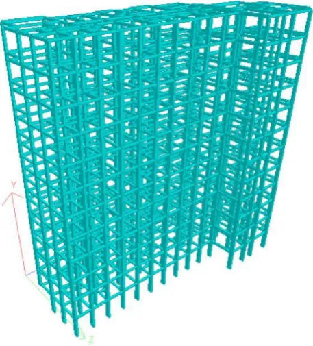
Step-4: 3D View.
After assigning the member property, the 3D view of the structure can be shown.
Step-5: Dead Load assignment.
According IS: 875 (Part 1) – 1987, the dead loads have been assigned based on member load, floor load and self-weight of the beams.
Step-6: Live Load assignment.
According to IS: 875 (Part 2) – 1987, live load of 2KN/m2
has been assigned to the members.
Step-7: Seismic load assignment.
After creating suitable seismic definition as per the
requirement of IS 1893 (Part 1) : 2002, the seismic load
has been assigned with respect to +X, -X, +Z and -Z directions with appropriate seismic factor.
Step-8: Wind load assignment.
After entering the wind intensity and creating the wind
definition as perIS: 875 (Part 3) – 1987, the wind loads
have been assigned with respect to +X, -X, +Z and -Z directions.
Step-9: Load combination assignment.
Different load combination cases have been assigned to the model based on specified loading combinations provided in the IS CODES that are also available in STADD. Pro.
Step-10: Analysis of the structure on STADD. Pro.
With the help of the Run Analysis Command, the structure is analyzed and detailed study of forces and bending moment is undertaken through the Postprocessing mode.
Step-11: Structural Design on STADD. Pro and Output Generation.
The design is undertaken as per IS 456:2000. M25 concrete and FE415 is used as design parameters. Percentage steel of 4% has been specified as per IS Code standards and the design parameters have been assigned to respective beam and column. After the final design of the structure, the output file is generated containing the structural design of every individual beam and column member.
4. ANALYSIS OF G+11 BUILDING
© 2017, IRJET | Impact Factor value: 6.171 | ISO 9001:2008 Certified Journal | Page 360
Fig – 1: Seismic zoning map of India
4.1 Response Spectrum
The response spectrum coefficient considered as per Indian Standards for design, is shown in the figure for different soil type based on suitable natural periods and damping ratio of the structure. The spectral acceleration coefficient (Sa/g) considered as per IS 1893 (Part 1): 2002 is as follows.
Fig – 2: Response spectra for 5% damping
[image:3.595.42.282.80.331.2]The response reduction factor for different building systems is considered as per the table below.
Fig – 3: Response reduction factor
The building is designed as an ordinary moment resisting frame (OMRC) for the considered residential structure without ductile detailing and hence a response reduction factor of 3 is considered.
4.2 Project Statement
The building is designed for the following parameters:
Site location: Mumbai in Seismic Zone – III
Type of the soil: Medium soil.
Allowable bearing pressure: 150KN/m2
Response Reduction factor(R) – 3 for OMRC.
Number of Floors: 11
Floor Height: 3.3m
External thickness of wall: 230mm
Internal thickness of wall: 150mm
Beam Size: - 230x250 mm
[image:3.595.51.273.476.650.2]International Research Journal of Engineering and Technology (IRJET)
e-ISSN: 2395-0056 Volume: 04 Issue: 12 | Dec-2017 www.irjet.net p-ISSN: 2395-0072© 2017, IRJET | Impact Factor value: 6.171 | ISO 9001:2008 Certified Journal | Page 361
Column Size: - 230x400 mm
- 230x500 mm - 250x600 mm - 300x1000 mm (staircase).
Slab Thickness: 120
Live Load: 2KN/m2
Wind Load: IS: 875-(Part-3).
Earthquake Load: IS: 1893-2002(Part-1).
Grade of Concrete: M25
Grade of Steel: FE415
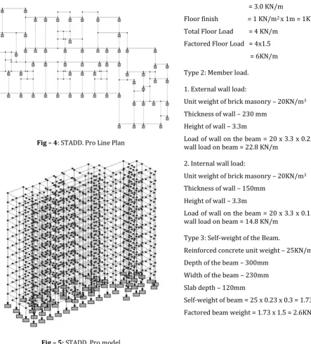
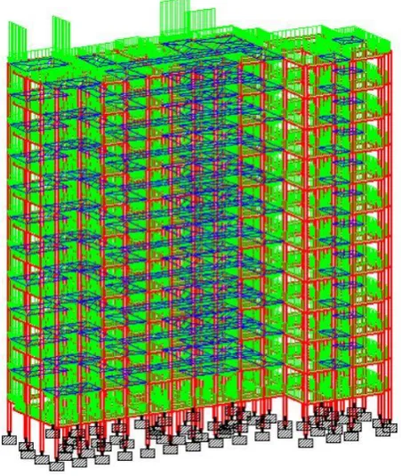
[image:4.595.46.490.270.760.2]The STADD. Pro plan and model for the considered G+11 building is shown below.
Fig – 4: STADD. Pro Line Plan
Fig – 5: STADD. Pro model
4.3 Load Calculation
Dead load, Live load, Seismic load and Wind load are calculated and entered into STADD. Pro model as give below.
4.3.1 Deal Load
Type 1: Floor load.
Reinforced concrete unit weight – 25KN/m3
Slab thickness -120mm
Deal load due to Slab = 25 x B X D = 25 x 1 x 0.12 = 3.0 KN/m
Floor finish = 1 KN/m2 x 1m = 1KN/m
Total Floor Load = 4 KN/m
Factored Floor Load = 4x1.5 = 6KN/m
Type 2: Member load.
1. External wall load:
Unit weight of brick masonry – 20KN/m3
Thickness of wall – 230 mm Height of wall – 3.3m
Load of wall on the beam = 20 x 3.3 x 0.23 x 1.5 Factored wall load on beam = 22.8 KN/m
2. Internal wall load:
Unit weight of brick masonry – 20KN/m3
Thickness of wall – 150mm Height of wall – 3.3m
Load of wall on the beam = 20 x 3.3 x 0.15 x 1.5 Factored wall load on beam = 14.8 KN/m
Type 3: Self-weight of the Beam.
Reinforced concrete unit weight – 25KN/m3
Depth of the beam – 300mm Width of the beam – 230mm Slab depth – 120mm
© 2017, IRJET | Impact Factor value: 6.171 | ISO 9001:2008 Certified Journal | Page 362
Fig – 6: Dead Load on STADD. Pro
4.3.2 Imposed Load (Live Load)
The load produced by the occupancy of the building, movable partition load, concentrated and distributed load, load due to vibration and impact, people occupying the floor but excluding all external loads caused by snow, wind and earthquake or temperature changes such as shrinkage, differential settlement, creep etc. is termed as imposed load.
The imposed loads have been considered in the design as per IS: 875 (Part 2) - 1987, clause 3.1, 3.1.1 and 4.1.1. Some of the values specified by the IS code have been mentioned below:
Residential Building UDL (KN/m2)
All rooms and kitchens 2
Toilet and bath rooms 2
Corridors, passage and staircase 3
[image:5.595.49.275.84.352.2]Balconies 3
Fig – 7: Live Load
4.3.3 Wind Load
The lateral forces acting on the structure due to wind have been calculated as per (IS: 875 (Part 3) – 1987).
Design Wind Speed VZ = VB K1 K2 K3 K4 (Section 5.3, IS: 875
(Part 3) – 1987).
Design Wind Pressure PZ = 0.6 x VZ2 (Section 5.4, IS: 875
(Part 3) – 1987).
Where,
PZ – Wind speed pressure (KN/m2).
VZ - Wind speed design (m/s).
VB – Basic Wind Speed at any height in m/s.
K1 - Probability factor.
K2 - Terrain roughness.
K3 - Topography Factor.
K4 – Importance factor in cyclonic region.
Exposure factor - 1.0 (As per IS Code).
For Mumbai,
Wind category - 4,
Wind Speed (VB) = 44m/s
K1 = 1 (Table 1, IS: 875 (Part 3) – 1987).
K2 = 1.04 (Table 2, IS: 875 (Part 3) – 1987).
K3 = 1 (Clause 5.3.3.1, IS: 875 (Part 3) – 1987).
K4 = 1 (Clause 5.3.4, IS: 875 (Part 3) – 1987).
With respect to the values of K1, K2, K3 and K4 listed above,
International Research Journal of Engineering and Technology (IRJET)
e-ISSN: 2395-0056 Volume: 04 Issue: 12 | Dec-2017 www.irjet.net p-ISSN: 2395-0072© 2017, IRJET | Impact Factor value: 6.171 | ISO 9001:2008 Certified Journal | Page 363 listed above. The square of the design wind speed is
multiplied by a factor of 0.6 and the value of design wind pressure is calculated. The below calculated wind pressure
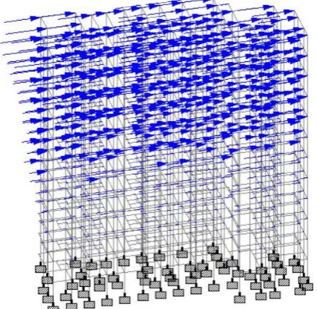
values (PZ) at each floor are provided as input to wind
[image:6.595.39.277.179.657.2]definition in STADD. Pro and the wind force acting on the structure is displayed below.
Table - 1: Lateral wind force
Height VB K1 K2 K3 K4 VZ PZ
39.6 44 1 1.03 1 1 45.32 1.23
36.3 44 1 1.01 1 1 44.44 1.18
33.0 44 1 0.99 1 1 43.56 1.14
29.7 44 1 0.97 1 1 42.68 1.09
26.4 44 1 0.91 1 1 40.04 0.96
23.1 44 1 0.85 1 1 37.40 0.84
19.8 44 1 0.8 1 1 35.2 0.74
16.5 44 1 0.8 1 1 35.2 0.74
13.2 44 1 0.8 1 1 35.2 0.74
9.9 44 1 0.8 1 1 35.2 0.74
6.6 44 1 0.8 1 1 35.2 0.74
3.3 44 1 0.8 1 1 35.2 0.74
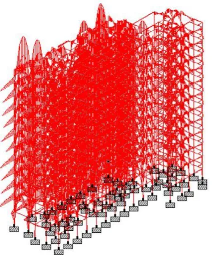
Fig – 8: Wind Force acting on STADD model
4.3.4 Seismic Load
To make the structure earthquake resistant, the fundamental period of the building while vibration should be calculated and provided as input to STADD. Pro for seismic analysis. The considered building is in Mumbai.
Seismic parameters as per (IS 1893 (Part 1) : 2002) are stated below:
Seismic Zone – III (IS 1893 (Part 1) : 2002)
Zone Factor (Z) – 0.16 (Table 2, IS 1893 (Part 1) : 2002) Importance factor – 1 (Table 6, IS 1893 (Part 1) : 2002) Response Reduction Factor – 3 (Table 7, IS 1893 (Part 1) : 2002)
Fundamental Period (Ta):
The formula for calculating the fundamental natural period of vibration for moment resisting framed building provided with brick infill panel is given in IS:1893 Part 1 as follows,
Fundamental period = 0.09h/(d)1/2 (Clause 7.6.2, IS 1893
(Part 1) : 2002).
The building plan is of size 37.8 x 19.7 m. Height of the building (h) = 39.6 m Width of the building (dx) = 37.8 m Width of the building (dz) = 19.7 m
Period in X direction (PX) = 0.09x39.6/ (37.8)1/2
= 0.58 sec
Period in Z direction (PZ) = 0.09x39.6/ (19.7)1/2
= 0.8 sec
[image:6.595.326.549.519.736.2]These values are provided as input to the seismic definition in STADD. Pro and seismic forces are calculated. The earthquake force acting on the structure is displayed below.
© 2017, IRJET | Impact Factor value: 6.171 | ISO 9001:2008 Certified Journal | Page 364 5. CONCLUSION
The G+11 residential building has been analyzed and deigned using STADD. Pro. Seismic and wind forces have been considered and the structure is designed as an earthquake resistant structure. Earthquake and wind oriented deflections must be limited for multiple reasons and hence abundant structural stiffness is important. As a result, the inter-story drift must be obtained within the specified limits. For minimum specified lateral force with partial load factor of 1.0, the inter-story drift should be under 0.04 x Hs, where (Hs) is the story height (Clause 7.11.1, IS 1893 (Part 1) : 2002). For 3300 mm floor height, inter-story drift = 0.04 x 3300 = 13.2 mm. The actual relative displacement between every story in the structure is below the inter-story drift limit and hence safe.
[image:7.595.295.553.82.663.2]
Fig – 10: STADD. Pro 3D Rendered Model
[image:7.595.313.560.91.308.2]Fig – 11: Column Output
Fig – 12: Beam Output
[image:7.595.48.277.290.543.2]International Research Journal of Engineering and Technology (IRJET)
e-ISSN: 2395-0056 Volume: 04 Issue: 12 | Dec-2017 www.irjet.net p-ISSN: 2395-0072 [image:8.595.51.265.82.339.2]© 2017, IRJET | Impact Factor value: 6.171 | ISO 9001:2008 Certified Journal | Page 365
Fig -14: Bending Moment acting on the structure
To conclude, STADD. Pro is a user friendly versatile software having the capacity to determine the reinforcement required for any concrete section based on its loading and determine the nodal deflections against lateral forces. It undergoes static as well as dynamic analysis of the structure and gives accurate results. The following points have been derived at the end of the design.
The values of bending moment and shear force for
every individual member has been studied.
The short-term deflection for all horizontal
members is within safe limits.
With the consideration of wind and seismic forces,
the steel percentage has increased to 2%, but is still below the permissible limits.
Proposed structural size of the members can be
used for practical design consideration.
The final output for beams and columns has been
generated and reinforcement details have been studied.
REFERENCES
[1] D.R. Deshmukh, Yadav, A.K., Supekar, S.N., Thakur, A.B., Sonawane, H.P., Jain, I.M., (2016). “Analysis and Design of G+19 Storied Building Using Staad-Pro”. Int. journal of engineering research and application (IJERA), ISSN: 2248-9622, Vol 6, Issue 7.
[2] Amar, H., Sharanabasappa, P., Beerappa, P., Anaveerappa, B., Gajendra, (2016). “Analysis and Design of a Commercial cum Residential Building by Using STAAD Pro”. International Research Journal of Engineering and Technology (IRJET), e-ISSN: 2395 -0056, Vol 3, Issue 6.
[3] Aman, Manjunath, N., Vishal, T., Gajendra, (2016). “Analysis and design of multistorey building by using STAAD Pro”. International Research Journal of Engineering and Technology (IRJET), e-ISSN: 2395 0056, Vol 3, Issue 6
[4] Gireesh Babu, B., (2017). “Seismic Analysis and Design of G+7 Residential Building Using STAAD. Pro”. (IJARIT), ISSN: 2454-132X, Vol 3, Issue 3.
[5] Anoop. A., Fousiya H., Neeraja. R., Rahul, C., Shabina, S., Varsha, S., (2016). “Planing Analysis and Design of Multi Storied Building by STAAD. Pro. V8i”. Int. Journal of Scientific & Engineering Research (IJSER), ISSN 2229-5518, Vol 7, Issue 4.
[6] Bedabrata, B., Nagender, A.S.V, (2007). “Computer aided analysis and design of multistoreyed buildings”. Ethesis at NIT Rourkela.
[7] IS 1893 (Part 1): 2002 “Criteria for Earthquake Resistant Design of Structures”.
[8] IS: 875 (Part 2): 1987 “Imposed Loads”.
[9] IS: 875 (Part 3): 1987 “Wind Loads”.
[10] Dr. V. L. Shah and Dr. S. R. Karve, (2010). “Illustrated