Journal of Chemical and Pharmaceutical Research, 2016, 8(7):605-610
Research Article
CODEN(USA) : JCPRC5
ISSN : 0975-7384
605
Analysis of Epoxy composite rectangular plate with a circular hole:
A Finite Element Approach
K. Santa Rao
1, L. V. Suryam
2and P. Govinda Rao
11Department of Mechanical Engineering, GMRIT, Rajam, Andhra Pradesh, India 2
Department of Mechanical Engineering, Vignan’s Institute of Engineering for Women, Visakhapatnam, Andhra Pradesh, India
ABSTRACT
The composite is a structural material that consists of two or more combined constituents that are combined at a microscopic level and are not soluble in each other to increase the strength of the material. Epoxy resins are widely used for most advanced composites. Composite epoxy materials are a group of composite materials typically made from woven glass fabric surfaces and non-woven glass core combined with epoxy synthetic resin. They are typically used in printed circuit board. In the present work, an attempt is made to design the graphite / epoxy composite plate. A rectangular plate is designed with concentric circular hole and four loads are applied to determine stresses induced. Further, analytical results are validated with FEA results.
Keywords: Graphite / Epoxy composite, Finite Element Analysis, Rectangular plate, Circular hole
INTRODUCTION
A composite material is a material made from two or more constituent materials with significantly different physical or chemical properties that when combined produce a material with characteristics different from the individual components. The desired properties of composite materials are toughness, corrosion resistance, thermal/electrical insulation and conductivity. Mustafa Akbulut et al. [1] describes optimization procedure to minimize thickness or weight of laminated composite plates subjected to in-plane loading and results of optimization for different combinations of in-plane loadings. G NarayanaNaik et al. [2] presented minimization of weight of composite plates subjected to in plane loads using failure mechanism based (FMB).
606
warping functions. Cardenas Diego et al. [9] developed a reduced-order finite-element model suitable for Progressive Failure Analysis (PFA) of composite structures under dynamic aero elastic conditions based on a Thin-Walled Beam (TWB) formulation is presented.
Junaid Kameran Ahmed et al. [10] presented the behavior of laminated composite plates under transverse loading using an eight-node diso-parametric quadratic element based on first order shear deformation theory, the element has six degrees of freedom at each node: translations in the nodal x, y, and z directions and rotations about the nodal x, y, and z axes.
EXPERIMENTAL SECTION
Analytical method for Rectangle Plate with Circular Hole:
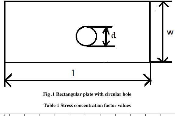
[image:2.595.163.450.231.421.2]Geometry considered for analytical calculations and Finite Element Modeling is depicted in Fig.1 and Geometric factors defined for various, diameters to width of plate, ratios are shown in Table 1.
Fig .1 Rectangular plate with circular hole
Table 1 Stress concentration factor values
Formulae used for calculations are depicted in eq. (1) – (5)
Geometric factor = . = (1)
Where d = diameter of hole, W= width of the plate, Kt = stress concentration factor
Kt = .
(2)
Tensile force = pressure *cross-sectional area (3)
Nominal stress = !"#$ %&'(
(*+,). (4)
Maximum stress = Kt × Nominal stress (5)
Rectangle plate with circular hole at 14MPa:
Considered data as given below Diameter of hole = 40mm Width of the plate = 100mm Thickness = 25mm
Pressure = 14MPa
Formulae:
Geometric factor = . =
SCF = .
/
0 0.05 0.1 0.15 0.20 0.25 0.30 0.35 0.40 0.45 0.50 0.55
607
Tensile force = pressure *cross-sectional area
Nominal stress = !"#$ %&'(
(*+,).
Maximum stress = SCF×Nominal stress
Procedure:
Geometric factor = . =
= 12
322
= 0.4 The ,
* ratio for stress concentration factor is taken from Table 1
Hence, SCF = 2.26
We know that
SCF = .
Hence,
Tensile force = pressure *cross-sectional area = 14×100×25
= 35000N
Nominal stress = !"#$ %&'(
(*+,).
= 45222
(322+12)×75
= 23.33MPa
Maximum stress = SCF×Nominal stress = 2.26×23.33
= 52.7MPa
Rectangle plate with circular hole at 16MPa:
Considered data as given below Diameter of hole = 40mm Width of the plate = 100mm Thickness = 25mm
Pressure = 16MPa
Procedure:
Geometric factor = . =
= 12
322
= 0.4
The ,
* ratio for stress concentration factor is taken from Table 1
Hence, SCF = 2.26
We know that SCF = .
Hence,
608
=40000N Nominal stress = !"#$ %&'(
(*+,).
= 12222
(322+12)×75
= 26.6MPa
Maximum stress = SCF×Nominal stress = 2.26×26.6
= 60MPa
Rectangle plate with circular hole at 18MPa:
Considered data as given below Diameter of hole = 40mm Width of the plate = 100mm Thickness = 25mm
Pressure = 18MPa
Procedure:
Geometric factor = . =
= 12
322
= 0.4
The ,
* ratio for stress concentration factor is taken from Table 1
Hence, SCF = 2.26
We know that
SCF = . Hence,
Tensile force = pressure *cross-sectional area = 18×100×25
= 45000N
Nominal stress = !"#$ %&'( (*+,).
= 15222
(322+12)×75
= 30MPa
Maximum stress = SCF×Nominal stress = 2.26×30
= 68MPa
Rectangle plate with circular hole at 20MPa:
Considered data as given below Diameter of hole = 40mm Width of the plate = 100mm Thickness = 25mm
Pressure = 20MPa
Procedure:
Geometric factor = . =
= 12
322
=0.4
The ,
609
Hence, SCF = 2.26
We know that
SCF = . Hence,
Tensile force = pressure *cross-sectional area = 20×100×25
= 50000N
Nominal stress = !"#$ %&'(
(*+,).
= 52222
(322+12)×75
= 33.33MPa
Maximum stress = SCF×Nominal stress = 2.26×33.33
= 75MPa
Finite Element Analysis of Rectangle Plate with Circular Hole
ANSYS12.0 is used to perform finite element analysis of Rectangle Plate with Circular Hole. Maximum and minimum stress obtained after analyzing are depicted in Fig.2 to Fig.5 for applied load of 14MPa, 16MPa, 18MPa and 20MPa respectively.
Fig.2 Maximum and minimum stress at 14MPa Fig.3 Maximum and minimum stress at 16MPa
610
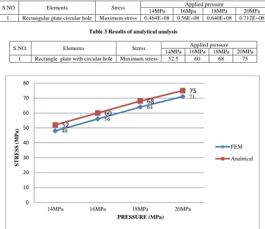
RESULTS AND DISCUSSION
A rectangular plate modeled with a concentric circular hole is subjected to four various loads. Table 2 and Table 3 represent results of FEM analysis and analytical results respectively. Graphical comparison of both results is depicted in Fig.6
Table 2 Results of FEM analysis
S.NO Elements Stress Applied pressure
[image:6.595.117.493.147.472.2]14MPa 16Mpa 18MPa 20MPa 1. Rectangular plate circular hole Maximum stress 0.484E+08 0.56E+08 0.640E+08 0.712E+08
Table 3 Results of analytical analysis
S.NO. Elements Stress Applied pressure
14MPa 16MPa 18MPa 20MPa 1. Rectangle plate with circular hole Maximum stress 52.5 60 68 75
.
Fig.6 Graphical comparison
CONCLUSION
In this paper a rectangular plate with concentric circular hole is modeled and various loads are applied to determine stresses induced. Finally analytical results obtained are validated with FEA results. So that composite material that consists of two or more combined constituents combined are suitable to increase the strength of the material.
REFERENCES
[1]Akbulut M; Sonmez F. O; Computers & Structures, 2008, 86(21), 1974-1982.
[2]Naik G N; Gopalakrishnan S; Ganguli R; Composite Structures, 2008, 83(4), 354-367.
[3]Walker M; Smith R E; Composite Structures, 2003, 62(1), 123-128.
[4]Silva R F; Rocha I B; Parente Júnior E; Melo A; Holanda Á. S. D; 2010, SILVA.
[5]Park C H; Saouab A; Bréard J; Han W. S; Vautrin A; Lee W I; Composites Science and Technology, 2009,
69(7), 1101-1107.
[6]Soykasap O; Karakaya Ş; 2007, Key Engineering Materials, 348, 725-728.
[7]Rangaswamy T; Vijayarangan S; Chandrashekar R A; Venkatesh T K; Anantharaman K; 2002, International
Symposium of Research Students on Materials Science and Engineering December, 4, 1-9.
[8]Yu W; 2005, International journal of solids and structures, 42(26), 6680-6699.
[9]Cárdenas D; Elizalde H; Marzocca P; Abdi F; Minnetyan L; Probst O; 2013, Composite Structures, 95, 53-62.
[10]Ahmed J K; Agarwal V C; Pal P; Srivastav V; 2013, International Journal of Innovative Technology and
Exploring Engineering, 3(6), 56-60.
48
56
64
71
52
60
68
75
0 10 20 30 40 50 60 70 80
14MPa 16MPa 18MPa 20MPa
S
T
R
E
S
S
(
M
P
a
)
PRESSURE (MPa)
FEM