Moment Capacity of L-connections in
PCSpconstruction
An Experimental
StudyPang
siaw
chinl,
Abdul
AzizAbdul
samad2, D.N.Trikha3,
.
r Re s e a," o
r,)i!,:x;? :;
li::ix
*?,T:"Ii;;
of E ng,
u pM
tProftetsor,
Facttlty of
Cirl-and Enviinmental Eig., KutTTHo
,'Professor, Dept. OfCivil
Eng., Faculty of Eng.,(IpM
'Professor&
President, Institute of Engineers, MalaysiaAbstract
The paper reports
the
results of an experimental s;tudy undertaken to developa
suitable cast-in-situ
momentresisting
vertical
connection between twointersecting precast concrete sandwich panels (PCSP).
Four
types of cast-in-situ L-connections have been studied. The reinforcementin
the connection isthe 5-7mm diameter steel
bar
extendedfrom
thereinforcing wire
meshin
the two panets. Eight specimens have beezn castin total;
there being two identicalspecimens
for
each typeof
the connection. Thesuitability of
each connectionhas
been
examinedas
regarded
its
cracking
moment,ultimate
momentcapacity and
ductility
measuredin
termsof
the surfacestrain
or
change inthe
included
angle
between
the
intersecting
panels
under
graduallyincreasingly moment. The
paper
describes the experimental investigation indetail and
establishesthe
superiority
of
the
looped-shape extended barconnection.
'Ouli'r(t'-
'
ku\
t.,
INTRODUCTION
As
early
as
1970s,ACI
committee408 pointed
out the
need for
research on
joints in
conventional concrete construction, asit
was found thateven when sufficient
anchoragelength
for
the
reinforcing steel
bar
wasprovided, the
reinforcing
steelbar did not
develop anticipated tensile stresstl].Further,
the
tension cracksat the
cornercould not
be prevented, eventhough a complicated reinforcement detail was adopted. As a result, Mayfield
carried
out
extensive investigationto
study the
joint
openingand
closing moment capacities[2,3].
Jackson[4]
and Abdul Wahab[5,6]
investigated thestrength characteristics
of
joints
obtainedby
intersecting U-bars. However, verylittle
guidanceis
available on momentor
shear capacitiesof
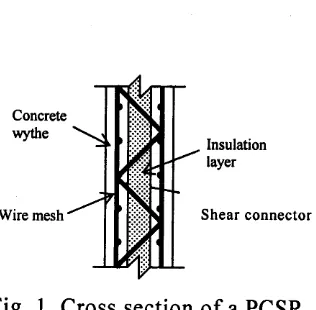
cast-in-situ connections between precast concrete panels. Construction using PCSP leadsto its own complexities as regards design
of
connections.A
PCSPconsists
of
an
insulation
layer
sandwiched between two reinforced concrete wythes interconnectedby
suitable shear connectors (seeFig.
l).
The structural behaviourof
the panels depends upon the strength andstiffness
of
the reinforced concrete wythes and the shear connectorwhile
the thermal resistanceof
the insulation layer g overns the insulative v alueof
theFig.
1. Cross sectionof
a PCSPIn a
typical
building,
three types
of
vertical
connections
areencountered; there are
L, T,
or X-connections, as shownin
Fig. 2. The presentstudy relates to L-connections only. External load-bearing walls are subjected
to wind
inducedlateral
forcesin
additionto axial
forces. The present paperpresents
only
part
of
the results
of
the
ongoing researchon the study
of
connectionsin
PSCP construction
as
related
to
cast-in-situ
connections subjected to moment only.L-joint
[image:3.590.256.414.71.226.2]t.,
TEST SPECIMENS
AND
MATERIALSA
total
of
eight
specimens representingfour
types
of
cast-in-situ
L-connectionshave been cast.
For
eachtype
of
connection,two
identicalspecimens have been tested under pure moment
to
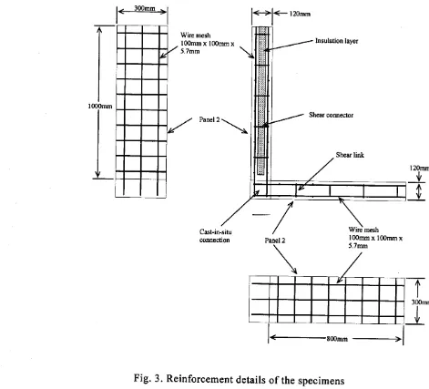
get average values.A
testspecimen
is
madeof
panelsI
and2
(Fig. 3);
panelsI
beinga
PCSP while panel2 is
a
solid
precast concrete panel.The length
of
panelsI
and2
is1000mm
and
800mm respectively,while
the
width
for
the
two
panels is300mm.
The overall
thicknessof
wytheswith
one 40mmthick
polystyrenelayet
in
the middle. The
reinforcement concrete wythesare
connected by continuous steeltruss
shear connectors spaced200mm
apart and madeof
5.7mm diametermild
steel bars. The shear connectors are so designed that thepanel
would not
fail
dueto
the failure
of
the
shear connectorsbefore
thefailure
of
the
cast-in-situ connection.The
reinforcementfor
the
reinforced concrete wythes consistsof
awire
meshwith
100mmx
100mm openings and5.7mm
bar
diameter.The
concretecover
to
the reinforcing
wire
mesh isl5mm.
Each reinforcing steel bar has been extended from the reinforcing wire meshto form
the connection so that the spacingof
thereinforcing
steel barsl*l
l-l-r2omm
I
I
I
000mm
I
Lr
Wire mesh l00mmx l00mmx
5.7mm
Cast-in-situ connection
l20mm
'1,
4
v
-T
I
300mm
l00mm x 100mm x
5.7mm
,
Panel 2
\
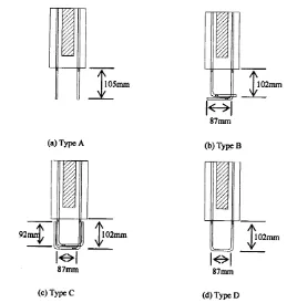
[image:5.591.64.535.115.542.2]Fig. 4 shows the reinforcement details
for
the four types of thecast-in-situ
connections, obtained
basically
by
overlapping
of
the
extendedreinforcing
steel barsfiom
the precast panelsin
the connection zone. Due tothe
inherent natureof
the
precast panels,the reinforcing
steel bars cannotextend continuously
from
panelinto
panel 2. Therefore, the actual anchoragelength
of
the extendedreinforcing
steel bars is restricted by thelimited
cast-in-situ connection area
-T-ll05mm
V
(a) Type A
lel
87mm
(c) Type C
Fig. 4. Types
of
cast-in-situ connections investigatedl<+l
87mm(b) Type B
l<>l
87mm
[image:6.590.77.458.288.688.2].t
It
is
seenthat the
anchoragelength
of
the reinforcing
steel barsfor
connection typeA is
l05mm.In
orderto
increase the anchorage lengthof
thereinforcing
steel bars,the
steel barsfor
joints
type
B
andC
were bent asshown
in
Fig.
4
thus permitting
anchoragelengths
of
about
l89mm
and28lmm
to
be
achieved.In
caseof
connectionD,
a
loop
has been createdthrough welding
of
aU
clampto
the reinforcing barsof
thewire
mesh. Therequired anchorage length, according to BS
8l
l0
is about 529mm.some pertinent material properties are given below:
Concrete:
compressive strength, fru = 39N/mm2; elastic modulus E. = 26kN/mm2
Plain steel mesh wire:
tensile strength ft = 650N/mmz; elastic modulus E,
=
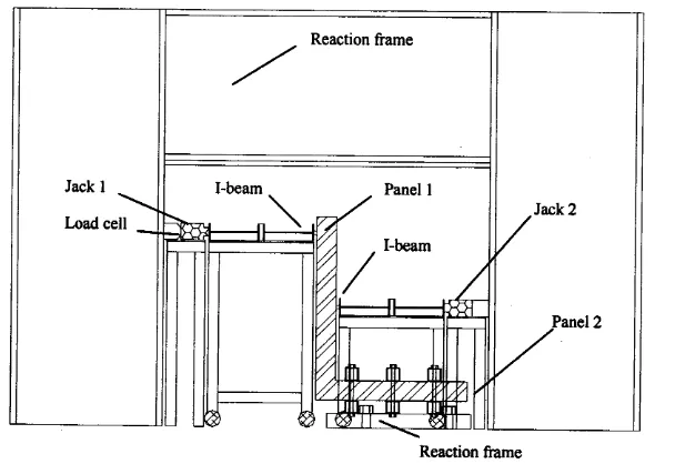
lggkN/mm2.TEST PROCEDURE
Two
specimensof
each typeof
thefour
connections have been testedunder
gradually
increasingpure
moment.The
setupis
shownin
Figure
5.Panel 2
of
the specimenis fixed
to the reaction frame.In
orderto
subject the1..
unit.
Thesetwo
forces
areconnection
is
subjectedto
aapplied
is
determined from reaction frame.by a
distanceof
0.55m,so that
theof
0.55PkNm.
The valueof
the
forcecell
located betweenjack
I
and
the separatedmoment
the
loadJ.,
t
Reaction frame
Fig. 5: Test set-up
for
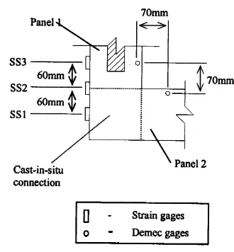
pure moment testFig.
6
showsthe
locationof
theelectric
resistance strain gages (gagelength:30mm)
usedto
measure surface concrete strains. Strain gagesSSI
islocated
on the
cast-in-situ concrete, strain gage SS2
is
located
on
theconstruction
joint
between panelI
and the cast-in-situ connection, and strain gage SS3is
locatedon panel
l.
Demec gage studs have been provided to [image:8.590.180.484.214.423.2]J,,
measure change
in
thehelp of a Demec gage.
included 90o angle between panels
I
and2 with
theCast-in-situ connection
[ - Strain gages
o - Demec gages
Fig. 6. Locations of the strain gages and Demec gages studs
RESULTS
AND
DISCUSSIONThe
performanceof
the four
typesof
connections undera
gradually increasingmoment has been
comparedby
measuringthe
changein
theincluded angle,
henceafter
called rotation
for
brevity, and
the
concretesurface
strain. The
averagevalue
of
the
observationson the
two
identicalspecimens of each connection type is presented.
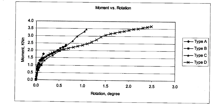
Figure 7 shows the moment vs. rotation graph
for
connection types A,B,
C andD.
From the graph,it
is
clear thatall
thefour
typesof
connectionsJ
[image:9.590.244.409.166.344.2]t
t.,
behave
in
a similar
mannerinitially,
the behaviour being essentially elasticand linear.
As
the momentis
increased, connection typeA
fails
suddenly sothat its behaviour is the least ductile as compares to the behaviour
of
the otherthree types
of
connections. Connectiontype
D
showsthe
highestductility
with
a longwell
defined increasingly flatter curve near failure.Fig. 7 . Moment vs. rotation
for
connection typesA,
B,c
and DTable
I
gives the valuesof
thefirst
cracking moment and themoment capacities
of
thefour
typesof
connections.It
is
seen that typeD
has almostsimilar first
cracking moment as typeB
andc,
itsultimate although ultimate
lvbnpnt vs. Flotation
tr
z
Y c
o
E
o
4.0
3.5
3.0
2.5
2.0
1.5 1.0
0.5
0.0
[image:10.591.107.512.272.477.2]moment capacities
is
respectively 53.9yo, 40.4% and 6.0Yo higher thanof
theconnection type
A,
B and C.Table
I
also gives the ratioof
the ultimate moment to thefirst
cracking momentfor
the four connection types, the ratio being indicative of the reservestrength.
It
is
seenthat
connectiontype
D
has much superior performance compared to connection typesA,
B and C.Table
l:
Results of pure moment testSpecimen Tvpe A Tvpe B Type C Type D
First cracking moment, M.,
(kNm) 1.16 r.59 1.65 r.54
Ultimate momentt, Mu
(kNm) r.70 2.20 3.47 3.69
Mu / M.,
t.47 1.38 2.10 2.40
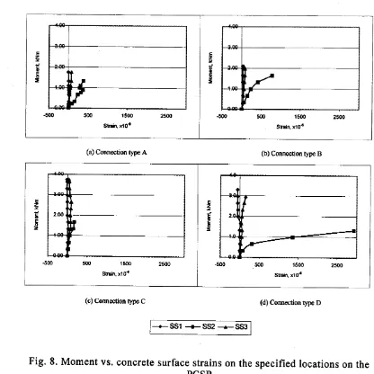
Fig.
8
shows
the
moment
vs.
concrete surface
strain
graphs for
connection types
A, B,
C andD.
It
is
seen that the location SS2 isjust
at theinterface
betweenthe in-situ
concreteand
panel
I
of
the
specimen and undergoes much greater strains than at the locations SSI and SS3. Further, thestrain a t I ocation S
52
shows a d uctile b ehaviour.It
ffiay, however, be n otedthat
strain gage SS2 becameineffective
dueto
the
appearanceof
the
crackunderneath before the
ultimate
moment could be reached. The strainSSI
is
4.,
4.,
measured
in a
region
of a
complex stress
state
not
liable
to
easyinterpretation.
(a) Connection type A (b) Connection type B
(c) Connection t)"e C (d) Connection t'"e D
--e- SS1
+-
SS2-p
SS3Fig. 8. Moment vs. concrete surface strains on the specified locations on the PCSP
\
r/
t
-500 500 1500 2500
E z v 5 E o = E z ! 6 E =
Sfain. x10' Strain, x10{
t
f
-500 500 1500 25oO
t
I
t
-500 500 1500 25oO
E z x c o I 6 = E z ! c o 5 =
StrCn, xl0{ Strain, xl0€
^J
{
-.-\
1
-5@ 500 tStD 25oO
[image:12.590.102.518.156.572.2]J..
CONCLUSION
PCSP
construction leads
to
inadequatelengths
at
the
cast-in-situvertical
connections dueto
relatively
smallerconnection
area. The presentstudy undertaken
to
develop a suitable connection indicates the superiority aswell
as the adequacyof
a loop type connection type D. The connection type Dalso
exhibits a ductile
behaviour under increasing momenttill
failure.
It
isalso
seenthat
all
the four
types
of
connectionsstudied
in
the
presentinvestigation have
similar
first
cracking moment capacities thereby showing the inertnessof
the anchorage bars before the onsetof
cracking. The ultimate moment of r esistanceof
the c onnection, h owever, depends on t he anchoragelength. The looped extended bars
into
the connection (TypeD)
increase the ultimate moment by about 120% over the open-ended extended bars (Type A).REFERENCES
1.
ACI
Committee 408.67(rl):857-867.
2.
Mayfield,
B.,
Kong,Corner Joint
Details 68(8):581-s89.1970.
opportunities in
Bond Research.ACI Jou,nal
F.
K.,
Bennison,A.,
and Davies,J.C.
D.
T..
lgTI
in
structural Lightweight concrete.
ACI
JournalJ.,
3.
Mayfield,
8.,
Kong, F.K.,
and Bennison,A..
I g7Z. Strength and Stiffnessof Lightweight Concrete corner . ACI
Journal
69(7): 420-427 .4.
Jackson,H
.
1995. Designof
Reinforced Concrete Opening Corner. The Structural Engineer 73(13): 209-213.5.
6.
Abdul-Wahab,
H.
M.
S. andAli,
W.
M..
1998. Strength and Behaviourof
Steel Fiber-Reinforced Concrete Corner under Opening Bending Moment. Magazine of Concrete Research 50@): 305-318.Abdul-Wahab,
H.
M.
S. and
Salman,S.
A.
R..
1999.Effect
of
Corner Angle onEfficiency of
Rinforced Concrete Joints under Opening Bending Moment. ACI StructuralJournal
96: I l5-l2I.
4.,
4.,
s..