© 2016, IRJET | Impact Factor value: 4.45 | ISO 9001:2008 Certified Journal
| Page 389
The stress distribution and Thermal stresses of Al Based Composite
piston by using finite element method
B. V. V. Prasada Rao
1and B. Siva Kumar
21, 2, Department of Mechanical Engineering
Aditya Institute of Technology and Management, Tekkali, Srikakulam Dist
---***---Abstract- In the present work describes the stress distribution and thermal stresses of three different aluminium alloy piston by using finite element method (FEM), testing of mechanical properties. The parameters used for the simulation are operating gas pressure, temperature and material properties of piston. The specifications used for this study of these pistons belong to four stroke single cylinder engine of Bajaj Kawasaki motorcycle. The results predict the maximum stress and critical region on the different aluminium alloy pistons using FEA. It is important to locate the critical area of concentrated stress for appropriate modifications. Static and thermal stress analysis is performed by using ANSYS 15. The best aluminium alloy material is selected based on results. The analysis results are used to optimize piston geometry of best aluminium alloys and composites.
Key words: FEA, Piston, Stress.etc,.
1. INTRODUCTION
Aluminium Metal Matrix Composites
The automotive industry recognizes that weight reduction and improved engine efficiency will make the greatest contribution to improved fuel economy with current power trains. This is evidenced by the increased use of aluminium alloys in engine and chassis components. Aluminium and magnesium castings in this sector have grown in leaps and bounds over the past five years to help engineers design and manufacture more fuel efficient cars.
The low density and high specific mechanical properties of aluminium metal matrix composites (MMC) make these alloys one of the most interesting material alternatives for the manufacture of lightweight parts for many types of vehicles. With wear resistance and strength equal to cast iron, 67% lower density and three times the thermal conductivity, aluminium MMC alloys are ideal materials for the manufacture of lightweight automotive and other commercial parts.
MMC’s desirable properties result from the presence of small, high strength ceramic particles, whiskers or fibres uniformly distributed throughout the aluminium alloy matrix. Aluminium MMC castings are economically competitive with iron and steel castings in many cases. However, the presence of these wear resistant particles significantly reduces the machinability of the alloys, making machining costs higher due mainly to increased tool wear. As a result, the application of cast MMCs to
components requiring a large amount of secondary machining has been somewhat stifled.
Most components do not require the high performance capability of aluminium MMCs throughout their entirety. An un-reinforced cast alloy may accommodate the stresses in these areas. Reinforcement of only the high stress regions of a component is referred to as selective reinforcement. This approach to component design and manufacture optimizes the material for the application, reduces the cost of the cast MMC part and lowers machining costs.
Selective reinforcement has been applied to the production of ring grooves and combustion bowl rim regions of pistons for both gasoline and diesel engines and integral cylinder liners for production gasoline engines. For the ring groove and cylinder liner applications, the reinforcement predominantly improves wear resistance. Application of short fibre reinforcement to the bowl rim increases its elevated temperature properties. The use of selective reinforcement in a clutch disk and ventilated brake disk has been considered but not yet entered production.
© 2016, IRJET | Impact Factor value: 4.45 | ISO 9001:2008 Certified Journal
| Page 390
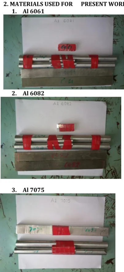
2. MATERIALS USED FOR PRESENT WORK 1. Al 6061
2. Al 6082
3. Al 7075
3. MODELING AND ANALYSIS OF ENGINE PISTON An Internal Combustion Engine is that kind of prime mover that converts chemical energy to mechanical energy. The fuel on burning changes into gas which impinges on the piston and pushes it to cause reciprocating motion. The reciprocating motion of the piston is then converted into rotary motion of the crankshaft with the help of connecting rod. IC engines are used in marine, locomotives, aircrafts, automobiles and other industrial applications.
3.1 PISTON:
A piston is a component of reciprocating IC-engines. It is the moving component that is contained by a cylinder and is made gas-tight by piston rings. In an engine, its purpose is to transfer force from expanding gas in the cylinder to the crankshaft via a piston rod. Piston endures the cyclic gas pressure and the inertial forces at work, and this
working condition may cause the fatigue damage of piston, such as piston side wear, piston head cracks and so on
Fig. 3.1. Model of a Piston
3.2. MATERIALS FOR PISTON:
The most commonly used materials for pistons of I.C. engines are cast iron, aluminium alloy (cast aluminium, forged aluminium), cast steel and forged steel. Many researchers stated that for a cast iron piston, the temperature at the centre of the piston head (TC) is about 425°C to 450°C under full load conditions and the temperature at the edges of the piston head (TE) is about 200°C to 225°C. and also for aluminium alloy pistons, TC is about 260°C to 290°C and TE is about 185°C to 215°C. 3.3. Characterization of Materials:
[image:2.595.35.237.99.540.2]The materials chosen are of pure Aluminium, 6061, Al-6082 and Al-7075 for this work for an internal combustion engine piston. The relevant mechanical and thermal properties of pure Aluminium, Al-6061, Al-6082 and Al-7075 aluminium alloys are listed in the following table
3.3.1. Engine Specifications:
The engine used for this work is a single cylinder four stroke air cooled type Bajaj Kawasaki petrol engine. The engine specifications are given in below table
PARAMETERS VALUES
Engine Type Four stroke, Petrol engine
Induction Air cooled type Number of cylinders Single cylinder
Bore 51 mm
Stroke 48.8 mm
Length of connecting
rod 97.6 mm
Displacement
volume 99.27 cm3
Compression ratio 8.4
Maximum power 6.03 KW at 7500 rpm
Maximum Torque 8.05 Nm at 5500 rpm
Number of
© 2016, IRJET | Impact Factor value: 4.45 | ISO 9001:2008 Certified Journal
| Page 391
3.4. Analytical Design:
IP = indicated power produced inside the cylinder (W) η = mechanical efficiency = 0.8
n = number of working stroke per minute = N/2 (for four stroke engine)
N = engine speed (rpm) L = length of stroke (mm)
A = cross-section area of cylinder (mm2) r = crank radius (mm)
lc = length of connecting rod (mm)
a = acceleration of the reciprocating part (m/s2) mp = mass of the piston (Kg)
V = volume of the piston (mm3) th = thickness of piston head (mm) D = cylinder bore (mm)
pmax = maximum gas pressure or explosion pressure (MPa)
σt = allowable tensile strength (MPa) σut = ultimate tensile strength (MPa) F.O.S = Factor of Safety = 2.25 K = thermal conductivity (W/m K)
Tc = temperature at the centre of the piston head (K) Te = temperature at the edge of the piston head (K) HCV = Higher Calorific Value of fuel (KJ/Kg) = 47000 KJ/Kg
BP = brake power of the engine per cylinder (KW)
m = mass of fuel used per brake power per second (Kg/KW s)
C = ratio of heat absorbed by the piston to the total heat developed in the cylinder = 5% or 0.05
b = radial width of ring (mm)
Pw = allowable radial pressure on cylinder wall (N/mm2) = 0.025 MPa
σp = permissible tensile strength for ring material (N/mm2) = 1110 N/mm2
h = axial thickness of piston ring (mm) h1 = width of top lands (mm)
h2 = width of ring lands (mm)
t1 = thickness of piston barrel at the top end (mm) t2 = thickness of piston barrel at the open end (mm) ls = length of skirt (mm)
μ = coefficient of friction (0.01)
l1 = length of piston pin in the bush of the small end of the connecting rod (mm)
do = outer diameter of piston pin (mm)
Mechanical efficiency of the engine (η) = 80 %.
Therefore, I.P = I.P =
I.P = 7.75 KW
Also,I.P = P x A x L x
I.P = P x x L x
Substituting the values from Table
We have 7.75 x 1000 = P x x (0.0488) x
So, P = 18.66 x
Or P = 1.866 MPa Maximum Pressure pmax = 10 x P = 10 x 1.866 = 18.66 MPa
From above calculations
3.4.1. Analytical design considerations for alloy piston:
Thickness of the Piston Head: th = 7.3 mm. Piston Rings: b = 1.33 mm and h = 1 mm. Width of Top Land: h1 = 7.3 mm.
Ring Lands: h2 = 0.75 mm Thickness of piston barrel at the Top end: t1 = 7.76 mm Open end: t2 = 2 mm.
Length of the skirt: ls = 30.6 mm Length of piston pin in the connecting rod bushing: l1 = 22.95 mm.
Piston pin diameter: do = 14.28
3.4.2. Creation of 3D models of piston using ANSYS Firstly Key points are generated. A straight line is drawn through Key points to form a half portion of the piston. Fillets are applied at corners. Area command is applied to generate half area of the piston. Extrude command is applied to generate volume of the piston. Finally, the hole is created.
Fig.3.2.3D model using ANSYS 3.4.3. Meshing of 3D model of Piston:
© 2016, IRJET | Impact Factor value: 4.45 | ISO 9001:2008 Certified Journal
| Page 392
Fig.3.3. Messing of 3D model.
3.5. Analysis of Piston:
Frictionless support at pin bore areas and fixed all degree of freedom. Downward pressure (18.66 MPa) due to gas load acting on piston head. The piston is analyzed by giving the constraints they are Pressure or structural analysis and Thermal analysis
3.5.1. Structural Analysis of Piston:
Combustion of gases in the combustion chamber exerts pressure on the head of the piston during power stroke. The pressure force will be taken as boundary condition in structural analysis. Fixed support has given at surface of pin hole. Due to the piston will move from TDC to BDC with the help of fixed support at pin hole. So whatever the load is applying on piston due to gas explosion that force causes to
boundary condition :
Fig.3.4. Boundary conditions Total deformation:
Fig.3.5. Total Deformation Equivalent stress:
Fig.3.6. Equivalent Stress Equivalent strain:
Fig.3.7. Equivalent Strain 3.5.2. Thermal analysis:
As the material used for designing of piston is Cast Iron. For a cast iron piston, the temperature at the centre of the piston head (TC) is about 425°C to 450°C under full load conditions and the temperature at the edges of the piston head
Fig.3.8. Applied temperatures on 3D model
© 2016, IRJET | Impact Factor value: 4.45 | ISO 9001:2008 Certified Journal
| Page 393
Fig.3.10. Temperature distribution
4. RESULTS
4.1. Mechanical properties:
S.NO PROPERT
Y MATERIAL USED 6061 6082 7075 1 Bending
strength (N/mm2)
10.23 12.598 14.173
2 Rupture
energy (J) 3.915 1.938 3.915
3 Modulus
of rupture (J/mm3)
8.8×10 -4
4.4×10 -4
8.8×10 -4
4 Notch
impact strength (J/mm2)
0.0489 0.02422 0.0489
5 Young’s modulus KN/mm2
6.385 5.7645 5.6209
6 Yield stress
KN/mm2 0.126 0.120 0.109 7 Ultimate
strength KN/mm2
0.236 0.244 0.120
8 Breaking stress
KN/mm2 0.211 0.216 0.103
9 Shear
strength KN/mm2
0.187 0.312 0.202
4.2. Results from FEA:
S.N o
PRESS URE/
LOAD (MPa)
MAT ERIA L
ANSYS RESULTS
DEFORM ATION
(mm)
STRES S
(MPa) STRAIN
1 18.33 AL –
6061
0.155 551.6 0.0077
2 18.33 AL –
6082
0.151 527.8 0.0074
3 18.33
AL-7075
0.147 496.5 0.0070
I. CONCLUSIONS
It is concluded from the results that the deformation stress and strain of Al-7075 is least among the three materials. Hence the inertia forces are less, which enhances the performance of the engine. The mechanical properties of this material were also good compared to other two, so further development of high power engine using this material is possible.
REFERENCES
[1].Hidehiko Kajiwara, at.al An analytical approach for prediction of piston temperature distribution in diesel engines
[2].V. Esfahanian, A. Javaheri, M. Ghaffarpour- Thermal analysis of an SI engine piston using different combustion boundary condition treatments
[3]. B. Bhandari, “Design of Machine Elements”, 3rd Edition, McGraw Hill.
[4]. Ajay Raj Singh, Dr. Pushpendra Kumar Sharma- Design, Analysis and Optimization of Three Aluminum Piston Alloys Using FEA International Journal of Material and Mechanical Engineering, Jan 2014.