© 2016, IRJET | Impact Factor value: 4.45 | ISO 9001:2008 Certified Journal | Page 1592
ANALYSIS AND EVALUATION OF STRUCTURAL SYSTEMS WITH
BRACING AND SHEAR WALL
S. Praveen kumar
1, G. Augustine Maniraj Pandian
21
M. Tech. Student, structural Engineering, Department of Civil Engineering, SRM University, Tamilnadu, India
2Professor, Department of Civil Engineering, SRM University, Tamilnadu, India
---***---Abstract -
The structure in high seismic areas may besusceptible to the severe damage. Along with gravity load structure has to withstand to lateral load which can develop high stresses. Now a day, shear wall and steel bracings in R.C structure is most popular system to resist lateral load due to earthquake, wind, blast etc. It is found that the X type of steel bracing system significantly contributes to the structural stiffness and reduces the maximum inter story drift, lateral displacement. The shear wall is one of the best lateral load resisting systems which is widely used in construction world but use of steel bracing will be the viable solution for enhancing earthquake resistance. Shear walls are incorporated in building to resist lateral Forces and support the gravity loads. RC shear wall has high in plane stiffness. Positioning of shear wall has influence on the overall behaviour of the building. For effective and efficient performance of building it is essential to position shear wall in an ideal location. The computer aided analysis is done by using E-TABS to find out the effective lateral load system during earthquake in high seismic areas. The performance of the building is evaluated in terms of Lateral Displacement, Storey Drifts, Base shear and time period. The main purpose of this study is to analyse the RCC shear wall and Rigid-bracing framed structure and also to compare the top storey displacement variation, cost per panel and weight of shear wall and bracing in the building.
Key Words: Seismic analysis, Shear wall, X-Bracings, Equivalent static method, Response spectrum method, E-TABS
1. INTRODUCTION
Reinforced concrete building can adequately resist both horizontal and vertical load. Whenever there is requirement for a multi-storey building to resist higher value of seismic forces, lateral load resisting system such as shear wall, bracing systems should be introduced in a building.
Rigid-Bracings systems are one of the lateral load resisting systems which have got structural importance especially in reinforced concrete buildings. The use of steel bracing in RC structures has some advantages such as it is relatively cost-effective, does not significantly add the structural weight, is easy in application and can be
customized with the necessary strength and rigidity. Therefore, the use of steel bracing systems for retrofitting reinforced concrete is a frame with inadequate lateral resistance is attractive.
Vertical plate like RC wall introduced in building in addition to beam, column and slab are called shear wall. Shear wall can be provided both along the length and width of the building. Properly designed building with shear wall has shown good performance in past earthquake. Rigid frames are considered economical for buildings of up to 25 stories, if it’s combined with shear walls, the height may extend up to 50 stories or more. Shear walls behaviour depends upon the material used, wall thickness, wall length, wall positioning in building frame also. The main purpose of this study is to analyse the RCC shear wall and Rigid-bracing framed structure.
1.1 Rigid Frame
The word rigid means ability to resist the deformation. Rigid frame structures can be defined as the structures in which beams and columns are made monolithically and act collectively to resist the moments which are generating due to applied load. Rigid frame structures provide more stability. This type of frame structures resists the shear, moment and torsion more effectively.
1.2 Braced Frame
A Braced Frame is a structural system which is designed primarily to resist wind and earthquake forces. Members in a braced frame are designed to work in tension and compression. Braced frames are almost always composed of steel members. In braced construction, beams and columns are designed under vertical load only, assuming the bracing system carries all lateral loads.
1.3 Shear Wall
© 2016, IRJET | Impact Factor value: 4.45 | ISO 9001:2008 Certified Journal | Page 1593
2. BUILDING MODELLING AND ANALYSIS
E-TABS2015 software is used to develop 3D model and to carry out the analysis. In this study, (G+9), (G+14) and (G+19) storey RC buildings of 3 Shear wall models and 3 X-Braced models are fixed at base. The building has plan dimensions of (15 m x 15 m) and symmetric about both X and Y directions to avoid torsional effects. The storey height is 3m in the entire floor including the ground Floor. Building is designed according to IS: 456-2008 and earthquake loading is applied as per IS: 1893-2002. Equivalent static method and Response spectrum method is used for seismic analysis Seismic parameters considered for this study are as follows.
Zone factor for seismic zone V = 0.36
Soil site factor for medium soil condition = 2 Importance factor = 1.5
Response reduction factor = 5 Damping ratio = 0.05
[image:2.595.311.561.130.385.2]For all the models, live load and floor finish are taken as 3 kN/m2 and 1 kN/m2 respectively.Load combinations are applied as per the recommendation of Indian standard codes. In seismic weight calculations, 25 % of the floor live loads are considered. M25 grade concrete and Fe415 structural steel is used.
Table -1: Building Description
No. of
Stories G+9 G+14 G+19
Beam
size 0.3m x 0.45m 0.3m x 0.5m 0.3m x 0.6m
Column
size 0.45mx 0.45m 0.5m x 0.5m 0.6m x 0.6m
Slab thickness
0.23m
Shear wall thickness
0.15m
Steel bracing
ISA 150 x 150 x 15
In this study, total six models are analyzed. Three Shear wall models
Three X-braced models
ISA 150 x 150 x 15 double angle back to back steel sections is used as bracing members.
The location of shear wall and bracings in RC buildings are as shown in Fig. [1-4]
[image:2.595.34.290.421.623.2]2.1 Shear wall Model
Fig. 1: Plan view of Shear wall Building
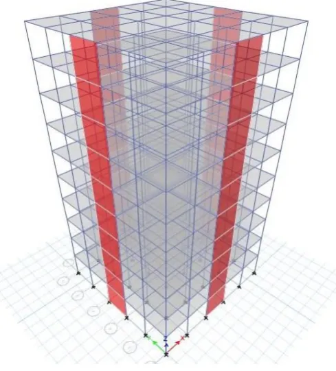
Fig. 2: 3D view of RC Building with Shear wall
[image:2.595.312.557.429.700.2]© 2016, IRJET | Impact Factor value: 4.45 | ISO 9001:2008 Certified Journal | Page 1594
2.2 X-Braced Model
[image:3.595.311.554.199.359.2]Fig. 3: Plan view of X–Braced building
Fig. 4: 3D view of RC Building with X-Bracing
3. RESULTS AND DISCUSSIONS
From the results of analysis, it’s observed that the value of base shear, storey drift and top storey displacement in x and y direction are same.
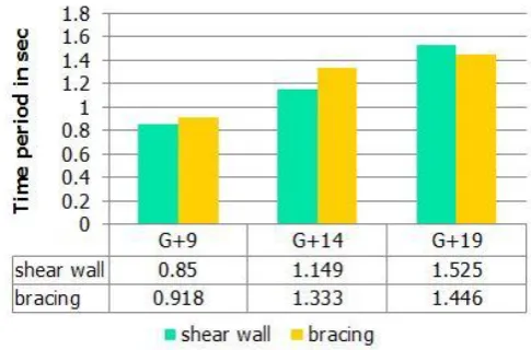
3.1. Fundamental Time Period
The time period of all models is as shown in chart –1.
Chart -1: Time period of all models
3.2. Base Shear
Base shear of all models using equivalent static method and response spectrum method is shown in chart -2 & 3.
© 2016, IRJET | Impact Factor value: 4.45 | ISO 9001:2008 Certified Journal | Page 1595 Chart -3: Base shear using Response Spectrum Method
3.3. Storey Drift
Table -2: Storey Drift of all models.
[image:4.595.314.558.343.491.2]3.4. Top Storey Displacement
Table -3: Top Storey Displacement of all models.
3.5. Top Storey Displacement Variation
The percentage variation in Top storey displacement of Shear wall and X-braced building of all models using Equivalent static method and Response spectrum method are shown in below chart -4.
Chart -4: Percentage variation in Top Storey Displacement
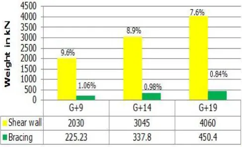
3.6. Weight Comparison
Total weight of shear wall and bracing of all models are compared and the Percentage of addition of shear wall and bracing to the total weight of building is shown in chart -5.
Chart -5: Weight Comparison of all models
3.7. Cost Comparison
Considering 3 x 3 m panel of all models, estimated cost of shear wall and bracing in the building including cost of material, formwork, fabrication, labour, etc.., is compared and shown in below chart -6.
[image:4.595.312.551.612.733.2]© 2016, IRJET | Impact Factor value: 4.45 | ISO 9001:2008 Certified Journal | Page 1596
4. CONCLUSIONS
The following conclusions are drawn based on present study
Storey drift of the Shear wall and steel braced model is within the limit as clause no 7.11.1 of IS-1893 (Part-1):2002.
Lateral displacement variation of 15 Storey models shows 15.46%, which is higher than other two types of models.
From the results of G+19 models, the top storey displacement of X-Braced model is 5.59% lesser than shear wall model. Therefore it’s recommended to provide bracing for buildings more than 15 storeys.
It’s observed that weight of shear wall is 88.9% higher than bracing in all three types of modelled structure.
Comparing the cost, bracing is 30.1% higher than shear wall for one panel.
REFERENCES
[1] Anil Baral, Dr. Yajdani SK., “Seismic Analysis of RC Framed Building for Different Position of Shear Wall”, International Journal of Innovative Research in Science,Engineering and Technology, Vol. 4, Issue 5, May 2015.
[2] Chandurkar P. P., Dr. Pajgade P. S., “Seismic Analysis of
RCC Building with and without Shear Wall”,International
Journal of Modern Engineering Research (IJMER), Vol. 3, Issue. 3, May - June 2013 pp-1805-1810.
[3] IS 456: 2000. “Indian Standard Code of Practice for plain and reinforced Concrete”, Bureau of Indian Standards, New Delhi, 2000.
[4] IS 1893(Part-I): 2002 “Criteria for Earthquake Resistant Design of Structures” Part-I General Provision and Buildings (Fifth Revision). Bureau of Indian Standards, New Delhi, 2002.
[5] IS 875 (Part-2)-1987 “Code of Practice for Design Load (other than earthquake) for buildings and structures”, Imposed loads.
[6] Kevadkar D., P.B. Kodag, “Lateral Load analysis of RCC
buildings” International Journal of Modern Engineering Research (IJMER) Vol.3, Issue.3, May-June. 2013. [7] Kulkarni J. G., Kore P. N., Tanawade S. B. “ Seismic
Response of Reinforced Concrete Braced Frames” International Journal of Engineering Research and Applications, Vol. 3, Issue 4, July - Aug 2013, pp.1047-1053.
[8] Shachindra Kumar Chadhar, Dr. Abhay Sharma,
“Comparative Study of RC Moment Resisting Frame of Variable Heights with Steel Bracing and Shear Wall”, International Journal of Civil and Structural Engineering Research, Vol. 3, Issue 1, pp: (220-221), April - September 2015.
[9] Umesh.R.Biradar, Shivaraj Mangalgi. “Seismic Response
of Reinforced Concrete Structure by Using Different Bracing Systems”, International Journal of Research in Engineering and Technology, Volume: 03 Issue: 09, Sep-2014.
[10] Viswanath K.G., Prakash K.B. and Anant Desai, “Seismic