An Efficient Clustering Technique for Deterministically
Deployed Wireless Sensor Network
Ankit K Jain, N Purohit
,
PhD.,
K K Pandey,Akshansh Jain, Harsh Bansal and Harshit
Indian Institute of Information Technology Allahabad, India
ABSTRACT
The deployment mechanism in wireless sensor networks (WSN) affects the coverage, connectivity, bandwidth, packet loss, lifetime of network, etc. features [1]. Depending upon the application, the sensor nodes are deployed in either random or deterministic fashion, accordingly WSN has different requirements and features. In this work, a new clustering technique, Energy Efficient Deterministic Cluster-Head Selection Algorithm (E2DCH), is proposed for deterministically deployed WSN. Better coverage with less number of nodes, minimum traffic from nodes to base station, balanced energy consumption are the main features of E2DCH to improve life time of WSN. The proposed algorithm uses dynamic routing from nodes to respective cluster head by considering the number of nodes and residual node energy of all the involved nodes. It includes an efficient technique for reorganizing the clusters. Analysis and simulation results demonstrate the correctness and effectiveness of the proposed algorithm.
Keywords:
Wireless Sensor Network, Clustering, Deterministic topology, connectivity, coverage1.
INTRODUCTION
Wireless sensor network is an organization of sensor nodes that interacts with each other remotely and is spread at random or manually over an area to sense environmental or physical conditions such as pressure, vibration, temperature, sound, motion or pollutants and to collaboratively pass their data to a main location (base station or sink) through the network.
WSNs have a huge number of sensor nodes and each node can intercommunicate with one or several nodes by the radio link. Low cost design of a sensor network is essential necessity. Sensor nodes consist of three parts: an external energy source (battery), an electronic circuit containing microcontroller for computing the sense information and a transceiver with an association of antenna. Sensor network have the ability to manage dynamic topology and handle with node failures. Wireless sensor network was first introduced 1990 for the commercial purpose. The sensors are coordinating among themselves to build a communication network like one multi-hop network or a hierarchical system with several clusters and cluster heads. The sensors could be spread randomly in ruthless environments such as a battleground or it can be deterministically placed at defined locations. A sensor node is having a restricted sensing scope and also communicating range.
Recently wireless sensor network adopted in many industrial real time monitoring application like industrial process monitoring, harmful radioactive material monitoring etc. Sensors are pretty valuable in the field of environmental
monitoring. In the field of environment monitoring, they used to discover harmful activity in the forest like wild creature preservation, fire welfare and greenery conservation. Some other application include: Greenhouse supervising, earthquake monitoring, different type of pollution like air, soil, water, radioactive monitoring, meteorological and geophysical inquiry, habitat monitoring of creatures, flood alert providing etc. WSNs have a lot of application in agriculture. There are many projects are proceeding to preserve the environment [2].
The major challenges of wireless sensor network fading bit error rate, per node energy consumption, localization, and deployment strategy selection [3] [4], the deployment strategy plays a major role in all above challenges.
The deployment strategies in sensor network plays important role in over all energy consumption. Most of the time it has been observed that sensor nodes are randomly deployed using Poisson or Gaussian distribution. In such kind of deployment deployed nodes organize themselves in a cluster this kind of scheme is also called hierarchical clustering [5]. In the [6], [7], [8], [9] the authors are trying to provide the coverage with reducing the energy consumption. In the [10] the coverage is provided by moving a sensor node. The deployment strategies proposed in [11] a deployed node give instruction to its neighboring node to gain a maximum distance between them to provide maximum coverage and proper connectivity is also remain between them. The other proposed scheme [12] in which the maximum coverage is provided by less amount of sensor movement. There is another deployment technique [13] in which authors proposed three different protocols to provide high level of coverage with minimum movement. There are few deterministic protocols [10] and [14] which designed to provide maximum coverage.
In this work deployment strategy is deterministic; nodes are deployed according to pre decided topology. The advantage of deterministic deployment is uniform coverage and less complexity [15].
2.
Deterministic Deployment Techniques
The deployment of sensors is a key consideration as it affects the performance of system [16]. The deployment of sensor node is square grid. The key features of deterministic deployment are the following,
1-Sensor nodes should deploy in a specific fashion so that chances of data packet collision minimized.
2-In order to detect event as early as possible, the sensor nodes should effectively cover the region of interest. 3-Sensor node deploy such that it will cover whole region in minimum number of nodes.
2.1
Network Architecture & Topology
Design
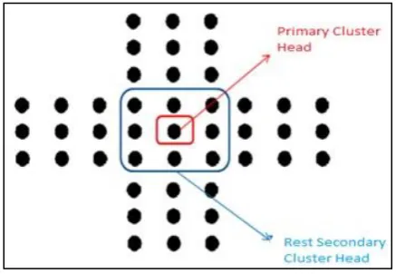
[image:2.595.53.272.304.455.2]In the proposed topology, nodes are deployed 8 secondary cluster head surrounding the single cluster head in a 3×3 square matrix and 36 total sensor nodes are deployed around this network. Nine sensor nodes are in each direction in 3×3 square matrix.
Figure 1 Proposed Topology
Assumptions of the topology are as follows:-
1-Nodes can take and transmit data to and from neighboring nodes only.
2-The range of motes is set in such way that even neighboring diagonal too is not allowed to take and transmit data from each other.
3-Primary base station has the authority to send data to any of node deployed in this topology.
4-Secondary cluster head are used to allocate the load equally amongst the boundary nodes. Benefits of this topology are following
Data fusion: In Data fusion several messages are aggregated to construct a single which leads to fewer messages overhead in the network. In this topology, each mote of a column sends a message to the next mote of its respective row if it finds concentration of gases or radioactive radiation is above than threshold. The next column motes, if the also find their surrounding concentration of gases or radioactive radiation is above than threshold, fuse their data in the message they received from the previous mote & then send to next node. In this way, data fusion takes place.
Balanced energy consumption: In proposed framework, sensor nodes sends regular information message to secondary
cluster head to balance energy consumption. The secondary cluster head motes then forward the data to the main cluster head; in this way energy consumption is balanced in the node closer to cluster head.
Fewer messaging overhead: In proposed design, the motes send data to base station only when they find their surrounding concentration of gases or radioactive radiation is above than threshold else they do not send any data. So, only useful information is passed to base station.
Easy to expand: The complete network is very easy to expand and viewed as a unit cell and the complete area can be covered by combining these unit cells to make complete lattice.
Optimum utilization of base station range: Proposed topology is utilizing the complete base station range. Since, the data can be send and receive from base station in all the direction so it is covering a greater amount of area comparing to previous topology
Simple algorithm for best path: The maximum possible paths through which data packet can be transmitted are six. Due to this much less processing time is required by the sink in order to decide the best possible path for data transmission. Hence, the whole system gets speed up.
2.2
Intra Cluster Communication Protocol
path or not. . The nodes which are not in path run Timer of 15 min. & go to “SLEEP” state.
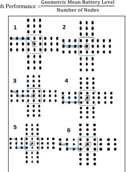
Path Performance =
[image:3.595.65.276.100.387.2]Figure 2 Six Possible paths from node to Cluster Head
2.3
Energy Efficient Deterministic Cluster
Head Selection Algorithm (E
2DCH)
This section focuses on cutting the power consumption of wireless sensor networks. Here a new approach is being presented to boost lifetime of sensor networks. Cluster Head consumes more energy as compared to other nodes, because it consumes energy for aggregation of data and for transmitting aggregated data to base station [17, 18]. In this approach cluster head is continuously changing its position and move topology in a deterministic manner enhancing the lifetime of network. This algorithm ensures that after a particular time interval all nodes will become In presented topology cluster head is positioned at the center. The algorithm for choosing cluster head is as following:
Input: Total number of Nodes N in a cluster
Output: After a particular time interval, all the nodes will become cluster heads in turn.
Begin
1. Sensor nodes are deterministically deployed in a square grid. Nodes are grouped into clusters.
Repeat step 2 to 5 for N/2 rounds
2. In the case of event detection, the nodes transmit data to their respective cluster heads which eventually gets transferred to the base station
3. Perform a right-shift on the position of all the cluster-heads
4. Now again data could be transferred as mentioned in step 2
5. Perform an Upward-shift on the position of all the cluster-heads
End
End of loop
3 The Simulation Framework
MATLAB has been used as a simulator in my thesis work .In simulation the field of 18x18 dimensions has been taken and number of sensor nodes are 324. In this various parameters of node and their default values have been defined. Nodes are deployed in deterministic manner. Nodes are deployed at a fixed distance with each other. The vertical and horizontal coordinates of every sensor nodes must be preserved to calculate the energy dissipation in data transmission. In the simulation initially 4 full cluster and 8 partially cluster present. Each node has 0.5 joule energy. In simulation this value is being used but any value can be assign. It is necessary that all sensor nodes must have equal energy earlier any action or event occurs. Sink has been placed corner of the field. Table 1 shows some detail about the energy consumption in numerous operations [5].
Operations Energy Consumption
Electronics energy (Eelec) 50 nJ/bit Amplifier energy (efs)
(emp)
10 pJ/bit/m2 0.0013 pJ/bit/m4 Energy for data aggregation (EDA) 5 nJ/bit/signal
Table 1: Radio Characteristic
The packet format of message is shown in figure 3 [15]. There are three fields: header, information field and trailer. The header field generally contains the identification number of source and destination, packet sequence number, message type, in WSN header is of very few bytes. Data field contains data or control information depending upon the type of message and trailer contains the cyclic redundancy check bits. Header Information or Data Trailer
Fig 3 Packet format of message
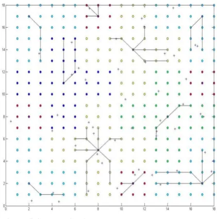
Figure 4 Deterministically Deployed Sensor Nodes
In fig 4 there are 324 sensor nodes deterministically deploy. To distinguish between clusters there are different color used.Distance between two nodes is 1 m in x and y direction and diagonally and sensing range of each node is /2 m so it will cover whole area. There are some event generated in simulation and each event has some value. If a particular event in the range of one or more nodes then and its value greater then a threshold level than nodes will send packets to cluster head in multi-hop communication.
Figure 5 Communication between nodes and cluster head
In fig 5 each sensor node sense values of event if event within its sensing range and its value is greater than some threshold then its send packet to its respective cluster head by intra cluster routing technique. Routing technique is according to proposed algorithm.
After getting values from nodes each cluster head aggregate data and send a value to Base station, it is showing in fig 6. Base station is placed at the corner of field. Cluster head send
[image:4.595.314.544.115.353.2]packet diagonally to next cluster head in a multi hop manner. Sink collect information from all the cluster head which got some thread from its node. After aggregating information sink know that all position where the events detected.
Figure 6 Cluster Heads transmit packet to base station
After getting values from nodes each cluster head aggregate data and send a value to Base station, it is showing in fig 6. Base station is placed at the corner of field. Cluster head send packet diagonally to next cluster head in a multi hop manner. Sink collect information from all the cluster head which got some thread from its node. After aggregating information sink know that all position where the events detected.
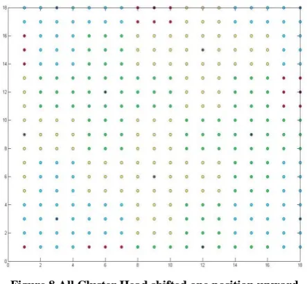
Figure 7 All Cluster Head shifted one position right
[image:4.595.317.535.438.662.2] [image:4.595.55.279.439.665.2]Figure 8 All Cluster Head shifted one position upward
Then again entire structure shift one position upward as shown in fig 8 and again node sense data and send to cluster head and cluster head send to BS. Then after entire structure shifted one position right and then one position upward. In simulation after completion of 18 right shift and upward shift, means on 19th round structure will appear exactly same as 1st same as it appear in round. It can be said that in 18 round all node will become cluster head. so it is a very energy efficient protocol, this protocol guaranteed that all node will become cluster head. The energy of the node is computed after every transmission of data and check the available energy of the node. So that it is able to further participate in the operation phase of the network.
4 The Result and Discussion
[image:5.595.325.526.75.263.2]Sensor nodes are deterministically deployed and it is assume that if any event detected then nodes always communicated with cluster heads. Two simulations with varying number of nodes is being done, 2500 rounds in both simulations is being taken. In first simulation 324 nodes is being taken in the beginning. After 2500 round there are 112 nodes are alive is showing in figure 8. First node died at round number 1862. In second simulation 400 nodes is being taken, in the second simulation the first node is die at round number 1878 and after 2500 round 128 nodes are alive. Second simulation is showing in 9.
Fig 9 Lifetime of Network at n=324
Fig 10 Lifetime of Network at n=400
5 Conclusion and Future Work
Given work proposes a unique design of wireless sensor networks in efficient deterministic deployment. The proposed design is based on the square grid deployment. The node deployment is uniform and cover whole region. The proposed routing algorithm is simple and it choose maximum energy path. After that an energy efficient deterministic cluster head selection protocol is presented, which ensure that every node will become cluster head after a fixed time interval. The results showed that this approach has been successful in achieve a good lifetime of networks. The proposed technique is useful where the random deployment of node is not feasible such as industries and in vehicular networks. We have not considered the effect on the data rate while choosing the best path, we also not considered other parameter while choosing the best path this can be considered as a future work.
6 REFERENCES
[1] I. Akyildiz, W. Su, Y. Sankarasubramaniam, and E. Cayirci, “A survey on sensor networks,” IEEE Communications Magazine, vol.40, no. 8, pp. 102–114, Aug. 2002.
[2] C. F. García-Hernández, P. H. Ibargüengoytia-González, J. García-Hernández, and J. A. Pérez-Díaz, “ Wireless Sensor Networks andApplications: a Survey,” International Journal of Computer Science and Network Security (IJCSNS), vol.7 no.3, Mar. 2007.
[3] Chee-Yee Chong, and S. P. Kumar, “Sensor Networks: Evolution, Opportunities, and Challenges,” Proceedings of IEEE, vol. 91, no. 8, Aug. 2003.
[4] A.Alemdar and M. Ibnkahla,”Wireless sensor networks: applications and challenges,” ISSPA, 2007, pp. 1-6.
[5] W. B. Heinzelman, A. P. Chandrakasan, and Hari Balakrishnan, “An Application-Specific Protocol Architecture for Wireless Microsensor Networks,”IEEE Trans. Wireless Commun, vol. 1.
[image:5.595.56.273.574.748.2][7] M. Cardei and D. Du, “Improving Wireless Sensor Network Lifetime through Power Aware Organization”, Wireless Networks , Volume 11 Issue 3, May 2005 [8] M. Cardei, J. Wu, M. Lu, and M. Pervaiz, “Maximum
network lifetime in wireless sensor networks with adjustable sensing ranges”. In Proceedings of the IEEEInternational Conference on Wireless And Mobile Computing, Networking And Communications (WiMob), 2005.
[9] H. Zhang, H. Wang, and H. Feng, “A Distributed Optimum Algorithm for TargetCoverage in Wireless Sensor Networks”, 2009 Asia-Pacific Conference on Information Processing.
[10] A. Howard, M. J. Matari´c, and G. S. Sukhatme, “An incremental self deployment algorithm for mobile sensor networks,” Autonomous Robots, vol. 13, no. 2, pp. 113– 126, Sep. 2002.
[11] S. Poduri and G. Sukhatme, “Constrained Coverage for Mobile Sensor Networks”, IEEE International Conference on Robotics and Automation, pages 165-172 April 26- May 1, 2004, New Orleans, LA, USA
[12] A.Osmani, M.Dehghan, H. Pourakbar, and P. Emdadi, “Fuzzy-Based Movement Assisted Sensor Deployment Method in Wireless Sensor Networks”, 2009 First International Conference on Computational Intelligence, Communication Systems and Networks.
[13] G. Wang, G. Cao, and T. La Porta, “Movement-Assisted Sensor Deployment,” in Proc. of the 23rd IEEE INFOCOM, 2004.
[14] X. Bai, Z. Yun, D. Xuan, T. Lai, and W. Jia, “Optimal Patterns for Four-Connectivity and Full Coverage in Wireless Sensor Networks”, IEEE Transactions on Mobile Computing, 2008.
[15] Y. Sankarasubramaniam, I. F. Akyildiz, and S. W. McLaughlin,“Energy efficiency based packet size optimization in wirelesssensor networks,” IEEE 1st International Workshop on SensorNetwork Protocols and Applications, Alaska, USA, May 2003.
[16] S. Abdel-Mageid, R.A.Ramadan,” Efficient deployment algorithms for mobile sensor networks” IEEE international on Autonomous and Intelligent System, Publication Year: 2010, Page(s): 1 – 6
[17] R. Ghosh, S. Basagni. “Napping backbones: energy efficient topologycontrol for wireless sensor networks” Radio and Wireless Symposium, 2006 IEEE Publication Year: 2006 , Page(s): 611 – 614