ISSN(Online): 2319-8753 ISSN (Print): 2347-6710
I
nternational
J
ournal of
I
nnovative
R
esearch in
S
cience,
E
ngineering and
T
echnology
(An ISO 3297: 2007 Certified Organization)
Website: www.ijirset.com
Vol. 6, Issue 5, May 2017
Copyright to IJIRSET DOI:10.15680/IJIRSET.2017.0605219 8623
Comparative Study on RC and CFFT Bridge
Columns Subjected to Impact and Cyclic
Loading Conditions
Aswathi Devika M S
1, Geethu R Babu
2P.G. Student, Department of Civil Engineering, SCMS School of Engineering and Technology, Kerala, India1 Associate Professor, Department of Civil Engineering, SCMS School of Engineering and Technology, Kerala, India2
ABSTRACT: This paper outlines a numerical model built using commercially available software to predict the response of Concrete filled Fibre Reinforced Polymer (FRP) Tubes (CFFTs) and regular round reinforced concrete members to impacts and cyclic load responses .The models were verified against drop weight impact test lab measurements. A parametric study was conducted using the verified models to investigate the effects of layer, reinforcement ratio on CFFT and comparing the same with the conventional type.
KEYWORDS: CFFT, Displacement control method, Impact loading, Cyclic loading I. INTRODUCTION
Concrete-Filled Fibre Reinforced Polymer (FRP) Tube (CFFT) system has been widely investigated as a durable and cost-effective alternative design for more robust bridge columns. The current AASHTO guide specifications are limited to nonductile, unreinforced CFFT elements. Concrete-filled Fibre-Reinforced Polymer (FRP) tube (CFFT) columns were first introduced as a highly durable alternative to conventional RC bridge piers by Mirmiran and Shahaway (1996).Although glass FRP (GFRP) has shown some vulnerability to degradation in alkaline environments, the use of certain resin matrices can enhance the durability of GFRP components for structural applications. Additionally, MK Plastics (2011) has published a table showing GFRP to be resistant to nearly 300 corrosive substances, including several chlorides and Sulphates that are the main proponents of corrosion in bridge structures. The durability of the composite pipes is further exhibited through several instances in which they have stayed in service in highly corrosive environments for over 30 years.Studies summarize the findings of blast, fire, and seismic experiments performed on CFFT specimens containing minimal longitudinal reinforcement. The residual axial load carrying capacities of damaged reinforced concrete (RC) and CFFT columns are obtained as a measure of robustness, and estimated restoration times and repair costs are presented for each type of column and each hazard.
This study comprises of how the FRP wrapped structure will respond towards different hazardous situations. The different situation here considered is impact effect in terms of blast and then cyclic loading to find the seismic response. The impact load acts within fraction of time and its response varying with thickness of FRP layers is observed. Second study is about cyclic loads that act on the column for each varying layer thickness. In each case the percentage variation in displacement is noted to get the efficiency of FRP layer.
Paper organized as follows, section II explains related work on CFFT structures, the seismic behaviour of CFFT system.In section III axial load capacities of CFFT and RC column is studied through conducting an experimental setup. In section IV and V the effect of impact and cyclic loading is studied. In section VI the conclusion of all the above studies is made.
II. SEISMICPERFORMANCEOFCFFTCOLUMNS
ISSN(Online): 2319-8753 ISSN (Print): 2347-6710
I
nternational
J
ournal of
I
nnovative
R
esearch in
S
cience,
E
ngineering and
T
echnology
(An ISO 3297: 2007 Certified Organization)
Website: www.ijirset.com
Vol. 6, Issue 5, May 2017
Copyright to IJIRSET DOI:10.15680/IJIRSET.2017.0605219 8624
cast-in-place CFFT column with starter bars, a precast CFFT column with grouted starter bars, and a precast CFFT column with unbonded posttensioned rods. The columns were subjected to a constant axial load and a pseudo-static lateral load. All proposed joints proved feasible in construction and robust under extreme load conditions. FRP tube, when secured properly in the footing, showed great influence on the seismic performance of the column by providing both longitudinal reinforcement and hoop confinement to the core concrete. The CFFT columns exhibited significant improvement over traditional RC columns in both ultimate strength and ductility.The study also showed that practices of the precast concrete industry can be easily and effectively implemented for the CFFT column construction.The benefits include high strength-to-weight and stiffness-to weight ratios, resistance to electro-chemical corrosion, and versatility of fabrication. A primary challenge, however, is to make the application cost effective. Outside of repair projects, the initial cost of FRP has made this challenge all the more daunting. Onesolution may be hybrid construction with concrete, where FRP provides the stay-in-place formwork, protective jacket, and shear and flexural reinforcement.
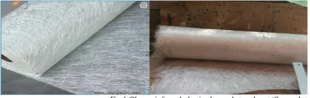
Figure 1 shows the design of glass- fibre-reinforced concrete panels is done based on basic properties like tensile, compressive, bending and shear forces, coupled with estimates of behaviour under secondary loading effects such as creep, thermal response and moisture movements.
Fig.1 Glass reinforced plastic chopped strand mat (Source:http://en.m.wikipedia.org)
Glass-reinforced plastic (GRP) is a composite material or fibre-reinforced plastic made of a plastic reinforced by fine glass fibres.
III. EXPERIMENTALANALYSISFORAXIALLOADING
To test the ultimate load capacity of FRP tube, an experimental study is done with three different specimens, one plain Reinforced concrete cylinder,one with FRP wrapped around plain concrete and other cylinder having same configuration of the primer RC cylinder wrapped with FRP. GFRP covering used here .GFRP mould is made in site using different chemical mixtures like Accelerators, Resin and Bruccine powder withGFRP strand mat.Three specimens were cast in site, of which one RC specimen with 6 numbers of longitudinal reinforcements of 12mm diameter using 3 numbers of 6mm diameter stirrups. Other with plain concrete filled inside the FRP tube and the third specimen with the combination of RC inside FRP tube. The entire specimen has diameter of 200 mm, height of 300mm and thickness of FRP as 3mm. M20 grade concrete is used with nominal mix design.
Test results for axial load testing:
ISSN(Online): 2319-8753 ISSN (Print): 2347-6710
I
nternational
J
ournal of
I
nnovative
R
esearch in
S
cience,
E
ngineering and
T
echnology
(An ISO 3297: 2007 Certified Organization)
Website: www.ijirset.com
Vol. 6, Issue 5, May 2017
Copyright to IJIRSET DOI:10.15680/IJIRSET.2017.0605219 8625 Fig.2 RC column showing crack patterns and CFFT Column showingbuckling effect on axial load test under compressive testing machine.
Results and discussions:
Table 1 shows the ultimate load capacity of each specimens, the table clearly depicts that the presence of FRP doubles the load carrying capacity of column around 47% increase in strength is obtained by the presence of FRP.
In addition to give the confinement property the test result of specimens shows that the GFRP can increase the load carrying capacity of the cylinder as such .Also with addition of GFRP tubes the reinforcement proportion can also be minimized.
Table 1 Ultimate load for different column
CYLINDER DIAMETER(MM) ULTIMATE LOAD (KN)
Plain concrete 200 343
RC 200 430
CFFT 200 820
IV.EFFECTOFIMPACTLOADINGONGFRPWRAPPEDRCCOLUMN
The effect of impact loading over RC column will get increase with increasing thickness of the FRP layers .FRP layer provides confinement throughout the structure and also lateral support to the concrete without bursting out or spalling. This can be studied with increasing the thickness of the sheet providing each time and by varying load criteria Case 1:- Impact loading from a height of 150mm
To do various parametric studies on impact test provide a velocity of 1700mm/s with 2,4,6,8 mm layer thickness and the corresponding displacement of the column is the plotted. The layers will be 1mm thickness, to categorise we take (a) 2mm, (b) 4mm, (c) 6mm and (d) 8mm thick layers of FRP wrapped around the RC column. These models are then made impacted with a sudden load of the hammer.
ISSN(Online): 2319-8753 ISSN (Print): 2347-6710
I
nternational
J
ournal of
I
nnovative
R
esearch in
S
cience,
E
ngineering and
T
echnology
(An ISO 3297: 2007 Certified Organization)
Website: www.ijirset.com
Vol. 6, Issue 5, May 2017
Copyright to IJIRSET DOI:10.15680/IJIRSET.2017.0605219 8626
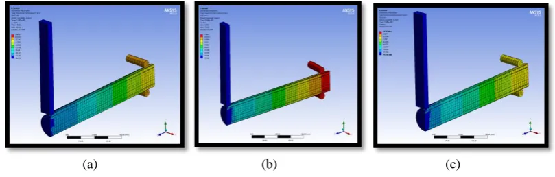
(d)
Fig.3 Directional deformation for(a)2mm (b)4mm(c)6mm and(d)8mm layered CFFT for a velocity of 1700mm/s
The variation of displacement with time graph when the velocity is 1700mm/s acts on 2mm,4mm,6mm and 8mm thick layers on RC .The result can be taken out from the graph as shown in table 2
Table2 Relative displacement variation
V. EFFECTOFCYCLICLOADINGONGFRPWRAPPEDRCCOLUMN
The columns will act differently under cyclic loading condition. Seismic analysis is done like a cyclic load varying time intervals, the input data is given .The support is made fixed to solid block to provide firm seismic loading . Hence this will show lateral displacement to and fro in x – direction. Figure 4 shows the deformation diagram of cyclic loading on CFFT structure.
Fig.4 Deformation diagram for cyclic loading
The same study is made done with all other cases hence plot lateral loading with deformation graph to obtain the peak point of deformation for each case. Figure 5 Shows the Peak deformation for cyclic loading with increasing layer of FRP .The graph shows with increasing lamination for cyclic loading displacement also get restricted.
CASE Layers % variation
Case 1 V=1700mm/s
2-4 44
4-6 56.1
6-8 20.9
Case 2 V=3160mm/s
2-4 23
4-6 33
6-8 31
Case 3 V=4160mm/s
2-4 44
4-6 21
ISSN(Online): 2319-8753 ISSN (Print): 2347-6710
I
nternational
J
ournal of
I
nnovative
R
esearch in
S
cience,
E
ngineering and
T
echnology
(An ISO 3297: 2007 Certified Organization)
Website: www.ijirset.com
Vol. 6, Issue 5, May 2017
Copyright to IJIRSET DOI:10.15680/IJIRSET.2017.0605219 8627 Fig.5 Peak deformation for cyclic loading with increasing layer of FRP
VI. CONCLUSION
On conducting axial load testing on RC, CFFT and Plain concrete with FRP wrapping using compressive testing machine ,the specimen with both FRP wrapping and perfect reinforcement shows good strength and robustness. Also the study concludes the percentage of reinforcement can also minimized by introducing FRP layers over the conventional ones.
Impact loading is done for RC columns and with increasing layer thickness by 2mm each time. The variation in displacement indicates that the efficiency of the structure is improved with each layer.The percentage variation in displacement is observed as 44%, 33%, 20% with increasing layer thickness.
Behavior of both conventional column and RC column for cyclic loading conditions is studied. And it is observed that the peak deformation curve shows a slight variation with 6mm and 8mm FRP wrapped column. The percentage variation in load bearing capacity with increasing layer thickness over on RC column is observed as 62%,17%, 5% , 9% and the corresponding variation in displacement is like 6%,0.8%,0.7%,0.6%.
REFERENCES
[1] AASHTO. (2011). Guide specifications for LRFD seismic bridge design, 2nd Ed.Washington, DC. [2] AASHTO. (2012a). LRFD bridge design specifications, 6th Ed.Washington DC.
[3] AASHTO. (2012b). LRFD guide specifications for design of concrete filled FRP tubes for flexural and axial members, Washington, DC. [4] Alipour, A., Shafei, B., and Shinozuka, M. (2011). “Performance evaluation of deteriorating highway bridges located in high seismic areas.”
J. Bridge Eng.,(ASCE)
[5] Bisby, L. A, Kodur, V. K. R, and Green, M. F. (2005). “Fire endurance of fiber-reinforced polymer-confined concrete columns.” ACI Struct. J.,102(6), 883–891
[6] Choe, D. E, Gardoni, P, Rosowsky, D, and Haukaas, T. (2008). “Probailistic capacity models and sesimic fragility estimates for RC columns subjected to corrosion.” Reliabil. Eng. Syst. Safety
[7] Choe, D. E, Gardoni, P, Rosowsky, D., and Haukaas, T. (2009). “Seismic fragility estimates for reinforced concrete bridges subject to corrosion.”Struct. Safety.
[8] CSA (Canadian Standards Association). (2004a). “Compressive strength of cylindrical concrete specimens.” A23.2-9 C, Mississauga, ON, Canada
[9] Fam, A. (2000). “Concrete-filled fiber-reinforced polymer tubes for axial and flexural structural members.” Ph.D. dissertation, Univ. of Manitoba, Winnipeg, MB
[10] Fam, A., Flisak, B, and Rizkalla, S. (2003). “Experimental and analytical modeling of concrete-filled fiber-reinforced polymer tubes subjected to combined bending and axial loads.” ACI Struct. JPersons” ,
[11] Fujikake, K, Li, B, and Soeun, S. (2009). “Impact response of reinforced concrete beam and its analytical evaluation.” J. Struct. Eng [12] Lin Hai Han, Rui Wang,(2013)high-strength concrete filled steel tubes under transverse impact loading.”
-400 -300 -200 -100 0 100 200 300 400
-100 -50 0 50 100