Available online: http://edupediapublications.org/journals/index.php/IJR/ P a g e | 1408
Web based Traffic controller using GSM and GPS
S Arshad Mehtaj1 & K.Rama Krishna2
1
M-Tech Dept of ECE, Geethanjali Engineering College NANNUR-V, KURNOOL-DIST
Mail Id :- [email protected]
2
Associate ProfessorDept ECE, Geethanjali Engineering College NANNUR-V, KURNOOL-DIST
Mail Id:- [email protected]
Abstract
Intelligent traffic control systems are advanced applications which, without embodying intelligence as
such, aim to provide innovative services relating to different modes of transport and traffic management
and enable various users to be better informed and make safer, more coordinated, and 'smarter' use of
transport networks. In this project, I attempt to make an intelligent system which helps in congestion
control, ambulance clearance and stolen vehicle detection which solves the road safety problems to a
greater extend. Each individual vehicle is equipped with special radio frequency identification (RFID)
tag. We use RFID readers along with microcontrollers to read the tags attached to each vehicle. It counts
the number of vehicles that pass through the path during a specific duration, so that network congestion
is determined and hence green light duration for a particular path. If RFID tag belongs to the stolen
vehicle, it is informed to the police control room through GSM. In addition if the ambulance is
approaching the junction, it will communicate to the traffic controller on the junction to turn the green
light on. This module uses ZIGBEE and PIC microcontroller for wireless communication between
ambulance and the traffic controller.
Keywords:Embedded Technologies, RFID, GSM and GPS.
1.
Introduction
In our daily life we are facing a lot of problems;
main thing is traffic congestion which become
more serious day after day. It is said that high
tome of vehicles, the scanty infrastructure and
the irrational distribution of the development are
the main reasons for augmented traffic jam. The
major cause leading to traffic jam is the large
number of vehicles which is caused by the most
population and the development of economy.
India is the second most populous country in the
world and is a fast growing economy. It is
seeing terrible road congestion problems in its
cities. Infrastructure growth is slow as compared
to the growth in number of vehicles, due to
Available online: http://edupediapublications.org/journals/index.php/IJR/ P a g e | 1409 non lane based and chaotic. It needs a traffic
control solutions, which are different from the
developed Countries. To unravel this problem,
government should encourage people to use
public transport or make use of vehicles with
small size as bicycles or make tax on personal
vehicles. Particularly in some Asian countries
like Vietnam, the local authorities passed a law
limiting the number of vehicles for each family.
The methods mentioned above is really efficient
in the fact that inadequate infrastructure cannot
handle the issue of traffic congestion. The
public conveyance is available and its quality is
very bad, mostly in the establishing countries.
Besides, the highway and roads are incapable of
meeting the requirement of increasing number
of vehicles. Instead of working on the roads to
accommodate for the growing traffic,various
techniques have been devised to control the
traffic on roads like embedded controllers that
areinstalled at the junction.
2.
Related Work
2.1 Existing system:
A.MANUAL CONTROLLING
Manual controlling the name instance it require
man power to control the traffic. Depending on
the countries and states the traffic polices are
allotted for a required area or city to control
traffic. The traffic polices will carry sign board,
sign light and whistle to control the traffic. They
will be instructed to wear specific uniforms in
order to control the traffic.
B.AUTOMATIC CONTROLLING
Automatic traffic light is controlled by timers
and electrical sensors. In traffic light each phase
a constant numerical value loaded in the timer.
The lights are automatically getting ON and
OFF depending on the timer value changes.
While using electrical sensors it will capture the
availability of the vehicle and signals on each
phase, depending on the signal the lights
automatically switch ON and OFF.
2.2 Proposed System
A. Intelligent Traffic Control
Intelligent management of traffic flows can
reduce the negative impact of congestion. In
recent years, wireless networks are widely used
in the road transport as they provide more cost
effective options. Technologies like ZigBee,
RFID and GSM can be used in traffic control to
provide cost effective solutions. FID is a
wireless technology that uses radio frequency
electromagnetic energy to carry information
between the RFID tag and RFID reader. Some
RFID systems will only work within the range
inches or centimeters, while others may work
for 100 meters (300 feet) or more. A GSM
modem is a specialized type of modem, which
accepts a SIM card and operates over a
subscription to a mobile operator, just like a
Available online: http://edupediapublications.org/journals/index.php/IJR/ P a g e | 1410 control modems. These commands come from
Hayes commands that were used by the Hayes
smart modems. The ZigBee operates at
low-power and can be used at all the levels of work
configurations to perform predefined tasks. It
operates in ISM bands (868 MHz in Europe,
915 MHz in USA and Australia, 2.4 GHz in rest
of the world). Data transmission rates vary from
20 Kilobits/second in the 868 MHz frequency
band to 250 Kilobits/second in the 2.4 GHz
frequency band. The ZigBee uses 11 channels in
case of 868/915 MHz radio frequency and 16
channels in case of 2.4 GHz radio frequency. It
also uses 2 channel configurations, CSMA/CA
and slotted CSMA/CA.
B. Stolen Vehicle Detection System.
In this module, for testing purpose, we compare
the unique RFID tag read by the RFID reader
tothe stolen RFIDs stored in the system. If a
match is found, then the traffic signal is
immediately turned to red for duration of 30
seconds. Also an SMS is sent specifying the
RFID number by using SIM300 GSM module.
The LCD display will indicate that stolen
vehicle is present. Here, a GSM modem is
connected with the microcontroller. This allows
the computer to use the GSM modem to
communicate over the mobile network. These
GSM modems are most frequently used to
provide mobile Internet connectivity, many of
them can also be used for sending and receiving
SMS and MMS messages. GSM modem must
support an “extended AT command set” for
sending/receiving SMS messages. GSM
modems are a cost effective solution for
receiving SMS messages, because the sender is
paying for the message delivery. SIM 300 is
designed for global market & it is a tri-band.
C. Emergency Vehicle Clearance
In this module, there are 2 parts, first part which
is ZigBee transmitter is placed in the emergency
vehicle. When the switch is pressed, it will
transmit the signal. The signal contains unique
id and security code. The transmitter contains
PIC16F877A microcontroller and ZigBee
module. The microcontroller sends the
commands and data to the ZigBee via serial
communication. Second part is the receiver,
which is placed at traffic pole. It also contains
PIC16F877A microcontroller and ZigBee
module. The receiver compares the security
code received to the security code present in its
database. If it matches, then it will turn the
green light on. For testing purpose, we used
short range RFID reader in our prototype. First,
the receiver part is turned on. The red and green
signal will be on for 10 seconds duration and
orange light will be on for 2 seconds duration
one after the other. Secondly, we bring the
RFID of stolen vehicle into the range of RFID
reader. Then the signal will turn to red for
Available online: http://edupediapublications.org/journals/index.php/IJR/ P a g e | 1411 Thirdly, we bring 12 RFIDs into the range of
RFID reader, and then the green light duration
will change to 30 seconds. Fourthly, we bring an
emergency vehicle carrying ZigBee transmitter
into the range of ZigBee receiver, and then the
traffic light will change to green till the receiver
receives the ZigBee signal. In the default
condition, red and green light will set for 10
seconds. The time period will be varied
according to the traffic conditions, stolen
vehicle, and emergency vehicle. The transmitter
part is placed in the ambulance. It transmits
ZigBee signal continuously. The stolen vehicle
RFID number should be updated in the
database. If stolen vehicle is found, then it will
immediately turn on red light in the signal. It
sends immediately a message to authorized
person.
3.
Implementation
A. Radio Frequency Identification
(RFID)
RFID is an acronym for radio frequency
identification. Briefly the RF stand for
“radiofrequency” and ID means “identifier” that
allows an item, for instance a library book, to be
identified, accessed, stored, reprogrammed and
communicated by using radio waves. Radio
Frequency Identification (RFID) is a generic
term for non-contacting technologies that use
radio waves to automatically identify people or
objects. There are several methods of
identification, but the most common is to store a
unique serial number that identifies a person or
object on a microchip that is attached to an
antenna. The combined antenna and microchip
are called an "RFID transponder" or "RFID tag"
and work in combination with an "RFID
reader".
An RFID system consists of a reader and one or
more tags. The reader's antenna is used to
transmit radio frequency (RF) energy. The tag
will then modulate the electromagnetic waves
generated by the reader in order to transmit its
data back to the reader. The reader receives the
modulated waves and converts them into digital
data. There are two major types of tag
technologies. "Passive tags" are tags that do not
contain their own power source or transmitter.
When radio waves from the reader reach the
chip’s antenna, the energy is converted by the
antenna into electricity that can power up the
microchip in the tag. The tag is then able to send
back any information stored on the tag by
reflecting theelectromagnetic waves as
described above. "Active tags" have their own
power source and transmitter.
The power source, usually a battery, is used to
run the microchip's circuitry and to broadcast a
signal to a reader. Due to the fact that passive
tags do not have their own transmitter and must
reflect their signal to the reader, the reading
Available online: http://edupediapublications.org/journals/index.php/IJR/ P a g e | 1412 However, active tags are typically larger, more
expensive, and require occasional service.
Frequency refers to the size of the radio waves
used to communicate between the RFID system
components. Just as you tune your radio to
different frequencies in order to hear different
radio stations, RFID tags and readers must be
tuned to the same frequency in order to
communicate effectively. The read range of a
tag ultimately depends on many factors: the
frequency of RFID system operation, the power
of the reader, environmental conditions,
physical size of the tags antenna and
interference from other RF devices. The Sunrom
RFID Card Reader's antenna was designed with
a RFID operation at a tag read distance of
around 7 cm.
B. Global Position System (GPS)
Global Positioning System (GPS) satellites
broadcast signals from space that GPS receivers,
use to provide three-dimensional location
(latitude, longitude, and altitude) plus precise
time. GPS receivers provides reliable
positioning, navigation, and timing services to
worldwide users on a continuous basis in all
weather, day and night, anywhere on or near the
Earth. The output is serial data of 9600 baud
rate which is standard NMEA 0183 v3.0
protocol offering industry standard data
messages and a command set for easy interface
to mapping software and embedded devices.
The current GPS consists of three major
segments. These are the space segment (SS), a
control segment (CS), and a user segment (US).
C. Global System for Mobile
Communications (GSM)
GSM uses Frequency Division Multiplexing
AND Time Division Multiplexing. FDMA
divides the frequency ranges for GSM, which
are 890- 915, 935-960 and some others that the
book didn't have. Each is divided into 200kHz
wide channels. As far as TDMA goes, each time
slot is 577 micro seconds long, 8 time slices is a
frame, lasting for a grand total of 4.615ms. A
multi frame consists of 51 frames, 51 multi
frames make up a Super frame, and 2048 Super
frames make a Hyper frame which is 2715648
frames. The GSM network can be divided into
three parts to illustrate this, consider figure 1. i)
Mobile station, ii) Base station subsystem and
iii) Network subsystem.
Fig 1: GSM Architecture.
Available online: http://edupediapublications.org/journals/index.php/IJR/ P a g e | 1413 The ARM7TDMI-S is a general purpose 32-bit
microprocessor, which offers high performance
and very low power consumption. The ARM
architecture is based on Reduced Instruction Set
Computer (RISC) principles, and the instruction
set and related decode mechanism are much
simpler than those of micro programmed
Complex Instruction Set Computers (CISC).
This simplicity results in a high instruction
throughput and impressive real-time interrupt
response from a small and cost-effective
processor core. Pipeline techniques are
employed so that all parts of theprocessing and
memory systems can operate continuously.
Typically, while one instruction is being
executed, its successor is being decoded, and a
third instruction is being fetched from memory.
4.
Experimental Work
Fig 2: System Circuited Design-1.
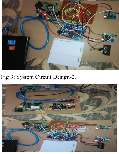
Fig 3: System Circuit Design-2.
Fig 4: System Circuit Design-3.
Fig 5: System Circuit Design-4.
5.
Conclusion
With automatic traffic signal control based on
the traffic density in the route, the manual effort
on the part of the traffic policeman is saved. As
the entire system is automated, it requires very
Available online: http://edupediapublications.org/journals/index.php/IJR/ P a g e | 1414 detection, the signal automatically turns to red,
so that the police officer can take appropriate
action, if he/she is present at the junction. Also
SMS will be sent so that they can prepare to
catch the stolen vehicle at the next possible
junctions. Emergency vehicles like ambulance,
fire trucks, need to reach their destinations at the
earliest. If they spend a lot of time in traffic
jams, precious lives of many people may be in
danger. With emergency vehicle clearance, the
traffic signal turns to green as long as the
emergency vehicle is waiting in the traffic
junction. The signal turns to red, only after the
emergency vehicle passes through. Further
enhancements can be done to the prototype by
testing it with longer range RFID readers. Also
GPS can be placed into the stolen vehicle
detection module, so that the exact location of
stolen vehicle is known. Currently, we have
implemented system by considering one road of
the traffic junction. It can be improved by
extending to all the roads in a multi-road
junction.
6. References
[1] Venkatesh.H,Shrivastsa D perur,Jagadish M
C, ”An approach to make way for intelligent
ambulance using
IoT,”Int.jour.ofElec.andElectr.Research ISSN
Vol.3,Issue 1,pp(218- 223)jan=mar2015
[2] S.Saravanan, PillutlaHarikrishna, ”Big data
exchange between ambulance bus to hospital
network through internet in telemedicine using
computer communication network and 3G
mobile antenna,”Int. conf .on comp. comm.and
Informatics,Jan08-10,2015
[3] Geetha.E,V.Viswanadha,Kavitha.G,”Design
of an intelligent auto traffic signal controller
with emergency
override,”Int.Jour.ofEng.science and
Inno.tech.(IJESIT),vol.3,issue.4,July 2014
[4] V.Bali.Reddy and
A.Suvarnamma,”Implementation of green wave
system for vehicles,”(IJERST)2014
[5] A. K. Mittal and D. Bhandari, “A novel
approach to implement green wave system and
detection of stole vehicles,” in Proc. IEEE 3rd
Int. Adv. Comput., Feb. 2013, pp. 1055–1059.
[6] S.Sharma,A.Pithora,G.Gupta,M.Goel and
M.Sinha,”Traffic light priority control for
emergency vehicle using RFID, ”Int. J. Adv.
Elec. Elect. Eng., vol.2,no.3 ,pp.363-366, 2013
[7] R.Hedge,R.R.Sali, and M.S.Indira,”RFID
and GPS based automatic lane clearancesystem
for
ambulance”,Int.J.Adv.Elec.Elect.Eng.,vol.2,no.
3,pp.102-107,2013
[8]
P.Sreelekha,D.VishnuVardhan,”Implementing
of green wave system for traffic clearance of
emergency vehicles and for detection of theft
Available online: http://edupediapublications.org/journals/index.php/IJR/ P a g e | 1415
[9] W.Viriyasitavat and
Ozan.K.Tonguz,”Priority managemant of
emergency vehicles at intersections using
self-organized traffic control,”ieee journal 2012
[10] A.Shuib,A.Zaharudin,”TAZ-OPT:A goal
programming model for ambulance location and
allocation,”IEEEcolloqulum on
hum,sci,andeng.research(CHUSER 2011),Dec
5-6 2011,Penang
[11] M. Abdoos, N. Mozayani, and A. L. C.
Bazzan, “Traffic light control in non-stationary
environments based on multi agent Q-learning,”
in Proc. 14th Int. IEEE Conf. IntellTransp.
Syst., Oct. 2011, pp. 580–1585.
[13] B. P. Gokulan and D. Srinivasan,
“Distributed geometric fuzzy multiagent urban
traffic signal control,” IEEE Trans. Intell.
Transp. Syst., vol. 11, no. 3, pp. 714–727, Sep.
2010.
[14] ShahriarKhan,”Automated versus human
traffic control for Dhaka and cities in
developing nations,”IEEE 2007
[15] DiptiSreenivasan,MinChee Choy, and Ruey
Long Cheu”Neural networks for real time traffic
signal control,”IEEE Trans. . Intell. Transp.