Fuzzy Logic controller Based Adaptive D
@
Link Voltage Control
For Common Point Interface Voltage Variations in a 3- Phase Grid
Tied SPV system
fH�.Sai Sruthi8 N Gangadharff
f
PG scholar ,
ffAssociate professor�
&�
H.O.D
Department of EEE GATES Institute of Technology, Gooty, Andhrapradesh, India
ABSTRACT:
This proposed model deals with a three-phase
two-stage grid tied SPV (solar photo-voltaic) system. The first stage is a boost converter, which serves the purpose of MPPT (maximum power point tracking) and feeding the extracted solar energy to the DC link of the PV inverter, whereas the second stage is a two-level VSC (voltage source converter) serving as PV inverter which feeds power from a boost converter into the grid. The versatile DC voltage control helps in the
decrease switching power losses. The dc voltage
is regulated using a PI controller when various
control algorithms are used for load
compensation. In this work, a fuzzy logic based supervisory method is proposed to improve transient performance of the dc link. The fuzzy logic based supervisor varies the proportional and integral gains of the PI controller during the transient period immediately after a load change. A considerable reduction in the error in dc link voltage during load change compared to a
normal PI controller is obtained. The
performance of the proposed strategy is proved using detailed simulation studies.
Index Terms—Adaptive DC link, MPPT, overvoltage, solar PV, two-stage, three phase, under voltage.
1. INTRODUCTION
T HE electrical energy has a vital role in development of human race in the last century. The diminishing conventional primary sources for electricity production have posed an energy
scarcity condition in front of the world. The renewable energy sources such as solar, wind, tidal etc are few of such options which solve the problem of energy scarcity. The cost effectiveness of any technology is prime factor for its commercial success. The SPV (Solar Photovoltaic) systems have been proposed long back but the costs of solar panels have hindered the technology for long time, however the SPV systems are reaching grid parity [1], [2].
The solar energy based systems can be classified into standalone and grid interfaced systems. The energy storage (conventionally batteries) management is the key component of standalone system. Various problems related to battery energy storage standalone solar energy conversion systems are discussed in [3]–[6]. Considering the problems associated with energy storage systems, the grid interfaced systems are more preferable, in case the grid is present. The grid acts as an energy buffer, and all the generated power can be fed into the grid. Several grid interfaced SPV systems are proposed in past addressing various issues related to islanding, intermittency, modeling etc .
solar, modularity of power converter and static energy conversion process. The initial investment in SPV systems is high because of high cost of solar panels [3]. Therefore, considering the initial investments for any installed plant, the aim is to extract maximum energy output from the given capacity
To accomplish the objective of extraction of maximum energy from an installed PV array several techniques are proposed in the literature [4]–[8]. A review of MPPT (Maximum Power Point Tracking) techniques is shown in [4]. An incremental conductance (InC) based MPPT technique is shown in [5]. An ANN based MPPT algorithm is shown in [6]. The application of sliding mode controller to MPPT algorithm is shown in [7]. A combination of fractional open circuit voltage and fuzzy based MPPT technique is shown in [8] wherein a constant offset is added at the output of fuzzy controller to improve the
MPPT performance. The incremental
conductance based MPPT is fast, accurate and easy to implement. In this paper, a composite InC based MPPT method is used. The composite InC method is a combination of fractional Voc and InC based method. The proposed MPPT technique limits the area of search for MPP point hence improves the MPPT performance.
The tripping of the plant causes generation loss in case of grid tied PV generation system. In general, grid tied VSCs have under voltage and overvoltage protection. The nominal range of set point for under voltage and over voltage is around 0.9 pu and 1.1 pu [9]. This range is very narrow because of reasons such as converter may lose control, increase in converter rating, and converter losses at low voltage etc. In case of weak distribution system, a wide voltage variation is observed. During peak loading condition, a sustained voltage dip or under voltage is observed commonly. The practical range of voltage variation is about ±15% of the
nominal voltage. Normally in such wide variation of distribution system the shunt connected converter trips frequently. However, in case of tripping of converter the PV generation is lost even when PV power is available. Therefore, minimizing converter trips indirectly increases energy yield from the installed plant. The proposed system is capable of working with wide range of voltage variation hence avoids the generation loss.
The use of two stage SPV generation system has been proposed by several researchers. Conventionally a DC-DC converter is used as first stage which serves the purpose of MPPT. The duty ratio of DC-DC converter is so adjusted that PV array operates at MPP point. The second stage is a grid tied VSC (Voltage Source Converter) which feeds the power into the distribution system. A single phase two stage grid tied PV generation system with constant DC link voltage is shown in [2]. Moreover, the three phase grid tied PV generation system with constant DC link voltage control is also shown. The concept of loss reduction by adaptive DC link voltage for VSC in hybrid filters is shown in [4] wherein, the DC link voltage is adjusted according to reactive power requirement of filter. However, in the proposed system the DC link voltage of VSC is made adaptive with respect to CPI voltage variation. Moreover, the circuit topologies in both the systems are different. Therefore, the work presented in [3], [4] is very different from the proposed work.
the system always operates at a DC link voltage corresponding to worst case condition.
In this paper, a simple control scheme is presented for grid interfaced PV system with adaptive DC link voltage structure for CPI voltage variation. A boost converter is used as the first stage and a two level VSC is used as the second stage. Unlike the earlier work with constant DC link voltage for VSC, the presented work proposes an adaptive DC link voltage structure for the VSC and associated benefits. The adaptive DC link voltage mainly reduces switching losses in all power devices and high frequency ohmic losses in the interfacing inductor. The maximum benefit of proposed DC link voltage structure is found not only during under voltage (common in far radial ends) but also under nominal grid voltage condition as the DC link voltage is kept just necessary for proper current control not according to worst case scenario. The claimed benefits of the system are verified experimentally along with comparison with conventional system. Moreover, the feed-forward term for PV contribution is included to improve the dynamic response. The PV feed forward term includes the effect of both CPI voltage variation and PV power variation. A linearised model of DC link voltage control and effect of PV feed forward component on the same is also analyzed in this paper. In the proposed system both the input and output voltages of DC-DC boost converter are adjusted in real time while keeping the objective of MPPT intact. The performance of proposed control algorithm is satisfactory under insolation change and sudden variation of CPI voltage.
The two stage grid interfaced three phase systems are proposed by several researchers, however, none of them have
Fig 1 system configuration
Shown performance for such wide range of CPI voltage variations (350 V to 480 V for nominal of 415 V). The operation of the system for a wide range of CPI voltage variation increases the rating of the VSC and further the cost. However, small increment in the cost of VSC can be justified on account of large initial investment on PV array. The THD of grid current and voltages has been found well under IEEE-519 standard (less than 5%) under all operating conditions [26]. Moreover, it should be noted that none of the ratings of the power devices are compromised in the proposed system as compared to conventional system, as in both the cases the ratings are decided based on worst case scenario. Therefore, the system with proposed control approach yields more energy output with the same hardware resources.
II. SYSTEM CONFIGURATION
of VSC are connected to interfacing inductors and the other end of interfacing inductors are connected to CPI. A ripple filter is also connected at CPI to absorb high frequency switching ripples generated by the VSC. The values of various components and parameters used in simulation and experimentation are given in Appendix A.
III. CONTROL APPROACH
The basic control approach for the SPV system is shown in Fig. 2. The control of the system can be divided into two main parts, which are control of the boost converter and control of a grid tied VSC. The input voltage of a boost converter is adjusted according to MPPT algorithm and the output voltage of boost converter, which is also the DC link voltage of VSC is also kept adaptive according to CPI voltage condition. In overall, the proposed system is operated such that both the input and output voltages of boost converter are adjusted according to Sensed variables of the circuit.
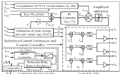
Fig 2 Block diagram of control approach
The boost converter feeds the power to the DC link of VSC, which then feeds that power into the three-phase grid at unity power factor with respect to CPI. A composite InC based MPPT technique is used to estimate the reference PV array voltage and a PLL-less control is proposed for the control of the VSC. The amplitude of the refrence grid currents is estimated using a PV feedforward (PVFF) term and a PI controller DC
link voltage error. A set of unit vectors is estimated from grid voltages to synchronize output currents of VSC. The estimated reference grid currents are compared with sensed grid currents and a hysteresis current controller is used to generate switching logic for VSC. The detailed formulation for control algorithm is presented in the later half of this section.
A. Maximum Power Point Tracking
A composite InC based MPPT algorithm is used. A range of voltage for peak power is known with the knowledge from fractional Voc MPPT, which is 0.7Vocmax to 0.9Vocmax, where Voc is open circuit voltage and Vocmax is maximum open circuit voltage. The voltage for peak power is always searched in this range for fast search of Vmpp. The InC algorithm works in order to minimize the difference between the incremental conductance and the conductance offered by the PV array. At first, the reference PV array voltage is estimated based on the InC principle then that reference voltage is used to estimate the duty ratio of the boost converter. For calculation of an incremental conductance ΔIP V and ΔVP V are estimated as,
where IPV(k) and VPV(k) are the instantaneous sampled current and voltage of the solar array. The governing equations for InC based MPPT algorithm is as,
search in a limited region, the VP V ref is bounded by corresponding upper and lower saturation values (0.7Vocmaxto 0.9Vocmax). The output of that saturation block is designated as new PV array voltage (VP V refn), which is then used for estimation of reference duty ration. The reference PV voltage (VP V refn) and sensed DC link voltage (VDC ) are then used to estimate the duty ratio for the boost converter. The governing equation for estimating duty ratio is as,
This reference duty ratio is compared with saw-tooth waveform to generate switching logic for the boost converter.
B. Control Algorithm for VSC
The control approach for VSC is demonstrated in Fig. 2. The main objective of the control algorithm for VSC is to regulate the DC link voltage to the set reference value and to inject the extracted power from PV array into the grid at unity power factor with respect to CPI. In order to control the output currents of VSC (or grid currents), the appropriate reference grid currents are estimated. At first the amplitude of grid currents is estimated and the estimated amplitude is then multiplied with in-phase unit vectors (synchronization signals) to keep the grid currents balanced and sinusoidal.
For control purpose, the CPI line voltages (vsab and vsbc), DC link voltage (vDC) and grid currents (iga and igb) are sensed. The phase voltages are estimated from the line voltages. The in-phase unit vectors are estimated from the estimated phase voltages. For estimation of unit vectors (za, zb, zc), the phase voltages are divided by amplitude of three phase voltages (Vz). The amplitude of CPI voltage is estimated as,
The unit vectors for all three phases are estimated as,
For proper control of VSC output current, the DC link voltage of VSC should be greater than amplitude of line voltage. Moreover, in order to adaptively adjust the DC link voltage with respect to CPI voltage variation, the reference DC link voltage is adaptively adjusted with amplitude of CPI voltage. The reference DC link voltage is estimated as,
For proper current control the DC link voltage must be higher than the amplitude of CPI line voltage. Therefore, reference DC link voltage is kept around 10% higher than the peak of CPI line voltage, considering the drop across switches, interfacing inductor, resistance of interfacing inductor and proper current control under DC link voltage dynamics. Hence, the selected value of µ in the proposed work is 1.1.
A PV feed forward (PVFF) term for PV array contribution to grid current is also estimated to provide fast dynamic response for changes in solar insolation and grid voltages. The PV feedforward term is estimated as,
It can be observed from the above equation that in case of insolation variation, the PV power (PPV = VPV ∗ IPV) changes and the instantaneous effect can be observed on PV contribution term. Moreover, the in case of voltage variation at CPI, the grid currents need to be adjusted to feed same solar power, which eventually is adjusted due to term Vz in the PV contribution term.
The grid currents are assumed coming out of CPI terminals and considering the direction of grid currents, the losses are drawn from the grid whereas the PVFF is fed into the grid. Therefore, net amplitude of grid current is estimated as,
The estimated amplitude of grid current Irg is then multiplied with unit vectors of corresponding phases to estimate reference grid currents. The reference and sensed grid currents are then given to current controller. The output of current controller is the switching pulses to the VSC.
IV. FUZZY LOGIC
In recent years, the number and variety of applications of fuzzy logic have increased significantly. The applications range from consumer products such as cameras, camcorders, washing machines, and microwave ovens to
industrial process control, medical
instrumentation, decision-support systems, and portfolio selection. To understand why use of
fuzzy logic has grown, you must first understand what is meant by fuzzy logic.
Fig.3 The Primary GUI Tools Of The Fuzzy Logic Toolbox
The FIS Editor handles the high level issues for the system How much input and output variables? What are their names? The Fuzzy Logic Toolbox doesn't limit the number of inputs. However, the number of inputs may be limited by the available memory of our machine. If the number of inputs is too large, or the number of membership functions is too big, then it may also be difficult to analyse the FIS using the other GUI tools. The Membership Function Editor is used to define the shapes of all the membership functions associated with each variable. The Rule Editor is for editing the list of rules that defines the behaviour of the system.
4.1The FIS Editor
Fig.4 The FIS Editor
We will see the diagram updated to reflect the new names of the input and output variables. There is now a new variable in the workspace called tipper that contains all the information about this system.
Fig.5 ‘Save to workspace as...’ window
By saving to the workspace with a new name, we also rename the entire system. Our window will look like as shown in Fig.9.
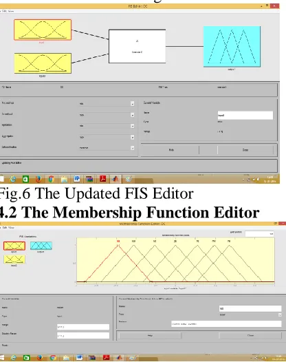
Fig.6 The Updated FIS Editor
4.2 The Membership Function Editor
Fig. 7 The Membership Function Editor
Fig.8 Add MFs… Window
Fig.9 The Updated Membership Function Editor
4.3 The Rule Editor
Fig.10 The Rule Editor
Fig.11 Fuzzy rules
V. SIMULATION RESULTS
stage. And in the second stage, it consists of a three phase inverter which has 6 IGBT’s.
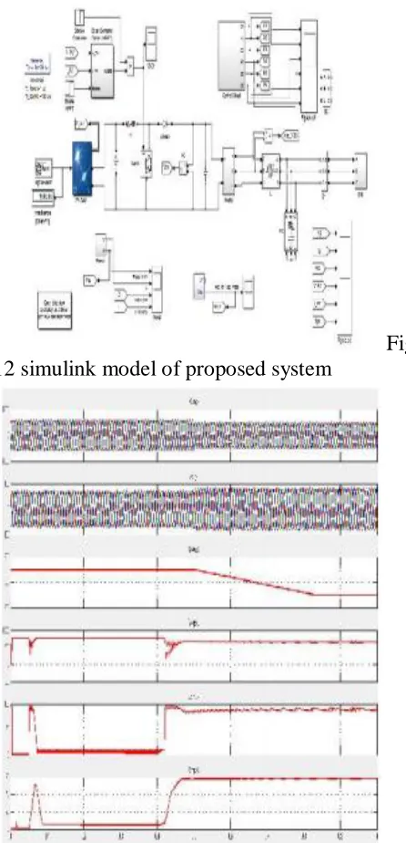
Fig 12 simulink model of proposed system
Fig. 13 Simulated performance for, (a) variations in the grid voltage, (b) variations the grid current, (c) adaptive DC voltage waveform as the voltages variations range upto 15% at CPI, (d),(e),(f) shows the voltage ,current and power waveforms of PV panel.
Fig. 14 Simulated performance for, (a) variations in the grid voltage, (b) variations the grid current, (c) adaptive DC voltage waveform as the voltages variations range upto 20% at CPI, (d),(e),(f) shows the voltage ,current and power waveforms of PV panel
The waveforms show grid voltage and grid current, the adaptive D.C voltage and voltage and current waveforms of PV panel upto 20% voltage variations at CPI while employing FLC with MPP technique at Boost Converter& inverter
VI. CONCLUSION
approaches not only enchances the speed and accuracy of the model , but also improves performance of the system upto 20 % of CPI variations. A PV array feed forward term is used which helps in fast dynamic response. The concept of adaptive DC link voltage has been proposed for grid tied VSC for PV application however, the same concept can be extended for all shunt connected grid interfaced devices such as, STATCOM, D-STATCOM etc. The proposed model yields increased energy output using the same hardware resources just by virtue of difference in DC link voltage control structure. The Fuzzy Logic Control used in this model not only increased the speed of the system but also improved its accuracy. We can further improve the system by using other artificial intelligence techniques. The same can be implemented for more variations at CPI.
APPENDIX
Parameters for simulation: Three-phase grid voltage 415 V, frequency = 50 Hz, supply inductance = 2.42 mH and supply resistance = 0.76 Ω, interfacing inductor = 4 mH, ripple filter R = 5Ω, C = 5 µF, Kp = 1, Ki = 21, PV array open circuit voltage: 500 V, PV array short circuit current: 70 A, PV array peak power: 25 kW, µ = 1.1. Experimental Parameters: Three-phase grid voltage 415 V, frequency = 50 Hz, interfacing inductor = 6 mH, ripple filter R = 5Ω, C = 5 µF, Kp = 1, Ki = 0.1, PV array open circuit voltage: 500 V, PV array short circuit current: 16 A, PV array peak power: 6.5 kW, µ = 1.1.
REFERENCES
[1] M. Pavan and V. Lughi, “Grid parity in the Italian commercial and industrial electricity market,” in Proc. Int. Conf. Clean Elect. Power (ICCEP’13), 2013, pp. 332–335.
[2] M. Delfanti, V. Olivieri, B. Erkut, and G. A. Turturro, “Reaching PV grid parity: LCOE analysis for the Italian framework,” in Proc. 22nd
Int. Conf. Exhib. Elect. Distrib. (CIRED’13), 2013, pp. 1–4.
[3] H. Wang and D. Zhang, “The stand-alone PV generation system with parallel battery charger,” in Proc. Int. Conf. Elect. Control Eng. (ICECE’10), 2010, pp. 4450–4453.
[4] M. Kolhe, “Techno-economic optimum sizing of a stand-alone solar photovoltaic system,” IEEE Trans. Energy Convers., vol. 24, no. 2, pp. 511– 519, Jun. 2009.
[5] D. Debnath and K. Chatterjee, “A two stage solar photovoltaic based stand alone scheme having battery as energy storage element for rural deployment,” IEEE Trans. Ind. Electron., vol. 62, no. 7, pp. 4148–4157, Jul. 2015.
[6] S. Krithiga and N. G. Ammasai Gounden, “Power electronic configuration for the operation of PV system in combined grid-connected and stand-alone modes,” IET Power Electron., vol. 7, no. 3, pp. 640–647, 2014.
[7] I. J. Balaguer-Álvarez and E. I. Ortiz-Rivera, “Survey of distributed generation islanding detection methods,” IEEE Latin Amer. Trans., vol. 8, no. 5, pp. 565–570, Sep. 2010.
[8] C. A. Hill, M. C. Such, D. Chen, J. Gonzalez, and W. M. Grady, “Battery energy storage for enabling integration of distributed solar power generation,” IEEE Trans. Smart Grid, vol. 3, no. 2, pp. 850–857, Jun. 2012.
[9] W. Xiao, F. F. Edwin, G. Spagnuolo, and J. Jatskevich, “Efficient approaches for modeling and simulating photovoltaic power systems,” IEEE J. Photovoltaics, vol. 3, no. 1, pp. 500–508, Jan. 2013.