ISSN 2286-4822 www.euacademic.org
Impact Factor: 3.4546 (UIF) DRJI Value: 5.9 (B+)
Design and Implementation of a Module Radar
System Based on VB.net Language and ultrasonic
waves
AHMED F. ALBAGHDADI Almustaqbal University College Babylon, Iraq AHMED M. OJIEMY Almustaqbal University College Babylon, Iraq
Abstract:
The use of servo motor type in order to build a complete system to know the distance from all directions and angles, saves a lot of cost and accuracy compared with the traditional method of development of sensors in all directions because in this case there must be a lot of points that are difficult for the fixed sensors to monitor simultaneously, while in the proposed system the motor can rotate the sensor at all angles. And get a distance from all directions and all angles.
The proposed system consists of a sender and receiver of ultrasound in addition to the arduino for processing data received from a sensitive ultrasound servo motor using the bulk of the sensitive rotate at all angles and a resolution of up to 180 degrees each half-cycle in addition to the presence of computers in order to display data on the screen using the programming language and displayed in a manner much like radar. It can be concluded that this system can be used in many applications, because it increases accuracy in knowledge of closed and open roads in a radius of 4 meters circle. It has been corrected and the implementation of the system in practice and proved its accuracy and its technology in many of the test.
implementation of the system in practice and proved its accuracy and its technology in many of the tests.
Key words: Ultrasonic, Radar, Servo motor, VB.NET, Arduino UNO.
1- INTRODUCTION
Radar is an object-detection system that uses radio waves to determine the range, angle, or velocity of objects. It can be used to detect aircraft, ships, spacecraft, guided missiles, motor vehicles, weather formations, and terrain. A radar transmits radio waves or microwaves that reflect from any object in their path. A receive radar, which is typically the same system as the transmit radar, receives and processes these reflected waves to determine properties of the object.
Radar was secretly developed by several nations in the period before and during World War II. The term RADAR was coined in 1940 by the United States Navy as an acronym for Radio Detection and Ranging. The term radar has since entered English and other languages as a common noun, losing all capitalization.
visible, or near infrared light from lasers rather than radio waves.
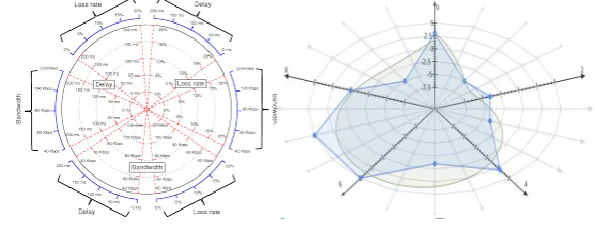
A radar chart is a graphical method of displaying multivariate data in the form of a two-dimensional chart of three or more quantitative variables represented on axes starting from the same point. The relative position and angle of the axes is typically uninformative.
Figure 1 Radar Chart
Radar charts are a useful way to display multivariate observations with an arbitrary number of variables. Each star represents a single observation. Typically, radar charts are generated in a multi-plot format with many stars on each page and each star representing one observation. The star plot was first used by Georg von Mayr in 1877. Radar charts differ from glyph plots in that all variables are used to construct the plotted star figure. There is no separation into foreground and background variables. Instead, the star-shaped figures are usually arranged in a rectangular array on the page. It is somewhat easier to see patterns in the data if the observations are arranged in some non-arbitrary order (if the variables are assigned to the rays of the star in some meaningful order).
2- RADAR EQUATION
where
Pt = transmitter power
Gt = gain of the transmitting antenna
Ar = effective aperture (area) of the receiving antenna; this can also be expressed as , where
= transmitted wavelength Gr = gain of receiving antenna
σ = radar cross section, or scattering coefficient, of the target F = pattern propagation factor
Rt = distance from the transmitter to the target Rr = distance from the target to the receiver.
In the common case where the transmitter and the receiver are at the same location, Rt = Rr and the term Rt² Rr² can be replaced by R4, where R is the range. This yields:
This shows that the received power declines as the fourth power of the range, which means that the received power from distant targets is relatively very small. Additional filtering and pulse integration modifies the radar equation slightly for pulse-Doppler radar performance, which can be used to increase detection range and reduce transmit power.
The equation above with F = 1 is a simplification for transmission in a vacuum without interference. The propagation factor accounts for the effects of multipath and shadowing and depends on the details of the environment. In a real-world situation, path loss effects should also be considered.
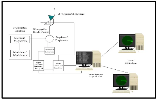
A transmitter that generates the radio signal with an oscillator such as a klystron or a magnetron and controls its duration by a modulator.
A waveguide that links the transmitter and the antenna.
A duplexer that serves as a switch between the antenna and the transmitter or the receiver for the signal when the antenna is used in both situations. A receiver. Knowing the shape of the desired received signal (a pulse), an optimal receiver can be designed using a matched filter.
A display processor to produce signals for human readable output devices.
An electronic section that controls all those devices and the antenna to perform the radar scan ordered by software.
Figure 2 Radar System
4- PROCESSOR (MCU)
is the Atmel MCU (ATmega328), we used the Arduino platform that contains the ATmega328 MCU and this platform is the open source platform which is easy to use in terms of software and hardware see Figure bellow. The most important specifications of the MCU are.
Digital I/O 14 Pin
Analog Input 6 Pin (10-bits ADC) DC Current per I/O 40 mA Flash Memory 32 KB (ATmega328) Clock Speed 16 MHz
MCU is programmed through the Arduino programming language which is integrated development environment (IDE). This language based on C / C + + language. We programmed the MCU to control the unit tasks receives data from the serial port of the computer, processing and sending orders to relay shield for the purpose of control of the gate.
Figure 3 Atmel MCU (ATmega328) and the Arduino pin out
5- PROPOSED SYSTEM
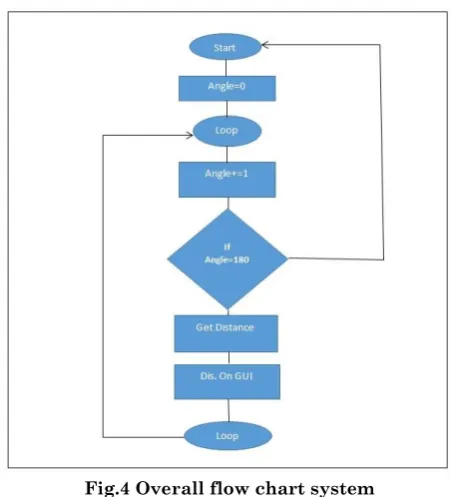
in the graphical user interface of the system in base station as appoint in scale.
Fig.4 Overall flow chart system
Firstly, we have been connect the arduino plat form to the pins shows in the figure below.
Fig. 5 Pins connection
Fig.6 Ultrasonic connection to arduino platform
Then we have built and programmed Graphical User Interface (GUI) using visual basic language or (VB.NET) to reading range of the proposed radar and to detect any body and appear it in the graphical user interface of the system in base station.
Fig.41 Graphical User Interface (GUI)
REFERENCES
[1] Moerland, T., “Steganography and Steganalysis”, Leiden Institute of Advanced Computing Science.
[3] Wang, H & Wang, S, “Cyber warfare: Steganography vs. Steganalysis”, Communications of the ACM, 47:10, October 2004
[4] Debiprasad Bandyopadhyay, Kousik Dasgupta, J. K. Mandal, Paramartha Dutta, "A Novel Secure Image Steganography Method Based On Chaos Theory In Spatial Domain" International Journal of Security, Privacy and Trust Management (IJSPTM) Vol 3, No 1, February 2014
[5] Chandramouli, R., Kharrazi, M. & Memon, N., “Image steganography and steganalysis: Concepts and Practice”, Proceedings of the 2nd International Workshop on Digital Watermarking, October 2003
[6] Anderson, R.J. & Petitcolas, F.A.P., “On the limits of steganography”, IEEE Journal of selected Areas in Communications, May 1998
[7] Currie, D.L. & Irvine, C.E., “Surmounting the effects of lossy compression on Steganography”, 19th National Information Systems Security Conference, 1996
[8] Johnson, N.F. & Jajodia, S., “Exploring Steganography: Seeing the Unseen”, Computer Journal, February 1998
[9] “Reference guide: Graphics Technical Options and Decisions”