High Speed 2-D DWT using Modified
Distributed Arithmetic and Brent Kung Adder
Technique
Asmita Gupta, Prof. Rahul Shrivastava, Dr. Paresh Rawat
M. Tech. Scholar, Department of EC, SISTec, Gandhi Nagar, Bhopal, India
Assistant Professor, Department of EC, SISTec, Gandhi Nagar, Bhopal, India
Head of Dept, Department of EC, SISTec, Gandhi Nagar, Bhopal, India
ABSTRACT: The DWT is expressed in a generalized form know as discrete wavelet transform which analyzes both
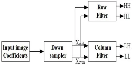
the low and high sub bands with equal priority at every decomposition level. The DWT is a mathematical technique that provides a new method for signal processing. Due to various useful features like adaptive time-frequency window, lower aliasing distortion and efficient computational complexity, it is widely used in many signal and image processing applications. 2-D DWT is widely used in image and video compression. But flipping scheme introduces some design complexities in selected DWT structures.
So in our proposed work, we have implemented BK adder and MDA technique that provides multiplier-less implementation and also will work for every bit.
The proposed MDA and BK adder based 1-D and 2-D DWT algorithm shows good performance as compared to previous algorithm. The proposed architecture for DWT implementation reduces the chip area, less computation time and also minimizes the maximum combinational path delay.
KEYWORDS: 2-D DWT, MDA, Low-pass Sub-band (LPSB), High-pass Sub-band (HPSB), VHDL Simulation
I.INTRODUCTION
The Multi-Resolution Analysis (MRA) ability and time-scale region qualities of the DWT have built up it as a ground-breaking apparatus for various applications, for example, flag examination, picture pressure and numerical investigation, as expressed by Mallat (1989). This has driven various research gatherings to create calculations and equipment models to execute the DWT. DWTs are as a rule progressively utilized for picture coding. This is because of the way that the DWT bolsters highlights, similar to dynamic picture transmission, simplicity of compacted picture control, district of enthusiasm coding [1].
The intrinsic points of interest of the Discrete Wavelet Transform over different changes, similar to the DCT, DST and DHT make it reasonable for JPEG2000 pressure norms [2]. The multiresolution highlight of the wavelets defeats the blocking antiques issues in the DCT [3]. The convolutional DWT utilizes Finite Impulse Response (FIR) channel banks for actualizing sub-band deterioration. This requires higher computational many-sided quality and equipment, making it unacceptable for ongoing picture/video handling applications.
In the customary convolution technique for DWT, a couple of FIR is connected in parallel, to determine HPSB and LPSB coefficients. The models are for the most part collapsed, and can be comprehensively grouped into serial and parallel structures as talked about [4].
and a closest neighbor correspondence are urgent for acknowledgment of superior VLSI framework [6]. Keeping this in see, unreasonable execution utility particular VLSI structures are hurriedly advancing lately. The extraordinary reason VLSI frameworks augment handling simultaneousness by parallel/pipeline preparing and gives financially savvy other option to ongoing application. Subsequently, 2-D DWT is at present done in a VLSI framework to meet the worldly prerequisite of ongoing application. Keeping up this reality in see, various format plans have been forewarned inside the last a very long time for proficient usage of 2-D DWT in a VLSI framework. Analysts have embraced distinctive calculation definition, mapping plan, and compositional outline techniques to decrease the computational time, number juggling many-sided quality or memory multifaceted nature of 2-D DWT structures. Nonetheless, the territory defers execution of the current structures changes barely.
II.DISCRETEWAVELETTRANSFORM
The LL sub-band speaks to a guess of the first picture; the LPSB can be selected at fourth part of image. This procedure is rehashed for the same number of levels of disintegration as wanted. JPEG2000 format indicates four parts of disintegration, as talked about in, albeit three are typically viewed as worthy in equipment. With a specific end goal to stretch out the 1-D channel to register 2-D DWT in JPEG2000, two focuses must be considered [7].
(
)
(
)
1(
2
)
1
0
i
n
Y
i
h
n
Y
ljk i j
l
(1)
(
)
(
)
1(
2
)
1
0
i
n
Y
i
g
n
Y
hjk i j
h
(2)Furthermore, impermanent outcomes should be put away, which are produced by the 2-D segment channel. The measure of the outer memory get to, and the territory possessed by the implanted interior cradle, are viewed as the most basic issues for the execution of the 2-D-DWT. Be that as it may, the interior cushion would possess a vast zone and expend a lot of intensity. In the divisible strategy, the coveted channel coefficients at each level are subject to the past yield level, and this presents postponement or dormancy in DWT decay.
III.PROPOSEDARCHITECTURE
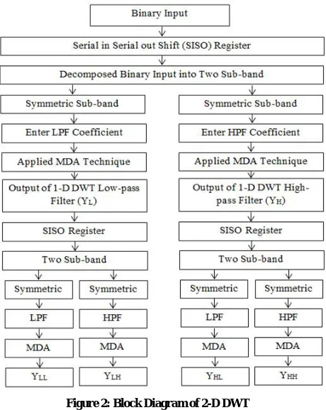
The flow chart of proposed algorithm is shown in figure 2. In this stream graph, the double information is connected to the serial in serial out register. All whole numbers connected to the twofold frame in DWT design. Parallel information
is relying upon the word length i.e. assume word length of the twofold info (3 down to 0) implies the information go is 0 to 15.
If takes the LPS coefficients h0, h1, h2, h3, and h4 multiply by u1, u2, u3, u4 and u5 then multiplier-less 1-D DWT LPS
output is
5 4 3 2 1 4 3 2 1 0u
u
u
u
u
h
h
h
h
h
Y
LPS Where, ) 8 ( ) (1 X n X n
u ) 7 ( ) 1 (
2 X n X n
u
)
6
(
)
2
(
3
X
n
X
n
u
) 5 ( ) 3 (4 X n X n
u
)
4
(
5
X
n
u
5 4 3 2 13
2
10
34
77
u
u
u
u
u
Y
LPS So,All the LPS coefficient arranges down to up is below:
5 4 3 2 10
1
1
0
0
0
1
1
0
1
0
1
1
1
0
0
1
1
0
0
0
1
0
0
1
0
1
1
0
1
1
1
1
1
0
1
0
0
0
1
u
u
u
u
u
Y
HAll rows pass through look up table and replace LPS coefficient to input
Let u1 = 4, u2 = 4, u3 = 4 u4 = 4 and u5 = 2 and put above equation and last row value is represented by 2’s complement
value
Then
K1 = u1 + u5 = 0110, K2 = u2 + u3 + u4 + u5 = 1110, K3 = u1 + u3 + u4 = 1100, K4 = u1 + u4 = 1000, K5 = u3 + u4 = 1000,
All K1toK8 value passed through sign extension block then
K1 = u1 = 00110, K2 = u2 + u3 + u4 + u5 = 01110, K3 = u1 + u3 + u4 = 01100,
K4 = u1 + u4 = 01000, K5 = u3 + u4 = 01000, K6 = u2 + u3 + u4 = 01100,
K7 = u1 + u3 + u4 = 01100, K8 = u3 + u4 = not (01000) + “00001” = 11000
K1 is left shift one bit and add K2 and store output Y1
= 0’00110 + 0 1110 Y1 = 100010
Y1 is left shift one bit and add K3 and store output Y2
= 0’100010 + 0 1100 Y2 = 1010010
Y2 is left shift one bit and add K4 and store output Y3
= 0’1010010 + 0 1000 Y3 = 10010010
Y3 is left shift one bit and add K5 and store output Y4
= 0’10010010 + 01000 Y4 = 1 00010010
Y4 is left shift one bit and add K6 and store output Y5
= 0’100010010 + 0 1100 Y5 = 1 010010010
Y5 is left shift one bit and add K7 and store output Y6
= 0’10100100010 + 0 1100
Y6 = 1 0110010010
Y6 is left shift one bit and add K8 and store output Y7
= 0’10110010010 + 1 1000
Y7 = 10000110010010
Figure 3: Block Diagram of 9/7 Wavelet Coefficient based Discrete Wavelet Transform
IV.BRENTKUNGADDER
In previous design, Kogge stone adder was used for designing DWT but it was having the drawback that it was not working for every bit [8, 9]. So to remove this drawback, we have used BK adder which is an advanced binary adder. Its advantage is that it reduces the cost and the complexities of wire and is much quicker than Ripple Carry adder. So it provides better performance and less area to implement in comparison to KS adder. The main advantage of BK adder is that it works on every bit and consumes less space which was the main problem of previous design.
Figure 4: Block Diagram of Brent Kung Adder
V.SIMULATIONRESULT
This figure 5 shows the RTL view of first level DWT. This view includes the shift registers, BK adder, D-flip flops and all its components. First the input passes through D-flip flops and then symmetrically addition is performed through BK adder and then after using MDA technique, the final output comes.
Figure 5: RTL for 1-D DWT
This figure 6 shows the waveform of first level DWT. Here ‘e’ is having the input ‘0011’ which is of four bit. After all the operation is performed, finally the output comes of 12 bit. The output for high pass filter is ‘000011000000’ and the output for low pass filter is ‘101001011011’.
Table I:
1-D DWT using MDA and Brent Kung Adder Technique Utilization
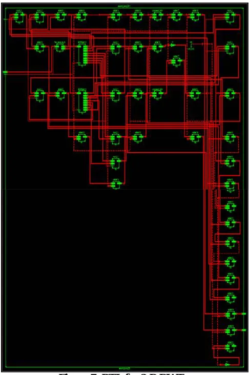
This figure 7 shows the RTL view of second level DWT. It has all the components of 2-D DWT. It contains all the shift registers, D-flip flops, BK adder. This RTL schematic depends on the view technology.
This figure 8 shows the waveform of the second level DWT. Here the input is given as ‘0011’ and the output finally comes for both the filters. ‘yh’ is ‘1111101000000000000’ for high pass filter output and ‘yl’ is ‘0000011000000000000’ for low pass filter output.
Figure 8: VHDL Test-bench in 2-D DWT
Table II:
2-D DWT using MDA Technique and Brent Kung Adder Technique
In this table 3, when it comes to 1-D DWT in case of ‘number of slices’ the proposed design is 56.6% better than the previous design, in case of ‘number of flip flops’ the proposed design is 33.3% better than the previous design, in case of ‘number of LUTs’ the proposed design is 29.2% better than the previous design, in case of ‘maximum delay’ the proposed design is 25.19% better than the proposed design. Similarly when it comes to 2-D DWT, the proposed design is much better than the previous design
Table III:
Comparison result of Existing Algorithm and Proposed Algorithm
Parameter 1-D DWT 2-D DWT
Previous Design
Proposed Design
Previous Design
Proposed Design Number of
Slice
346 150 752 514
Number of Slice Flip
Flop
48 32 454 224
Number of LUTS
359 254 1393 899
Maximum Combinational
Path Delay
23.146 ns
17.316 ns
28.998 ns
VI.CONCLUSION
The application of DWT has been seen in image processing, signal coding, audio and video processing, pattern recognition etc. DWT contains various techniques but here multiplier-less based technique is used as in previous design the same technique was used. For this MDA technique is used which provides approach for multiplier less implementation. It contains adder, shift registers and free of multiplier.
In previous design, Kogge stone adder was used for designing DWT but it was having the drawback that it was not working for every bit. So to remove this drawback, we have used BK adder which is an advanced binary adder. Its advantage is that it reduces the cost and the complexities of wire and is much quicker than Ripple Carry adder. So it provides better performance and less area to implement in comparison to KS adder. The main advantage of BK adder is that it works on every bit and consumes less space which was the main problem of previous design.
Finally we have designed the 1-D and 2-D DWT using BK adder and MDA technique which provide better efficiency and shows better results than the previous design.
REFERENCES
[1] Samit Kumar Dubey, Arvind Kumar Kourav and Shilpi Sharma, “High Speed 2-D Discrete Wavelet Transform using Distributed Arithmetic and Kogge Stone Adder Technique”, International Conference on Communication and Signal Processing, April 6-8, 2017, India
[2] Maurizio Martina, Guido Masera, Massimo Ruo Roch, and Gianluca Piccinini, “Result-Biased Distributed-Arithmetic-Based Filter Architectures for Approximately Computing the DWT”, IEEE Transactions on Circuits and Systems—I: Regular Papers, Vol .62, No.8, and August 2015.
[3] S.G. Mallat, “A Theory for Multiresolution Signal Decomposition: The Wavelet Representation”, IEEE Trans. on Pattern Analysis on Machine Intelligence, 110. July1989, pp. 674-693.
[4] M. Alam, C. A. Rahman, and G. Jullian, ”Efficient distributed arithmetic based DWT architectures for multimedia applications,” in Proc. IEEE Workshop on SoC for real-time applications, pp. 333 336, 2003.
[5] X. Cao, Q. Xie, C. Peng, Q. Wang and D. Yu, ”An efficient VLSI implementation of distributed architecture for DWT,” in Proc. IEEE Workshop on Multimedia and Signal Process., pp. 364-367, 2006.
[6] Archana Chidanandan and Magdy Bayoumi, “Area-Efficient MDA Architecture for the 1-D DCT/IDCT,” ICASSP 2006.
[7] M. Martina, and G. Masera, ”Low-complexity, efficient 9/7 wavelet filters VLSI implementation”, IEEE Trans. on Circuits and Syst. II, Express Brief vol. 53, no. 11, pp. 1289-1293, Nov. 2006.
[8] M. Martina, and G. Masera, ”Multiplierless, folded 9/7-5/3 wavelet VLSI architecture,” IEEE Trans. on Circuits and syst. II, Express Brief vol. 54, no. 9, pp. 770-774, Sep. 2007.