Finding Cutting Forces While Turning
Aperation on Lathe Machine at Different Depth
of Cut of Different Metals
B.Tulasiramarao
1, Dr.K.Srinivas
2, Dr. P Ram Reddy
3, A.Raveendra
4, Dr.B.V.R.Ravi Kumar
Assistant professor, Department t of Mechanical Engineering, Malla Reddy institute of Engineering Technology, Secunderabad, AP, India 1.
Professor, Department t of Mechanical Engineering ngg, RVR&JC college of Engineering, Guntur, AP, India 2 Professor, Department t of Mechanical Engineering, Dean Academics, Malla Reddy College of Engineering & Technology.
Secunderabad, AP, India3
Assoc. professor, Department t of Mechanical Engineering, Malla Reddy Engineering College, Secunderabad, AP, INDIA 4 Professor, Department t of Mechanical Engineering, VNRVJIET, Hyderabad, AP, India5
ABSTRACT:In this study, a lathe tool dynamometer that can measure cutting force, feed force and also thrust/Axial force
by using strain gauge accelerometer has been Studied and used. The dynamometer used in this project is a 500kg force 3-component system. The dynamometer is connected to a data acquisition system. As the tool comes in contact with the work piece the various forces developed are captured and transformed into numerical form system. In this project various forces for four different materials have been noted down and the materials used in this project are aluminum, brass, mid steel & nylon. The forces on these materials with variation in depth of cut are studied. Graphs are drawn on how these forces vary due to variation in depth of cut.
KEYWORDS: Depth of cut, Cutting speed and cutting force
I . INTRODUCTION
A. METAL CUTTING
The metal cutting is done by a relative motion between the work piece and the hard edge of a cutting tool. Metal cutting could be done either by a single point cutting tool or a multi point cutting tool. There are two basic types of metal cutting by a single point cutting tool. They are orthogonal and oblique metal cutting. If the cutting face of the tool is at 90o to the direction of the tool travel the cutting action is called as orthogonal cutting. If the cutting face of the tool is inclined at less than 90o to the path of the tool then the cutting action is called as oblique cutting. The differences between orthogonal and oblique cutting is given below
B. DYNAMOMETER
ISSN: 2319-8753
International Journal of Innovative Research in Science,
Engineering and Technology
(An ISO 3297: 2007 Certified Organization)
Vol. 3, Issue 10, October 2014
cut, feed rate, cutting speed, tool material and geometry, material of the work piece and other factors such as use of lubrication/cooling during machining.
C. NEED FOR MEASURING FORCES
The measurement of cutting forces in metal cutting is essential to estimate the power requirements, to design the cutting tool and to analyze machining process for different work and tool material combination.
Although cutting forces can be measured by different methods, the measurement of cutting forces by a suitable dynamometer is widely used in industrial practice. Mechanical and strain gauge dynamometer are most widely used for measuring forces in metal cutting. The principle of all dynamometers in based on the measurement of deflections or strain produced from the dynamometer structure from the action of cutting force.
II. OPERATING PROCEDURE
The work piece is held in the chuck and facing operation is performed to make the end face of the work piece flat. The work piece is centre drilled to provide tapered hole which can then accommodate and be supported by a running centre in the tail stock. Undercutting operation is done to provide a groove on the work piece in order to have a reference point Place the sensing unit of the dynamometer on lathe tool post and clamp rigidly. With the help of cable provided, carefully connect cable on sensing unit to socket on back plate of Force Indicator Unit .Connect Force Indicator to 230 V, single phase supply and switch ‗ON‘ supply. Wait for 5 to 10 minutes and then balance the channels to get zero readings on display with tare pots on the panel. Mount solid work – piece in the chuck .Adjust the speed & feed of the Lathe Machine and start the Machine. Feed the tool manually to start cutting and then feed it automatically .Wait to stabilize the output of the bridges and measure the maximum output for thrust, feed & radial forces. The Vertical, Horizontal & radial forces on the dynamometer should not exceed the limit 300 kg. Note down the reading and change depth of cut & repeat the same procedure. The following figure shows the operating procedure.
Fig.1. Aluminium rod during machining A. ALUMINIUM
Fig2: Aluminium before machining
It is nonmagnetic and does not easily ignite. A fresh film of aluminium serves as a good reflector of visible light and an excellent reflector of medium and far infrared radiation. The yield strength of pure aluminium is 7–11 MPa.
Fig 3 : Aluminium rod after several operation B. BRASS
Brass is an alloy made of copper and zinc; the proportions of zinc and copper can be varied to create a range of brasses with varying properties. It is a substitutional alloy: atoms of the two constituents may replace each other within the same crystal structure. It is used for decoration for its bright gold-like appearance. . The following figure shows the Brass before machining and after machining
Fig 4: Brass rod before machining
ISSN: 2319-8753
International Journal of Innovative Research in Science,
Engineering and Technology
(An ISO 3297: 2007 Certified Organization)
Vol. 3, Issue 10, October 2014
Figure 5: Brass rod after machining operation C. MILD STEEL
Mild steel, also called as plain-carbon steel, is the most common form of steel because its price is relatively low while
it provides material properties that are acceptable for many applications, more so than iron. The following figure shows the Mild steel before machining, machining and after machining
Fig 6: Mild steel rod before machining
Low-carbon steel contains approximately 0.05–0.3% carbon making it malleable and ductile. Mild steel has a relatively low tensile strength, but it is cheap and malleable; surface hardness can be increased through carburizing. It is often used when large quantities of steel are needed, for example as structural steel.
Figure 7: Mild steel rod after machining D. NYLON
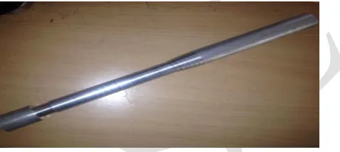
Nylon is a thermoplastic silky material, Solid nylon is used in mechanical parts such as machine screws, gears and
Fig8: Nylon rod before machining
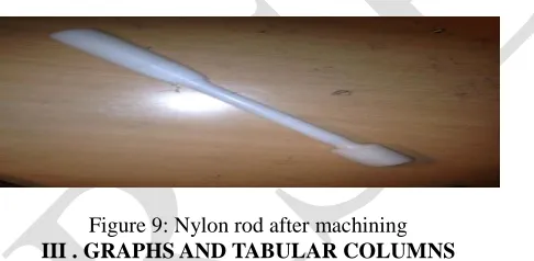
Variation of luster: nylon has the ability to be very lustrous, semi-lustrous or dull.
Durability: its high tenacity fibers are used for seatbelts, tire cords, ballistic cloth and other uses. High elongation Excellent abrasion resistance Highly resilient (nylon fabrics are heat-set)
Figure 9: Nylon rod after machining
III . GRAPHS AND TABULAR COLUMNS
The various forces such as cutting force, feed force and the axial force have been found out with the variation in depth of cut for Aluminium. Graphs are drawn on how these forces vary with the variation in the depth of cut for aluminium. It has been observed.
Speed: 630rpm Material: Aluminium
Table 1: Tabular column of variation of forces with variation in depth of cut Depth of cut Cutting force(fc) Feed force(ff) Thrust force(ft)
0.25 2 0 2
0.5 5 1 3
0.75 8 4 3
ISSN: 2319-8753
International Journal of Innovative Research in Science,
Engineering and Technology
(An ISO 3297: 2007 Certified Organization)
Vol. 3, Issue 10, October 2014
1.5 12 9 6
1.75 14 10 7
The various forces such as cutting force, feed force and the axial force have been found out with the variation in depth of cut for Brass. Graphs are drawn on how these forces vary with the variation in the depth of cut for Brass. It has been observed.
Speed: 630rpm Material: Brass
Table 2: Tabular column of variation of forces with variation in depth of cut
Depth of cut Cutting force(Fc) Feed force(Ff) Thrust force(Ft)
0.25 1 0 1
0.5 3 0 1
0.75 4 1 1
1 5 2 2
1.25 6 2 2
1.5 8 3 2
1.75 9 3 1
The various forces such as cutting force, feed force and the axial force have been found out with the variation in depth of cut for Mild Steel. Graphs are drawn on how these forces vary with the variation in the depth of cut for Mild Steel. It has been observed.
Speed: 630rpm Material: Mild steel
Table 3: Tabular column of variation of forces with variation in depth of cut
Depth of cut Cutting force(Fc) Feed force(Ff) Thrust force(Ft)
0.25 2 1 3
0.5 6 2 3
0.75 10 4 3
1 13 7 4
1.25 15 9 7
1.5 19 11 8
The various forces such as cutting force, feed force and the axial force have been found out with the variation in depth of cut for Nylon. Graphs are drawn on how these forces vary with the variation in the depth of cut for Nylon. It has been observed.
Speed: 630 rpm Material: Nylon
Table 4: Tabular column of variation of forces with variation in depth of cut
Depth of cut Cutting force(Fc) Feed force(Ff) Axial force(Ft)
1 0 0 0
1.50 0 0 0
2 1 0 0
2.50 1 0 0
3 1 1 1
3.50 2 1 1
IV. RESULT & CONCLUSION
In this project the various forces such as cutting force, feed force and the axial force have been found out with the variation in depth of cut for different materials like aluminium, brass, mild steel & nylon. Graphs are drawn on how these forces vary with the variation in the depth of cut. For aluminium and mild steel, It has been observed that with the increase in depth of cut, there is a linear increase in all the three forces. Whereas in case of brass and nylon there is uniform step increase in the forces with variation in depth of cut. And in this project we have studied, how a dynamometer works .And also learnt about various elements involved in metal cutting process.
For the further enhancement of this project a thermocouple if connected can be used to find the temperature developed during the machining process.
REFERENCES
1) G.Boothroyd,‘Fundamentals of machining and machine tools‘ 1sted,Scrapta Book Company‘.
2) W. E. Biles, James J. Swain, ―Optimization and industrial experimentation‖, 1980, John Wiley & sons, New York.
3) Muammer Nalbant, Hasan Gokkaya, and Ihsan Toktas¸2007. Comparison of Regression and Artificial Neural Network Models for Surface
Roughness Prediction with the Cutting Parameters in CNC Turning. Modelling and Simulation in Engineering. pp. 1- 14,
doi:10.1155/2007/92717
4) L. Andren, L. Hakansson, A. Brandt, I. Claesson, ―Identification of motion of cutting tool vibration in a continuous boring operation—
correlation to structural properties‖,Mechanical Systems and Signal Processing 18 (2004) 903–927, 29 September 2003.
5) http://www.constellium.com/aluminium-company/aluminium-properties and uses.
6) V. W Clack , R. C Brewer, R. C., ―New Technique for Shear zone Thickness . Determination in Orthogonal Metal Cutting‖ Proc. Inst. Of
Mech. Engrs., London, Vol. 181, pt. 1, 1966-67, p. 667.6).
7) http://www.azom.com/article.aspx?ArticleID=4387.
8) Armarego E., 2000, ―The Unified-Generalized Mechanics of Cutting Approach—A Step Towards a House of Predictive Performance Models