ISSN: 2319-8753
I
nternational
J
ournal of
I
nnovative
R
esearch in
S
cience,
E
ngineering and
T
echnology
(An ISO 3297: 2007 Certified Organization)
Vol. 2, Issue 9, September 2013
Copyright to IJIRSET www.ijirset.com 4383
CFD Analysis of Supersonic Exhaust in a
Scramjet Engine
1
Ramesha D.K.,
2Rudra Murthy
3Hemanth Kumar.P.
1
Associate Professor,
Department of Mechanical Engineering, University Visvesvaraya College of Engineering, Bangalore University, Bangalore-560001, India3
M.E.Scholar,
Department of Mechanical Engineering, University Visvesvaraya College of Engineering, Bangalore University, Bangalore-560001, India2
Assistant professor,
Department of Mechanical Engineering, KVG College of Engineering, Sullia,D.K-574327, IndiaAbstract: When pressures and temperatures become so high in supersonic flight that it is no longer efficient to slow
the oncoming flow to subsonic speeds for combustion, a scramjet (supersonic combustion ramjet) is used in place of a ramjet. This paper is aimed at modeling the supersonic flow inside Scramjet engine using the Computational Fluid Dynamics ANSYS Fluent. The purpose of this test is to validate FLUENT's ability to predict reflecting shock waves and their effect on wall pressure distribution and heat transfer. Supersonic flow from a nozzle that represents the exhaust nozzle of a supersonic combustion ramjet (SCRAMJET) is modeled. Jet from the nozzle is issued into a domain which is bounded on one side by an afterbody wall which is parallel to the centerline of the nozzle. Shocks propagating from the nozzle exit reflect from the afterbody. Measured values of the distribution of wall pressure and heat transfer rate along the afterbody are used to validate the CFD simulation.
In this study, k-ε model has been used to examine supersonic flow in a model scramjet exhaust. The configuration used is similar to the DLR (German Aerospace Center) scramjet model and it is consists of a one-sided divergent channel with wedge-shaped and without wedge shaped. For the purpose of validation, the k-ε results are compared with experimental data for temperature at the bottom wall. In addition, qualitative comparisons are also made between predicted and measured shadowgraph images. The k-ε computations are capable of predicting flow simulations well and good.
Keywords: Mach number, SCRAMJET, ANSYS, FLUENT, afterbody
I. INTRODUCTION
Scramjets are engines designed to operate at high speeds usually only associated with rockets and are typically powered by hydrogen fuel. Scramjet is an acronym for Supersonic combustion ramjet. A ramjet has no moving parts. Air entering the intake is compressed using the forward speed of the aircraft. The intake air is then slowed from a high subsonic or supersonic speed to a low subsonic speed by aerodynamic diffusion created by the inlet and diffuser. Fuel is then injected into the combustion chamber where burning takes place. The expansion of hot gases then accelerates the subsonic exhaust air to a supersonic speed. This results in a forward velocity. Scramjets on the other hand do not slow the free stream air down through the combustion chamber rather keeping it at some supersonic speed. This may appear mechanically simple however it is immensely more aerodynamically complex than a jet engine.
ISSN: 2319-8753
I
nternational
J
ournal of
I
nnovative
R
esearch in
S
cience,
E
ngineering and
T
echnology
(An ISO 3297: 2007 Certified Organization)
Vol. 2, Issue 9, September 2013
Copyright to IJIRSET www.ijirset.com 4384
third and final flight of the X-43A flown by NASA. This is three times the speed of the SR-71, officially the fastest jet-powered aircraft which achieved Mach 3.2.
II. GEOMETRIC MODEL
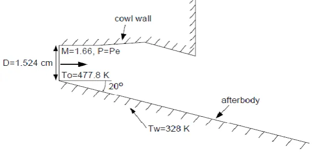
Supersonic flow from a nozzle that represents the exhaust nozzle of a supersonic combustion ramjet (SCRAMJET) is modeled. Jet from the nozzle is issued into a domain which is bounded on one side by an after body wall which is parallel to the centerline of the nozzle. Shocks propagating from the nozzle exit reflect from the after body. Measured values of the distribution of wall pressure and heat transfer rate along the after body are used to validate the CFD simulation.The flow is considered to be two-dimensional, because the span of the experimental outlet is considerably larger than the height. Both geometries are shown in Fig. 1 and Fig. 2. The flow enters the exhaust section at a Mach number of 1.66. In each case, the cowl wall opposite the after body angles initially upward. This is followed by a wedge, inducing a shock that reflects off of the after body.
Fig. 1: Sketch Showing Nozzle Separators and cowl
ISSN: 2319-8753
I
nternational
J
ournal of
I
nnovative
R
esearch in
S
cience,
E
ngineering and
T
echnology
(An ISO 3297: 2007 Certified Organization)
Vol. 2, Issue 9, September 2013
Copyright to IJIRSET www.ijirset.com 4385
III. INPUT PARAMETERS
A. Material Properties
Table 1 Material Properties
Property Values
Density(kg/m3) Ideal Gas
Molecular Weight 113.2
Viscosity(kg/m-s) 1.7894 X 10⁻⁵
Thermal
Conductivity(W/m-K) 0.0242
Specific Heat Temperature Dependent
B. Geometric Property
Table 2 Geometric Properties
Property Dimension
Nozzle outlet
diameter (cm) 1.524
Length of cowl
(cm) 3.5 D
C. Boundary Condition
Table 3 Boundary Conditions
Boundary Conditions values
Inlet Total Pressure (gauge) 551600 Pa
Inlet Static Pressure (gauge) 127100 Pa
Inlet Total Temperature 477.8 K
Inlet Turbulent Intensity 2 %
Wall temperature 328 K
ISSN: 2319-8753
I
nternational
J
ournal of
I
nnovative
R
esearch in
S
cience,
E
ngineering and
T
echnology
(An ISO 3297: 2007 Certified Organization)
Vol. 2, Issue 9, September 2013
Copyright to IJIRSET www.ijirset.com 4386
A pressure inlet is used such that the inlet Mach number is 1.66. The wall temperature (not given in [1]) is set to 328 K. A constant static pressure of 2780 Pa is used for the pressure outlet condition at the top and right of the geometries shown in Fig 2.The authors of the experimental paper [1] used a substitute gas without combustion. The substitute gas was chosen to give properties as close as possible to combustion gases used in practice. The gas used was a 60% Argon and 40% Freon-12 mixture at a total temperature of 477.8 K. Tables were provided in [1] giving the specific heat at constant pressure for temperatures between 111 K and 533 K. For the flow calculation, Cp was assumed to have a piecewise-linear dependence on temperature. Three points were used to define the curve at 205.6 K, 438.9 K, and 533.3 K
.
IV. CFD MESHING
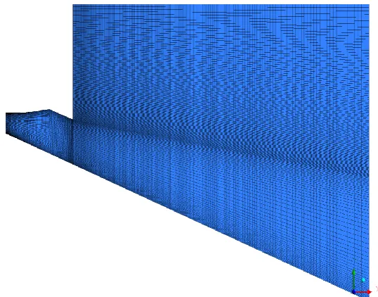
Two-dimensional grids were made for the test of the 20-degree geometry. The CFD mesh was a 39230-cell mesh made entirely out of quadrilateral cells TheQuadrilateral grids are shown in fig. below.
Fig. 3: Quadrilateral Grid for 20-Degree Afterbody
V. RESULTS AND DISCUSSON
ISSN: 2319-8753
I
nternational
J
ournal of
I
nnovative
R
esearch in
S
cience,
E
ngineering and
T
echnology
(An ISO 3297: 2007 Certified Organization)
Vol. 2, Issue 9, September 2013
Copyright to IJIRSET www.ijirset.com 4387
Fig 4: Pressure contours 20-Degree Afterbody Fig. 5: Temperature contours 20-Degree Afterbody
with wedge with wedge
Fig 6 gives Pressure variation along the centerline 20-Degree Afterbody with wedge, as a function of horizontal distance. Pressure is maximum at the nozzle end as the exhaust gas moves away from the nozzle end pressure gradually decreases and take sudden peak near the wedge due to shock waves that is pressure concentration more. Across the wedge pressure again reduces because of 20 degree afterbody inclination with respect to nozzle axis.
ISSN: 2319-8753
I
nternational
J
ournal of
I
nnovative
R
esearch in
S
cience,
E
ngineering and
T
echnology
(An ISO 3297: 2007 Certified Organization)
Vol. 2, Issue 9, September 2013
Copyright to IJIRSET www.ijirset.com 4388
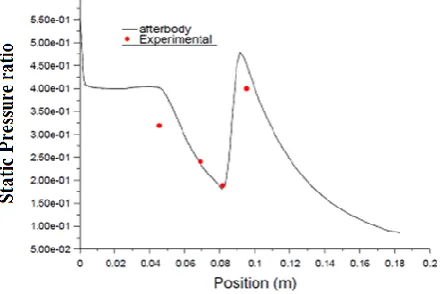
A. Comparison of predicted static pressure distribution on the 20- degree afterbody with wedge and experimental data
Fig. 7: Comparison of Predicted Static Pressure Distribution on the 20-Degree Afterbody with Experimental
Data
Fig. 7 describes the Normalized Pressure as a Function of Horizontal Distance for the 20-degree Afterbody with wedge and for the Hopkins et al. [1] Results.
B. Comparison of predicted total heat flux along the 20-degree afterbody with wedge and experimental data
Fig. 8 describes the Heat Transfer Rate as a Function of Horizontal Distance for 20-degree Afterbody and for the Hopkins et al. [1] Results.
ISSN: 2319-8753
I
nternational
J
ournal of
I
nnovative
R
esearch in
S
cience,
E
ngineering and
T
echnology
(An ISO 3297: 2007 Certified Organization)
Vol. 2, Issue 9, September 2013
Copyright to IJIRSET www.ijirset.com 4389
VI. CONCLUSION
It is interesting to note that obtaining experimental pressure measurements was a quicker process than CFD modeling in terms of both overall time taken and the time to investigate each configuration. However, CFD generates a much larger number of flow parameters than can be experimentally determined and is significantly less expensive, in terms of both personnel and equipment, than performing experiments in the shock tunnel. Also, once a model has been developed and verified subsequent modeling is significantly quicker and easier than experiments. Supersonic flow from a nozzle that represents the exhaust nozzle of a supersonic combustion ramjet (SCRAMJET) is modeled suing ANSYS Fluent. Jet from the nozzle is issued into a domain which is bounded on one side by an afterbody wall which is parallel to the centerline of the nozzle. Shocks propagating from the nozzle exit reflect from the afterbody. Measured values of the distribution of wall pressure and heat transfer rate along the afterbody are used to validate the CFD simulation. Pressure distributions obtained on a cowl and afterbody model with the flow of simulated combustion products and the flow from a substitute gas mixture of 50 percent Argon and 50 percent Freon 13Bl were in good agreement in the two -dimensional region of the flow.
REFERENCES
[1] Hopkins, H. B., Konopka, W., and Leng, J. “Validation of scramjet exhaust simulation technique at Mach 6”. NASA Contractor Report
3003, 1979.
[2] A. Lyubar and T. Sattelmayer “Numerical investigation of fuel mixing, ignition and flame stabilization by a strut injector in a scramjet
combustor.”
[3] Gerlinger, P., Möbus, H., Brüggemann, D. “An Implicit Multigrid Method for Turbulent Combustion”, Journal of Computational Physics,
2001, 166.
[4] Ro A. Oman K. M, Foreman, Jo Leng, and H. B. Hopkins “Simulation of hypersonic scramjet exhaust” Grumman aerospace
corporation for Langley Research Center NASA CR-2494, March 1975.
[5] Kristen Nicole Roberts. “Analysis and design of a hypersonic scramjet engine with a starting mach number of 4.0.” University of Texas
at Arlington in august 2008.
[6] Tohru Mitani, Toshinori Kouch “Flame structures and combustion efficiency computed for a mach 6 scramjet engine” Original
Research Article Combustion and Flame, Volume 142, Issue 3, August 2005.
[7] K.M.Pandey and T.Sivasakthivel“CFD Analysis of a Hydrogen Fueled Mixture in Scramjet Combustor with a Strut Injector by Using
Fluent Software”, IACSIT International Journal of Engineering and Technology, Vol.3, No.2, April 2011.