Development of an optically
synchronized seed source for a
high-power few-cycle OPCPA system
Izhar Ahmad
Development of an optically
synchronized seed source for a
high-power few-cycle OPCPA system
Izhar Ahmad
Dissertation
an der Fakult¨at f¨ur Physik
der Ludwig–Maximilians–Universit¨at
M¨unchen
vorgelegt von
Izhar Ahmad
aus Toba Tek Singh, Pakistan
Erstgutachter: Prof. Dr. Stefan Karsch
Zweitgutachter: Prof. Dr. Abdallah M. Azzeer
Contents
Zusammenfassung ix
Abstract xi
1 Introduction 1
1.1 Brief history of early laser development . . . 1
1.2 Applications of short pulsed lasers . . . 2
1.3 Motivation of ultrashort high power pulses . . . 3
1.4 Different techniques for amplification of short pulse lasers . . . 3
1.5 The Petawatt Field Synthesizer—PFS . . . 6
1.5.1 Schematic layout of PFS . . . 7
1.6 Thesis outline . . . 8
2 Seed generation and stretcher-compressor setup for the CPA pump laser 11 2.1 CPA pump laser seed generation . . . 11
2.2 Stretcher compressor setup for CPA pump laser chain . . . 14
2.2.1 Dispersion calculations . . . 14
2.2.2 Ray trace for the stretcher . . . 18
2.2.3 Ray trace for the grating compressor . . . 20
2.2.4 Alignment sensitivity . . . 21
2.2.5 Implementation of the stretcher and compressor . . . 24
2.3 Conclusion . . . 28
3 Chirped pulse amplification of the oscillator output 31 3.1 Femtopower amplifier upgrade . . . 31
3.1.1 Dispersion calculation of the amplified stretched pulse . . . 33
Contents
3.1.3 Hybrid pulse compression (HPC) . . . 39
3.2 All-dispersive mirror compressor . . . 43
3.2.1 Stretcher-compressor setups of conventional CPA systems . . . 43
3.2.2 Implementation of the ADMC . . . 44
3.2.3 Outlook . . . 46
3.3 Conclusion . . . 49
4 Broadband seed generation for OPCPA chain 51 4.1 Optical parametric amplification . . . 51
4.2 Idler generation using NOPA . . . 54
4.2.1 Design considerations . . . 56
4.2.2 Experimental setup for idler generation using NOPA . . . 61
4.3 Broadband seed generation using cascaded spectral broadening . . . 64
4.3.1 Spectral broadening in gaseous media . . . 65
4.3.2 Experimental setup . . . 67
4.3.3 Generation of few-cycle light pulses . . . 69
4.3.4 HCF-filament . . . 72
4.3.5 Cascaded-HCF . . . 74
4.4 Comparison of different OPCPA seed generation methods . . . 77
4.5 OPCPA seed stretcher . . . 79
4.5.1 Characterization of the stretched seed-pulses . . . 81
4.5.2 Scheme of final compression . . . 82
4.6 Summary . . . 83
5 OPCPA using DKDP and timing synchronization measurements 87 5.1 Experimental setup . . . 88
5.2 Level of synchronization between the OPCPA pump and seed pulses . . . 89
5.2.1 Timing jitter measurements . . . 89
5.2.2 Results and discussion . . . 91
5.2.3 Active stabilization of timing jitter . . . 91
5.2.4 Timing jitter due to the change in beam pointing at the input of the com-pressor . . . 93
5.2.5 Timing jitter due to the change in beam pointing inside the compressor . 98 5.3 OPCPA experiments in DKDP . . . 100
5.4 Conclusion . . . 103
Contents
A List of optical components in the current CPA pump laser chain 109
B Dispersion calculations of a double-prism pair compressor 111
C Formulae for the peak power, peak intensity and peak fluence of a Gaussian pulse 117
Zusammenfassung
Optische parametrische Verstrkung (OPCPA), bei welcher kurze Pumppulse verwendet wer-den, bietet ein neues und vielversprechendes Konzept f¨ur die Verwirklichung einer Quelle, die H¨ochstleistungs-Lichtpulse mit einer Pulsdauer von nur wenigen Lichtzyklen erzeugt [1, 2]. Dieser Ansatz reicht weit ¨uber die Grenzen herk¨ommlicher Lasertechnologie hinaus [3, 4], und erlaubt durch die Verwendung von d¨unnen nichtlinearen Verst¨arkerkristallen und einer nicht-kollinearen optischen parametrischen Verst¨arkergeometrie (NOPA) eine beispiellos breitbandige Verst¨arkung. Durch die wenige pikosekunden kurzen Pumppulse k¨onnen ¨ausserst hohe Pump-intensit¨aten verwendet werden, die eine hohe Verst¨arkung in diesen d¨unnen Kristallen sicher-stellen. Die hohen Pulsenergien werden in Kristallen mit einem großen Durchmesser erreicht. Das Petawatt Field Synthesizer (PFS) Projekt am Max-Planck-Institut f¨ur Quantenoptik (Garch-ing) soll mit dieser neuartigen Technologie Lichtpulse mit einer Dauer von wenigen Lichtzyklen und einer Spitzenleistung im Petawattbereich herstellen.
Abstract
The scheme of short-pulse pumped optical parametric chirped-pulse amplification (OPCPA) of-fers a promising route towards a completely new regime of ultra-high power few-cycle pulse gen-eration [1, 2], which reaches well beyond the limits of the conventional laser technology [3, 4]. In this approach, the gain bandwidth limitations of conventional laser amplification are circum-vented by using thin OPA crystals in a non-collinear pump-signal geometry (NOPA), while the high gain and pulse energies are ensured by the intense pumping and large crystals sizes. The Petawatt-Field-Synthesizer (PFS) project at the Max Planck Institute of Quantum Optics (Garch-ing, Germany), aims at delivering waveform-controlled few-cycle laser pulses with PW-scale peak power based on few-ps pumped OPCPA.
Chapter
1
Introduction
1.1
Brief history of early laser development
Light amplification by stimulated emission radiation—laser, is considered as a landmark in-vention of the Physics in the mid-20th century. Albert Einstein’s proposal [5], that photons could stimulate emission of identical photons from excited atoms, is considered as a conceptual building block of the laser. The first experimental recognition of his idea took place in ruby in 1960 [6]. In the following years, much effort was expended for exploring new laser transitions in various media: crystalline solids, gases, liquids etc. Utilizing this variety of media it was soon possible to observe laser transitions in a very wide spectrum, ranging from the vacuum ultraviolet (VUV) to the mid-infrared (mid-IR) [7]. Lasing action in the near infrared (NIR) was reported in He-Ne gas mixtures [8] followed by that in Nd+3doped solid-state materials in 1961 [9]. In the same year, population inversion in semiconductor materials was demonstrated, emitting in the NIR spectral range [10]. In 1961, the so-called giant optical pulsation was discovered in Ruby by the Kerr-effect Q-switching technique [7]. In 1962 the stimulated emission in He-Ne at a visible wavelength of 632.8 nm was demonstrated [7]. The laser transitions in the mid-IR at 10 µm in
the vibrational-rotational states of the CO2 molecules were discovered in 1964 [11]. This was
followed by a high power CO2 laser delivering 200 W in continuous wave (CW) mode [12].
The first optically pumped dye laser action was reported in 1966 [13]. In the subsequent years a number of dye solutions were discovered emitting laser radiation tunable in the visible and in the NIR [7]. The discovery of the Excimer laser in 1971 showed the possibility of direct lasing, without frequency up conversion, at 173 nm in the VUV spectral region [14].
1.2. Applications of short pulsed lasers
well as peak intensity (i.e. pulse energy per unit time per unit area). The quest to reach high in-tensity for studying laser-matter interactions and to explore the secrets of nature such as atomic or molecular structures by reducing the observation timing window demands the lasing opera-tion in the ultrashort pulse mode. The laser sources emitting broadband spectra were requisite for obtaining such short pulses owing to the fact that the shortest achievable pulse duration from an optical spectrum is inversely proportional to its bandwidth [15]. The dye lasers were the first in the race of ultra-short pulse generation owing to their tunable and, rather, broad output spectrum [16]. In the early 1970’s, Q-switched mode locking of the dye laser output produced sub-picosecond long pulses (1 ps=10−12s) at kW-level peak power [17, 18]. This innovation led to interest in solid-state lasers with vibronic transitions, in which electronic transitions strongly interact with atomic vibrations, so the resulting vibronic transition show a broad gain bandwidth. In 1980 Walling et al. [19] demonstrated a cobalt-doped alexandrite laser widely tunable in the 700–800 nm spectral range operating in both CW and pulsed mode. In 1988 Moulton [20] pi-oneered today’s most important tunable solid-state laser, titanium-doped sapphire (Ti:Al2O3)
which have excellent thermal properties and an exceptionally broad gain-bandwidth of 660 nm to 1180 nm. A big boost to producing short pulses came from the development of Kerr-lens mode-locking in 1991 [21], in which focusing within the Ti:sapphire crystal results in bunching of a laser pulse circulating within the laser cavity. This new technique allowed a self-mode-locked Ti-sapphire laser to generate pulses as short as 60 femtosecond (1 fs=10−15 s). Later, utilization of intracavity dispersion management with state-of-the-art chirped mirror tech-nology helped to reduce the pulse duration to below 10 fs [22, 23]. Nowadays sub-5 fs lasers have become turn-key devices in research laboratories.
1.2
Applications of short pulsed lasers
Chapter 1. Introduction
atomic and electronic dynamics on ever shorter time-scales calls for light pulses with subfem-tosecond (atsubfem-tosecond, 1 as=10−18 s) duration [27]. A techniques of higher order harmonic generation (HHG), in which a highly nonperturbative interaction of an intense few-cycle laser with an atomic or molecular medium generates new frequencies [28, 29, 30, 31], is generally employed for attosecond pulse generation [27, 32]. Real-time observation of ultrafast-dynamic processes can be achieved by the attosecond pump-probe experiments. Recent advancement in this field has provided a real-time picture of the valence-electron motion using attosecond light pulses [33].
1.3
Motivation of ultrashort high power pulses
High-power, few-cycle light pulses are of great interest for studying laser-matter interactions in the relativistic regime, i.e. at an intensity level in excess of 1018 W/cm2 which leads to relativistic electron motion in the laser field. A number of applications such as the generation of monoenergetic electron beams or the generation of intense single attosecond pulses from solid-density plasmas has been emerged from this field [34, 35, 36, 37, 38] and call for light sources delivering ever shorter and more powerful pulses. Experiments so far have established the fact that these interactions are highly sensitive to premature heating of the target caused by a non-ideal temporal contrast (i.e. the ratio of light emitted before the main peak and the main peak itself). As an additional benefit, shorter pulses require less total energy for a given peak power. As suggested by theory [39], the relativistic interaction of such a laser pulse with a solid surface is a promising candidate for high efficiency generation of higher-order harmonics and the production of high-intensity, high-energy attosecond-pulses. While experimental evidence already exists in support of this mechanism [38], in order to exploit it to its full extent a few-cycle, petawatt-class driver laser is necessary. Also the acceleration of electron bunches would benefit from this new laser source. Here, improved stability is expected [37] making such bunches more suitable for further applications [40]. Another important application is proton acceleration with high intensity laser pulses (> 1021 W/cm2) [41, 42], which can lead to effective use of proton beams for medical applications [43].
1.4
Different techniques for amplification of short pulse lasers
1.4. Different techniques for amplification of short pulse lasers
Figure 1.1:Principle of chirped pulse amplification
amplification (CPA) technique was first introduced by Strickland and Mourou [3] to overcome the problem of nonlinear effects and optical damage with increasing energies of short pulses. The amplifiers, in this scheme, are seeded with low-energy pulses temporally broadened in a dispersive pulse stretcher to permit for amplification without damaging the gain medium. The chirp of the amplified pulses is subsequently removed in a pulse compressor introducing a group-delay dispersion (GDD) of opposite sign. The pulse duration is thereby restored close to that of the input pulse (Fig. 1.1). The pulse stretching and compression can be obtained by a number of different setups such as, grating pairs [45, 46], prism pairs [47], grism pairs (a combination of a grating and prism) [48], high-dispersive mirrors [49], and material [49, 50, 51] etc. A few of these stretcher and compressor setups will be discussed in chapters 2 and 3. Detailed description about the CPA can be found in Ref. [44].
Based on CPA, as high as PW level peak power amplification was first obtained in 1996 at the Lawrence Livermoore National Laboratories (LLNL, US), with 660 J of pulse energy at a width of 440 fs using neodymium glass (Nd:glass) [52, 53]. Similar systems were later developed at the Rutherford Appleton Laboratories (RAL, UK) and Osaka University (Japan) to deliver amplified compressed pulses of 500 fs with 670 J [54] and 470 fs with 420 J [55], respectively. In the meantime a 0.85 PW CPA system was reported to yield 33-fs 28-J [56] pulses at the Japan Atomic Energy Research Institute (Japan) by utilizing the broader gain-bandwidth of Ti:sapphire [20].
Despite such achievements, conventional CPA laser systems suffer from gain narrowing as well as limited gain-bandwidth of the available amplification media and therefore approach an ultimate limit for scaling to the short-pulse regime without subsequent broadening using self-phase modulation techniques [57, 58]. The broadening techniques also have limitations in their scalability to high energy levels. Moreover, some additional issues such as self-oscillation of laser amplifiers in transverse directions (i.e. transverse lasing) and thermal lensing result in degradation of the amplification process and spatio-temporal quality of the compressed pulses.
Chapter 1. Introduction
i.e. population inversion of an amplification medium under excitation from a pump, optical para-metric amplification (OPA) [59] originates from a three-wave mixing process inside a nonlinear crystal. Here, a short-wavelength high-intensity beam, the pump, amplifies a longer-wavelength lower-intensity beam, the signal, in a nonlinear medium. This interaction leads to the sponta-neous generation of a third beam, the idler, so that the energy and momenta are conserved be-tween the three beams. Owing to the very broad gain-width that can be achieved in the nonlinear frequency mixing process, the amplified spectrum can support few-cycle pulse width [60]. When combined with the CPA approach, the nonlinear wave mixing process (termed as optical para-metric chirped pulse amplification (OPCPA) [4]) enables us to reach ultra high powers [51, 61].
There are many aspects which make the OPCPA better suited than lasers for realizing a high-power short-pulse light source. Firstly, the parametric amplification is an instantaneous and propagation-direction dependent process which make it intrinsically free from the transverse las-ing hence removlas-ing one substantial limitation of high power CPA laser systems. Secondly, the single-pass gain in OPA system is much higher than that of the conventional CPA lasers [4, 62] therefore only a few single-pass stages are required for the achieving the same gain, hence avoid-ing the complexities of multipass cavities. Thirdly, in the case of the OPCPA, the energy differ-ence between the pump and the signal waves is released in form of an idler wave, rather than that of heat as in CPA lasers, which, being less absorbed in the nonlinear crystal, causes significantly lower thermal load. This feature is a great benefit for high average power systems. Fourthly, the idler wave can also be useful in some case; e.g. generation of a short pulse [63] or seeding an amplifier [64, 65] in a spectral region difficult to reach with conventional techniques. Finally, OPCPA provides many degrees-of-freedom to obtain large amplification bandwidths such as the nonlinear crystal and the geometry of the nonlinear interaction etc. [4, 60]. This allows for higher flexibility in the conception and optimization of the amplifier design, as compared to the systems which are restricted to the laser amplifier medium. These features make parametric amplification more attractive, particularly for the amplifier dedicated for high-intensity applications. Nonethe-less, the absence of energy storage imposes strict requirement for temporal overlap of the pulses inside the crystal to ensure interaction between the pump and the signal pulses. Precise control over the pulse timing is hence required to achieve reasonable conversion efficiency. This issue clearly becomes especially severe at shorter pump pulse duration.
Based on OPCPA, the first PW-level peak power OPCPA system with 24 J in 43 fs was demonstrated in 2007 [61] using DKDP (Potassium Dideuterium Phosphate: KD*P). This was followed by 80-mJ 8.5-fs (≈10 TW) parametric amplification in BBO (Beta Barium Borate: β
-BaB2O4). A 1.1-PW hybrid laser system utilizing both the OPCPA and conventional CPA-based
1.5. The Petawatt Field Synthesizer—PFS
at the RAL, UK [67]; 10 PW (150 J, 15 fs) APPOLON at the Institute Lumiere Extreme [68], France; and 200 PW pan-European Laser facility, “The Extreme Light Infrastructure—ELI [68, 69]”.
In most of the PW-class light sources, reported to date [53, 54, 55, 56, 61, 66], the pump pulse duration range from 100 ps to few-ns, while the output compressed pulses could only reach down to a duration of a few-tens of femtoseconds. The PW-level amplification with few-cycle com-pressed pulses is yet to be demonstrated and constitutes the main goal of the development of the Petawatt Field Synthesizer (PFS) infrastructure at the Max-Planck Institute of Quantum Optics (MPQ), Germany. In the following section a brief overview of the PFS-design is presented.
1.5
The Petawatt Field Synthesizer—PFS
The PFS system is designed to deliver few-cycle (5 fs) laser pulses with an energy of>3 J and a repetition rate of 10 Hz. The focussed intensity is expected to reach or exceed 1022 W/cm2[1]. The design of the PFS is based purely on OPCPA technology but with some modifications of the conventional designs. Here, high power, few-ps pump pulses are used to amplify a broadband signal in thin OPA crystals to achieve multi-Joule energy in few-cycle pulse durations [2]. The thin OPA crystals ensure large bandwidth in a noncollinear pump-seed arrangement [60], while the high gain and pulse energies are achieved by intense pumping and large crystal size, re-spectively. This technique possesses immense potential for generating pulses of significantly enhanced contrast, compared with the conventional long-pulse pumped OPCPA, due to the short time window for the parametric fluorescence. Moreover, very simple, compact, and high throughput stretcher-compressor systems, such as bulk glass and chirped mirrors, can be used owing to the small stretching factor. The requirement of high level of temporal synchronization between the pump and seed pulses during parametric amplification in this scheme, to ensure sta-ble gain, calls for an optical synchronization technique where the seed pulses for both the pump and OPCPA chain are derived from a common source (master oscillator: MO). The detailed description of the PFS design is presented in Ref. [2].
Chapter 1. Introduction
To allow for broadband amplification with reasonable gain, DKDP is chosen to be the host for nonlinear wave-mixing in the OPCPA chain owing to its availability in large aperture as well as broad amplification bandwidth in the range of 700–1400 nm [75] in a noncollinear pump-signal arrangement. The anticipated total pump energy of 15-20 J at 515 nm will be used to amplify theµJ level broadband signal pulse (OPCPA-seed) in 7 or 8 OPCPA stages to achieve the design
goals [2]. The design requires the broadband OPCPA-seed pulse to be temporally stretched to 1-2 ps in order to match with the pulse duration of the pumping source to make the OPA process more efficient and to allow for damage-free amplification. This small stretching factor can be achieved by a negative dispersion device, e.g. a prism pair and/or chirped mirrors, which in turn allow for simple and efficient recompression using few-tens of milimetres bulk material alone or in combination with chirped mirrors. The beam diameter can be adjusted such as to avoid the intensity-dependent nonlinear effects.
1.5.1
Schematic layout of PFS
The planned layout of the PFS system is schematically shown in Fig. 1.2. The “CPA pump chain” is dedicated for the development of the PFS pump laser at 1030 nm, while the “OPCPA chain” will amplify the ultrabroadband signal using nonlinear frequency mixing in OPA crystals when pumped at 515 nm (frequency doubled output of PFS pump source). The CPA-pump and
Figure 1.2:Planned layout of the PFS system.
1.6. Thesis outline
spectral shifting to the pump laser wavelength of 1030 nm while the other is further amplified in a Ti:sapphire amplifier for broadband OPCPA seed generation. The spectrally shifted output of the PCF is pre-amplified in the Yb:doped fibers to boost the CPA-pump laser seed energy before injecting it into the pulse stretcher (discussed in Chapter 2). These stretched pulses are amplified in a chain of amplifiers (H1–H4) to deliver a total of∼50 J at 10 Hz in four beams with amplified
spectrum supporting a pulse width of 1-2 ps. The amplified pulses are subsequently compressed and frequency doubled to pump the OPCPA chain at 515 nm.
The broadband OPCPA seed (700–1400 nm) is generated at the common frontend using a cascaded hollow core broadening technique (discussed in Chapter 4). The seed pulses are temporally stretched in a negative dispersion prism pair in order to match the pulse duration of the pump laser. These pulses are subsequently amplified in the OPCPA chain of 7-8 OPCPA stages (for clarity only 5 such stages are depicted in Fig. 1.2). The amplified pulses are recompressed in a bulk-material compressor.
1.6
Thesis outline
In this dissertation, the development of the common frontend for the PFS system is presented which provides optical synchronization between the OPCPA beam-line and the pump source us-ing a state-of-the-art commercial Ti:sapphire oscillator-amplifier system. The design and devel-opment of a stretcher-compressor system for the CPA-based pump laser is detailed. A scheme for dispersion management of the broadband OPCPA seed pulses and first results of the short-pulse pumped OPCPA seeded by this frontend are presented. A short survey of the thesis structure is as follows:
• The seed generation for the CPA-chain of PFS system is discussed in Chapter 2. The design and development of the stretcher-compressor setup for the CPA-chain is presented. Different aspects which can affect the pulse quality of the stretched and recompressed pulse are highlighted. The results of compression of the amplified stretched pulses are also summarized.
Chapter 1. Introduction
• Different methods for broadband OPCPA seed generation in the spectral range of 700– 1400 nm are discussed in Chapter 4. A scheme of idler generations using noncollinear OPA is described. The results of theoretical calculations for idler generation are presented. A technique of angular chirp compensation is discussed. The preliminary results of the experimental setup for idler generation are discussed. The schemes of cascaded spectral broadening using HCF-filamentation and cascaded-HCF for broadband supercontinumm generation are detailed. The NIR-parts of such spectra are then analysed for seeding the OPCPA chain of PFS. The dependence of gas-pressure and input pulse-energy on the in-frared part of the supercontinuum is discussed. A new kind of double-angle chirped mir-rors are introduced for few-cycle pulse generation. Moreover, the design of the OPCPA seed stretcher and compressor is presented.
• Measurement of the level of temporal synchronization between the OPCPA pump and signal is described in Chapter 5. Theoretical calculations of the temporal jitter introduced by the beam pointing fluctuations in the stretcher-compressor setup of the CPA-chain are presented. The proof-of-principle experiments for broadband parametric amplification in thin DKDP performed at the first stage of the PFS OPCPA chain are presented.
Chapter
2
Seed generation and stretcher-compressor
setup for the CPA pump laser
In this chapter a scheme for seed generation for the CPA pump-laser chain of the PFS system (cf. Fig. 1.2) is discussed. The design and development of a stretcher-compressor setup for the CPA chain is presented. Different aspects such as grating alignment sensitivity and angle of incidence which can affect the pulse quality of the stretched and recompressed pulses in the sretcher and compressor are also summarized.
2.1
CPA pump laser seed generation
2.1. CPA pump laser seed generation
the amplified pulses [76, 77]. One solution for avoiding such undesired effects is to use high energy seed pulses [77].
In order to obtain energetic seed pulses for the CPA-based pump laser chain of the PFS from a part of the output power of the master oscillator (MO), we employed a spectral shifting scheme based on soliton self-frequency shift (SSFS) [78] in a photonic crystal fiber (PCF) [51, 78, 79]. This scheme is considered more efficient as compared to the spectral broadening techniques based on self-phase modulation [80] at such small pulse energies. The SSFS in a PCF originates from the intrapulse stimulated Raman scattering, which transfers the high-frequency, or short-wavelength, part of the pulse spectrum to the low frequency, or long wavelength. Optical soliton pulses generally experience a continuous downshift of their carrier frequencies when they are propagating in a PCF with anomalous group velocity dispersion (GVD<0) [81, 82]. The PCF substantially enhances this nonlinear optical process [83] due to a strong field confinement in a small-size fiber core and the possibility to tailor dispersion of guided modes by varying the fiber structure [84]. Moreover by varying the input energy and the length of the PCF, central wavelength of the red-shifted spectrum can be fine tuned. As discussed by Serebryannikov et al. [85], the radiation energy carried by the soliton is localized in the time domain within a short spike which, during its propagation through the fiber, dominates the main temporal envelope of radiation intensity. Owing to the anomalous group-velocity dispersion of the PCF, the red-shifted soliton becomes delayed and eventually isolated, both spectrally and temporally, with respect to the rest of the pump field. This isolation of the frequency-shifted soliton suppresses the interference between the solitonic part and the rest of the spectrum of radiation field. In this way the output red-shifted spectrum is significantly less modulated, making it better suited for seeding the amplifiers.
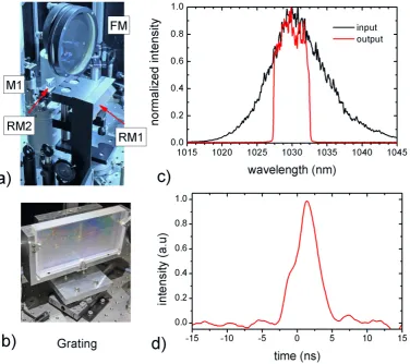
The schematic sketch of the experimental setup is shown in Fig. 2.1(a). The output of the MO was divided into two parts using a broadband beam splitter (BS). One part is utilized for OPCPA seed generation, the details of which are presented in next chapters. The other part of the MO output ( 100 mW, 1.4 nJ) was focused by a 0.25 numerical-aperture microscope objective (see Fig. 2.1(b)) into a 1.6-µm core diameter 25-cm long PCF ( NL-PM-750 PCF; Crystal Fibre Ltd.)
mounted on a very stable 3-D translation stage (Nano Max-313, Thorlabs) for spectral shifting at the CPA-pump laser wavelength of 1030 nm. Very fine displacement of the PCF entrance along the beam propagation axis, which in turn changes the coupling into the fiber, helps in fine-tuning the central wavelength of the soliton spectrum. Under optimum conditions an overall thoughput of∼30% was observed after the PCF with a broadband supercontinuum shown in grey shaded area in Fig. 2.1(c). An interference filter selected a∆λ =10 nm band centred at 1030 nm from
Chapter 2. Seed generation and stretcher-compressor setup for the CPA pump laser
Figure 2.1:(a) Schematic layout of the experimental setup. BS: beam splitter; Mic.Ob: micro-scopic objective; PCF: photonic crystal fiber; TS: 3D-translation stage; L: lens; IF: interference filter; FA: fiber amplifiers; Regen.: regenerative amplifier; H0, H1 and H2 are according to the schematic layout of the PFS shown in Fig. 1.2. (b) Picture of the apparatus used for spectral shifting at 1030 nm. (c) Input and output spectra of the PCF. The filled area highlighted in yel-low indicates the 10-nm FWHM band spectrum after an interference filter. All the spectra are normalized to their peak values.
2.2. Stretcher compressor setup for CPA pump laser chain
compressor setup for the CPA pump laser are presented in the following section.
2.2
Stretcher compressor setup for CPA pump laser chain
2.2.1
Dispersion calculations
In order to stretch the ∼3.5-nm (FWHM of spectral intensity) seed pulse for the CPA-chain of the PFS system, a modified all-reflective grating stretcher [86] was designed. It is based on the principle of conventional Martinez-type grating stretcher [46] which comprises a pair of gratings, a 1:1-imaging telescope, and an end mirror as shown in Fig. 2.2. In this setup each beam leaving the first grating (grating1) with an angle β is sent on the second grating
(grating2) with an incidence angleβ0=−βby a 1:1 imaging telescope. Therefore all the spectral
components are diffracted at the same angle−α from the second grating. In this way the redder spectral components (compared to the central wavelength) of the pulse travel shorter or longer optical paths between the gratings, depending on the position of the grating2, than the bluer ones, introducing a wavelength-dependent delay. Moreover in this configuration the image of the grating1 and grating2 through the telescope forms a Treacy-type grating compressor [45], for identical angle of incidence and spectral range, with separationL1= f1−z1along the central wavelengthλ0. The dispersion introduced by such a stretcher therefore matches with that of the
Treacy-type grating compressor [87, 88].
The frequency dependent spectral phase of a frequency component ω after a Martinez-type
stretcher can be written as [46, 89]
Φ(ω) =Xω
c ·`cos(β−β0), (2.1) where `= (z1−f1)M2+ (z2− f2); z1 and z2 are the distances of respective gratings from the principle planes of the telescope lenses as shown in Fig. 2.2;M= f2
f1 is the magnification factor of the imaging telescope, equal to one in our consideration; X denotes the number of passes of the incident pulse through the stretcher, e.g. equal to two in Fig. 2.2;β andβ0are the first-order
diffraction angles from a grating corresponding to an angle of incidence ofα for the wavelength
componentsλ (=2πc/ω)andλ0as given by
β =arcsin(Nλ−sinα), (2.2)
and
β0=arcsin(Nλ0−sinα), (2.3)
Chapter 2. Seed generation and stretcher-compressor setup for the CPA pump laser
Figure 2.2: Principle of a grating-based stretcher compressor setup with matched dispersion. The right hand side of the picture denotes a Martinez-type stretcher [46] where each beam leav-ing the gratleav-ing1 with an angleβ is sent on the grating2 with an incidence angleβ0=−β by a
1:1 imaging telescope. Therefore all the spectral components are diffracted at the same angle
−α from the second grating. The end mirror redirects the beam to fold the optical path. The
image of the two gratings forms a Treacy-type parallel grating compressor [45] (left hand side of the picture) with matched dispersion for a grating separation L1= f1−z1alongλ0[87]. Here
for clarity the imaging system is shown with lenses instead of mirrors as for our real design.
The spectral phase of a frequency component ω can be expanded around the central
fre-quencyω0=2πc/λ0using the Taylor series as follows
Φ(ω) =Φ(ω0) +
(ω−ω0)
1! · ∂Φ ∂ ω
ω=ω0
+(ω−ω0)
2
2! ·
∂2Φ
∂ ω2
ω=ω0
+(ω−ω0)
3
3! ·
∂3Φ
∂ ω3
ω=ω0
+· · ·
=Φ(ω0) +
(ω−ω0)
1! ·D1+
(ω−ω0)2
2! ·D2+
(ω−ω0)3
3! ·D3+· · ·
(2.4)
The coefficientsD1= ∂Φ ∂ ω
ω=ω0
, D2= ∂2Φ ∂ ω2
ω=ω0
, D3= ∂3Φ ∂ ω3
ω=ω0
are termed as group-delay (GD), group-delay dispersion (GDD), and third-order dispersion (TOD), respectively. The ex-pression (Eq. 2.4) can be expanded to higher order terms, however we assume that for the spec-tral bandwidth of our setup the influence of those terms on the pulse duration will be negligible. Differentiating Eq. 2.1 with respect toω up to three orders we have
∂Φ(ω) ∂ ω =
X` c·
cos(β−β0)−ωsin(β−β0)
dβ
dω
(2.5)
∂2Φ(ω) ∂ ω2 =−X
`
c·
"
2dβ dω +ω
d2β
dω2
sin(β−β0) +ω
dβ
dω 2
cos(β−β0)
#
2.2. Stretcher compressor setup for CPA pump laser chain
∂3Φ(ω)
∂ ω3 =−3X ` c dβ dω 2
1+ω d
2
β
dω2
dβ
dω
cos(β−β0)
−X` c 3
d2β
dω2+ω
d3β
dω3−ω
dβ
dω 3!
sin(β−β0)
(2.7)
Simplifying Eqs. 2.5– 2.7 for ddβ
ω =
−2πcN ω2cosβ and
d2β dω2 =
4πcN ω3cosβ
1+πcNsinβ
ωcos2β
(cf. Eq. 2.2) under condition ofω→ω0we obtain
D1=X·
`
c (2.8)
D2=−X·`
c·
λ0
2πc
λ0N
cosβ0
2
(2.9)
D3=3X·`
c·
λ0
2πc 2
λ0N
cosβ0
2
1+λ0Nsinβ0
cos2β 0
(2.10)
By assuming a Gaussian spectrum of the input pulse, following expression can be used for the estimation of required GDD for stretching a nearly transform limited (TL) pulse τ0 to the
desired FWHM pulse duration of∆τ[88]
GDD= ∆τ0
4 ln 2
q
∆τ2−∆τ02 (2.11)
where∆τ0=2 ln 2πc λ02
∆λ and∆λ is the FWHM of the Gaussian shaped spectrum. In order to stretch
the seed pulse from∆τ0=560 fs, as calculated from the Gaussian spectrum assuming a FWHM
of 3 nm, to the desired pulse duration of 3 ns, the estimated GDD amounts to+6.14×10⁸fs2. As can be visualized from Eq. 2.9, a Martinez-type stretcher can provide both normal and anomalous dispersions depending on the sign of` whether it is negative or positive, respectively. However, in order to employ a Treacy-type parallel grating pair compressor, which provides anomalous dispersion, the effective distance`for the stretcher should be negative to get opposite sign of the dispersion.
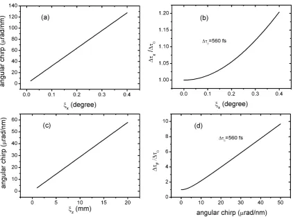
Figures 2.3(a) and (b) show the GDD introduced by the pulse stretcher as a function of the parameters ` and α at λ0 =1030 nm. The calculations have been performed for a
Martinez-stretcher configured in a double-pass (X=2) arrangement using a pair of N=1740-lines/mm diffraction gratings and an M=1 imaging telescope (Fig. 2.2). The GDD introduced by the stretcher varies linearly with respect to the effective length`(Eq. 2.9), however it also depends very sensitively on the angle of incidence (Figs. 2.3(a,b)). The dependence of calculated GDD for three different values ofα is shown in Fig. 2.3(a). The slope of the GDD changes from neary +1×10⁸fs2/m to+6.24×10⁷fs2/m for a change inα from 58.5◦to 63◦(see more details in
Chapter 2. Seed generation and stretcher-compressor setup for the CPA pump laser
Figure 2.3:Calculated GDD introduced by the Martinez-stretcher [46] set up for a double-pass (X=2) configuration using N=1740-lines/mm diffraction gratings and M=1 imaging telescope (Fig. 2.2). (a) Dependence of GDD on effective distance`for α =58.5◦,60◦, and 63◦. (b)
Calculated GDD as a function ofαfor a fixed value of`of 6 m (cf. Eqs. 2.3, 2.9).
from an angle of 58.5◦ and a stretching/compression ratio of ≈5000 results in an uncompen-sated GDD of ±1.28×10⁷fs2, and TOD of∓6.39×10¹⁰ fs3, which can change a pulse, given the parameters of our setup, upto two orders of magnitude compared to its TL width. Here the residual GDD is corrected by changing the grating separation, whereas the TOD and higher or-der terms will remain uncompensated. Moreover, different grating separation can provide the same stretching factor at differentα as elaborated in Fig. 2.4(a). In order to provide the design
GDD of +6.14×10⁸ fs2, the required distance` for the stretcher increases from nearly −3 m to −10 m when α changes from ∼55◦ to 63◦. These results favour small angle of incidence
for incoming beam in order to construct a compact stretcher and compressor setup. However the diffraction efficiency of the grating which, dominantly, defines the overall throughput of the setup changes in the opposite way. It exhibits maximum diffraction efficiency in a specific diffraction-order near the Littrow angle and less elsewhere. As can be seen from Fig. 2.3(b), the measured first-order diffraction efficiency for our available N=1740-lines/mm multilayer diffrac-tion (MLD) grating [90] for a p-polarized light reduces from∼94% to 82%with a decrease of 11◦in the angle of incidence from its Littrow angle of∼63◦at 1030 nm.
We employed an optimum angle of incident of 58.5◦, keeping in view both the diffraction effi-ciency of the gratings as well as the available space in the lab, for our stretcher and compressor setup which corresponds to an effective distance ` of −6.1 m in the stretcher for double pass (X=2) configuration (Fig. 2.2). The equivalent distanceL1alongλ0in the compressor, assuming
2.2. Stretcher compressor setup for CPA pump laser chain
Figure 2.4: (a) The dependence of distance`on the angle of incidence (α) (cf. Eqs. 2.1, 2.9),
for introducing a GDD of+6.14×10⁸fs2atλ0=1030 nm, in a Martinez stretcher set up for a
double-pass (X=2) configuration using N=1740-lines/mm diffraction gratings and M=1 imaging telescope (Fig. 2.2). (b) Measured first-order diffraction efficiency of the gratings, used in the experimental setup, at different values ofα.
gratings exhibit a diffraction efficiency of∼93.9% at this angle of incident for p-polarized light. In the following the design of our modified all-reflective grating stretcher is presented.
2.2.2
Ray trace for the stretcher
Figure 2.5 shows the beam propagation through our stretcher in the horizontal (xz) as well as vertical (yz) planes, with the z-axis being the propagation direction, as drafted using a ray-tracing program RAYTRACE [91]. It consists of a single grating, a spherical mirror, a flat mirror and two roof mirrors. The spherical and flat mirrors form a 1:1 imaging telescope, whereas the roof mirrors RM1 and RM2 provide two-times folding (X=4) geometry. A 200×100-mm2 grating
with N=1740 lines/mm was considered for ray tracing. A half-inch flat mirror (M1) steers the
incoming beam, having a 1/e2diameter of∼6 mm, to the grating (G) which diffracts it towards a 4-inch planoconcave mirror (FM) with a focal length of 2.65 m. The beam is then focused, by changing its height slightly above the grating, on a 4-inch flat mirror M2 positioned at the
focal plane of FM. A small tilt of∼0.4◦ of the FM in the vertical plane is enough to guide the beam toward the flat mirror and avoiding beam clipping on the grating. This mirror redirects the beam back to the FM to repeat this sequence in reverse order but at slightly different height. The beam exits the stretcher assembly after the first pass vertically displaced from the incoming beam. At this point, it is sent back for a second pass through the stretcher by a roof mirror RM1,
Chapter 2. Seed generation and stretcher-compressor setup for the CPA pump laser
Figure 2.5:The schematic layout of the CPA-seed stretcher with 4-times folding geometry, i.e. eight reflections off the grating as sketched by an optical ray-tracing software: RAYTRACE [91]. (a) Beam propagation in the xz-plane. (b) Beam propagation in the yz plane, where xz and yz denote the horizontal and vertical planes w.r.t the direction of propagation z of the beam. The sharp display of different optical components in (a) and (b) is due to the limitation of the RAYTRACE to resolve their orientations appropriately. The colour scheme of the RAYTRACE is such that for each optical element the incident and reflected ray is displayed with a different colour. (c) Top view of the stretcher: for illustration only the central wavelength (λ0) is shown.
2.2. Stretcher compressor setup for CPA pump laser chain
Table 2.1: Calculated coefficients of dispersion per unit effect grating separation (`) in a Martinez-type stretcher at different angles of incidence (α) for X=2, N=1740 lines/mm and
M=1 (Eqs. 2.9, 2.10):
α GDD/` TOD/` `for 6.14×10⁸fs2
[degree] [fs2/m] [fs3/m] [m] 58 1.08×10⁸ −2.93×10⁹ −5.69 58.5 1.00×10⁸ −2.51×10⁹ −6.14 59 9.32×10⁸ −2.19×10⁹ −6.59 60 8.24×10⁸ −1.71×10⁹ −7.45 61 7.41×10⁷ −1.38×10⁹ −8.28 62 6.76×10⁷ −1.15×10⁹ −9.08 63 6.24×10⁷ −9.82×10⁸ −9.84
displaced in the vertical direction from the input, but to the opposite side as the first pass, which is then redirected to the stretcher for two more passes by a second roof mirror RM2, horizontally
displaced by ∼10 mm. After 8 passes the beam exits the stretcher assembly displaced in the horizontal direction.
The required distance ` in the described setup with two times folding geometry (X=4), for providing the design GDD of +6.14×10⁸ fs2, is reduced to −3.05 m which correspond to z1=z2=1.8875 m (Fig. 2.2) or a separation of 762.5 mm between the grating and the focal plane of the FM (Fig. 2.5(a)). The calculated TOD of the stretched pulse for this separation is
−1.55×10¹⁰fs3(Eq. 2.10).
As discussed in Chapter 1, the design of the PFS requires the stretched seed pulses, centred at 1030 nm, to be amplified to 50 J energy in a chain of CPA stages. This total energy of 50 J will be achieved in four beams each containing≈12.5 J.∗In the following a design of the pulse compressor is presented to re-compress the amplified stretched pulses.
2.2.3
Ray trace for the grating compressor
As described in the previous the section, a Treacy-type parallel grating pair can provide a dis-persion matched with that of the Martinez-type stretcher. A separation ofL=6.1 m between the gratings along the wavelength componentλ0 is needed to provided a GDD of −6.14×10⁸ fs2
and a TOD of+1.55×10¹⁰ fs3, as calculated from Eqs. 2.9 and 2.10 by substituting|`|=−L. The optical path of four beams through the compressor is shown Fig. 2.6. We adapt a diameter
∗The design of these amplifiers is described in Ref. [2]. Additional details will be presented in the future
Chapter 2. Seed generation and stretcher-compressor setup for the CPA pump laser
Figure 2.6: The schematic layout of the CPA pulse compressor sketched by an optical ray-tracing software: RAYTRACE [91]. (a) Beam propagation in the xz-plane. (b) Beam propaga-tion in the yz plane, where xz and yz denote the horizontal and vertical planes w.r.t the direcpropaga-tion of propagation z of the beam. The inset in (a) depicts the designed assembly of four gratings at z=0 for four incident beams.
of ∼40 mm for the incident flat-top beams, equivalent to an energy fluence of <1 J/cm2 well below the reported damage threshold of 3-5 J/cm2for the MLD gratings [90, 92] for the param-eters similar to the PFS pump laser. However, for clarity a beam diameter of 10 mm is depicted in Fig. 2.6. The incoming beams propagate along the z-axis with their centres displaced from each other by ∼140 mm in the xy-plane in the shape of a square. They strike on four separate 200×100-mm2 gratings (denoted by G1, G01, G001, and G0001) at z=0 arranged in the xy-plane in
a fashion similar to the incoming beams with their edges having an offset of ∼40 mm from each other, see Fig. 2.6(a). After diffraction, all the beams impinge on a 800×400-mm2grating (G2) separated by 6.1 m along the wavelength componentλ0=1030 nm in the xz-plane, which
diffracts them towards a 500-mm diameter end mirror (M). This mirror redirects these beams to repeat the sequence in reverse direction for the second pass. At this position the beams are slightly tilted by<0.2◦in the upward direction (along the y-axis) in order to separate each beam from the incoming ones at the exit of the compressor (cf. Fig. 2.6(b)).
2.2.4
Alignment sensitivity
2.2. Stretcher compressor setup for CPA pump laser chain
Moreover even with the exact design, the material dispersion of the in-between laser amplifiers restricts the exact compensation of all orders of dispersion coefficients. The grating separation in the stretcher or compressor is slightly detuned to accommodate this extra dispersion in the setup. However owing to a mismatch between the TOD and higher-order dispersion coefficients of the material and that of the grating compressor, this single degree-of-freedom can only compensate additional GDD of the amplifier material. In order to correct the residual TOD, simultaneous
Figure 2.7: A scheme for compensating the extra TOD (∆D3) of the chirped amplified pulse
resulting from the material dispersion of the amplifiers or incidence angle mismatch between the stretcher and compressor. The zero values of∆Land∆D3correspond to the design angle of
58.5◦ atL≈6 m in the compressor for a GDD (or D2) of−6×10⁸ fs2 and a TOD (or D3) of
+1.5×10¹⁰fs3atλ
0=1030 nm. By simultaneous tuning of the grating separation and angle of
incidence in the compressor,∆D3can be counterbalanced while keeping the GDD unchanged.
tuning of both the grating separation as well as angle of incidence is required for getting close to the TL pulse duration after the compressor as shown in Fig. 2.7. Here, the zero values of∆L
and∆D3 correspond to the design angle of 58.5◦ atL≈6 m in the compressor for a GDD (or
D2) of−6×10⁸fs2and a TOD (or D3) of+1.5×10¹⁰ fs3atλ0=1030 nm (cf. Eq. 2.9, 2.10).
As can be seen from this figure, changing the angle of incidence, for example, by +0.02◦ and increasing the grating separation L in the compressor by≈20 mm, an additional amount of TOD of∆D3≈ −5×10⁷fs3can be obtained while keeping the GDD of−6×10⁸fs2 unchanged. In
third-Chapter 2. Seed generation and stretcher-compressor setup for the CPA pump laser
order coefficient of dispersion (D3).
The grating compressor is also extremely sensitive to any relative angle between the gratings. For any non-zero relative angle of ξx between the gratings within their dispersion planes, i.e.
around an axis (x) parallel to their grooves, the angular dispersion produced by the first grating is not fully compensated by the second one. This effect results in an angular spread θ(λ) of
different wavelength components in the dispersion plane hence constituting a net angular chirp Ca,xat the exit of the setup [95] given by
Ca,x=
dθ(λ)
dλ
λ=λ0
=
2ξxN
tanβ0
cosα . (2.12)
Moreover this alignment error induces a change ∆Lx in the grating separation over the
cross-section of the beam, thereby resulting in a varying pulse duration in this plane. This effect for a pulse with Gaussian spectrum of width∆λ can be calculated as follows [95]
∆τx=∆τ0
v u u
t1+ π
ln 2
N2(∆λ)2 λ0(cosβ0)2
·∆Lx
!2
, (2.13)
where ∆Lx=ξxcosxα−cosxoβ0 andx is the transverse distance from a reference positionx0 over the
beam. Although the single-grating stretcher (Fig. 2.5) with perfect imaging is, in principle, inherently free from the alignment error ξx [86], its output beam is still prone to the angular
chirp if the folding mirror (M2) is not precisely positioned at the focal plane of the focusing
mirror (FM). If this mirror is misplaced from the focal point of the imaging element by a distance
ξz, the incidence angles on the grating vary after each pass due to imperfect imaging from the
telescope. Therefore the angular dispersion introduced by the first two-passes is not completely compensated by the third and fourth pass, and so on. The resulting angular chirp in the horizontal plane of the output beam after the stretcher due to this alignment error can be calculated using the Ref. [95] as
Ca,x≈
2Xξz
f −z1 f2 N cosα , (2.14)
wherez1 is the distance between the stretcher-grating and focusing mirror (see Fig. 2.2). In the near field, a slight angular wavelength chirp across the wave front will result in a pulse-front tilt, i.e. a tilt between the pulse front and a direction perpendicular to the beam propagation. A group delay component ∆Tg=λ0 (x0−x)Ca,x/cis introduced which varies transversely within
the beam [95]. At the focus of the pulse (far field), the pulse will be both spatially and temporally larger than the one with no pulse-front tilt, resulting in a reduced peak intensity at focus. This effect for a laser pulse with a Gaussian intensity profile both spectrally and spatially with an assumption that the time-bandwidth product (∆λ∆τ) is unaffected by the angular chirp can be
calculated as [95]
ξ =∆τF
∆τ0
= s
1+
Ca,x·
π
2 ln 2·
∆λ
λ0
·dFW HM
2
2.2. Stretcher compressor setup for CPA pump laser chain
where∆τF is the pulse width of the focal spot,dFW HM is the FWHM of the Gaussian intensity
distribution in space. The elongated pulse duration and the enlarged focal spot produce a total intensity reduction in the focus center by a factor of ξ2 [95]. Figs. 2.8 depict the severity of
these effect in case of our setup. A misalignment angle ofξx=0.06◦≈1.0 mrad, orξz=7 mm
can produce an angular chirp ofCa,x≈20 µrad/nm, which can cause≈4 times increase in the
pulse duration and 16 times decrease in the peak intensity of the focal spot. The change in the pulse duration along the cross-section of spatial beam profile, forx−x0=25 mm, is negligible. Therefore these facts demand a very high accuracy of grating alignment in the stretcher and compressor. One way to get such a high accuracy is to use an inverted-field autocorrelator [95] or a single-shot second-order autocorrelator [96] to correct the pulse front tilt of the beam at the exit of each setup. Under ideal conditions both the pulse front and phase front exhibit zero angle. The stretcher or compressor are, therefore, adjusted to correct the pulse front tilt across the entire beam.
In addition to the above discussed challenges another issue is the shot-to-shot beam pointing fluctuation inside the stretcher and compressor setups, mainly, arising from the air-turbulences or mechanical instabilities of the optomechanics . Our theoretical calculations, as will be pre-sented in chapter 5, predict a significant pulse-to-pulse timing jitter, in terms of arrival time, of the compressed pulse after the compressor for µrad-scale fluctuations in beam pointing inside
the stretcher or compressor. This timing fluctuation can affect the OPCPA gain for the design parameters of our setup, since the arrival time of the pump pulse changes from one pulse to the other relative to the OPCPA signal, hence requiring very stable optomechanics in the stretcher and compressor setups as well as isolation from air turbulences using airtight/vacuum enclosures.
2.2.5
Implementation of the stretcher and compressor
The fiber amplifier output pulses with a pulse energy of∼14 nJ and a FWHM spectral width of 10 nm were fed into the stretcher by maintaining a 1/e2beam diameter of 6 mm.∗ The assembly of different parts of the stretcher, discussed in Sec. 2.2.2, is shown in Figs. 2.9(a,b). Our designed optomechanics for the stretcher provide <10 µm resolution for the translational motion and ∼0.017◦for the rotational motion. The incoming beam was guided into the stretcher by a mirror M1. The N=1740-nm 200×100-mm2 MLD grating [90] was aligned at an angle of incidence
of 58.5◦ using the beam diffracted in the zeroth-order, however the first-order diffracted beam was adapted for the stretcher. Figure 2.9(c) shows the spectrum of the pulse at the input and output of the stretcher. The unused spectral components of the input pulse were cut in the stretcher to deliver a FWHM band of∼5 nm at the output. The width of the stretched pulse was
∗The implementation of the stretcher-compressor setup was equally contributed by S. Klingebiel, MPQ,
Chapter 2. Seed generation and stretcher-compressor setup for the CPA pump laser
Figure 2.8: Alignment sensitivity of the grating based stretcher and compressor: a) Angular dispersion in the horizontal plane of the compressor output beam as a functions of relative angle
ξx between the gratings within their dispersion planes (Eq. 2.12). b) Relative change of pulse
duration (∆τx/∆τ0), where∆τ0=560 fs denotes the TL pulse duration, across the cross-section
of the compressor output beam versusξx. c) Angular dispersion in the horizontal plane of the
output beam of single-grating stretcher (Fig. 2.5) due to an offsetξzof the mirror (M2) from the
2.2. Stretcher compressor setup for CPA pump laser chain
Figure 2.9: Assembly of input beam coupling mirror (M1), focusing mirror (FM), roof mirror (RM1) and retroreflector prism (RM2) in the stretcher. b) Diffraction grating used in the setup.
(c) The input and output spectra of the stretcher with a FWHM of 10 nm and 5 nm, respectively. The unnecessary part of the input spectrum is clipped off in the stretcher. (d) Output pulse with a FWHM∼4 ns.
measured using an oscilloscope, showing a FWHM of intensity profile of >4 ns (Fig. 2.9(d)). The discrepancy between the measured and calculated widths of the stretched pulse is attributed to a rather broad and non-Gaussian output spectrum than that was assumed for the calculations.
The stretched pulses were subsequently amplified to 300 mJ at 10 Hz within a bandwidth of
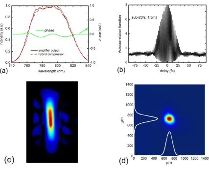
∼3.5 nm in the first stage of the CPA pump laser consisting of an Yb:glass regenerative ampli-fier (RA) followed by a second Yb:YAG multipass ampliampli-fier both pumped with laser diodes, as presented in Ref. [71, 72]. After the amplifiers the pulses are recompressed in a grating com-pressor composed of diffraction gratings identical to that used in the stretcher. The design of this pulse compressor was discussed in section 2.2.3. Owing to the unavailability of the final amplifier stages, which were under construction during this work, we used only a single G1 (at
Chapter 2. Seed generation and stretcher-compressor setup for the CPA pump laser
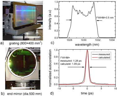
Figure 2.10: Picture of the large grating (a), and end mirror mirror (b) assembly used in the compressor. (c) Spectrum of the amplified pulse at the input of the compressor. (d) Measured and calculated autocorrelation functions of the compressor output pulse.
dimensions of 800×400 mm, assembled on a home-made† rotation stage (Fig. 2.10(a)) which can provide a resolution of ∼0.003◦ for the relational motion about the vertical axis, was po-sitioned at a distance of 6.1 m along the wavelength componentλ0=1030 nm. The diffracted
beam after the second grating were redirected for the second pass by a 500-mm diameter end mirror (Fig. 2.10(b)) placed at a distance of∼3 m from the second grating. The gratings were further aligned to correct the pulse-front tilt due to the angular chirp, resulting from any relative angle between the two gratings as discussed in Sec. 2.2.4, using a home-built inverted-field au-tocorrelator [95]. This device can detect the pulse-front tilt in both the horizontal as well as in the vertical planes of the beam propagation axis, thereby provided a tool for the correction of the relative grating angle in these planes as discussed in Sec. 2.2.4.
The calculations of the dispersion introduced by the in-between amplifier by taking into ac-count the physical thicknesses of all the optical materials (cf. Appendix A) revealed an additional amount of+2.76×10⁵fs2of GDD and+3.30×10⁵fs3of TOD for the stretched amplified pulse.
2.3. Conclusion
The extra GDD can be compensated by slightly increasing the grating separation in the compres-sor by∼3 mm. The resulting uncompensated TOD of+2.52×10⁶ fs3can be adjusted by fine tuning the grating separation and angle of incidence, as shown in Fig. 2.7.
The compressed pulses were characterized by a home-built single-shot second-order autocor-relator with a tuning window of 6 ps and a pixel resolution of 22 fs. This device is designed to measure 700 fs pulses with an accuracy of∼6%. Under optimum conditions, we were able to get a FWHM of 1.28±0.04 ps, averaged over 100 successive shots, of the autocorrelation function of the compressed pulse. In order to estimate the width of the compressed pulse, we calculated the TL pulse duration as well as the autocorrelation function from our measured spectrum. A deconvolution factor of 1.3518 was inferred from these calculations. Using this factor we can obtain a realistic estimate for our compressed pulse duration which turns out to be 947 fs, close to the calculated TL of 806 fs, with a measurement uncertainty of 40 fs. The compressor provides an overall thoughput of∼66%, delivering the compressed pulses with an energy of 200 mJ. The probable reason for the difference between TL and measured pulse durations is the uncompen-sated higher-order dispersion of the amplified pulse, which can be improved by the installation of an acousto-optic programmable dispersive filter (AOPDF [97]). Another possibility is the spatio-temporal coupling caused by B-integral issues when the compressed pulse propagates in several meters air after the last grating.
2.3
Conclusion
ex-Chapter 2. Seed generation and stretcher-compressor setup for the CPA pump laser
Chapter
3
Chirped pulse amplification of the oscillator
output
The generation of a broadband spectrum appropriate for seeding the main OPCPA chain of PFS (700-1400 nm) is based on intensity dependent nonlinear effects, such as the production of a supercontinuum extending up to the near-infrared or idler generation using non-collinear optical parametric amplification. The details of these techniques will be discussed in the next chapter. Since such processes demand an intensity, and hence energy, that cannot be delivered by the few-nJ scale output of the master oscillator introduced in Chapter 2, a CPA scheme needs to be used. We amplified the part of the oscillator output which was dedicated for the OPCPA seed using a CPA-based Femtopower amplifier (Femtolasers GmbH). The commercial system comprises a double-prism pair compressor for compression of the amplified pulses.
In this chapter we discuss the drawbacks of pulse compression when only a prism com-pressor is used. A hybrid pulse compression (HPC) technique, i.e. a combination of high-dispersive negative mirrors (HDM’s) and prism compressor, is demonstrated to cope with these challenges [49, 98]. We also present modification in the calculations of the dispersion of a double-prism compressor previously reported by Cheng et al., [50]. Here, the impact of the beam diameter of incident beam and bulk material of the prisms on the effective dispersion of the prism compressor is demonstrated. Moreover an alternative technique for the compression of TW-level pulses using a novel high-dispersive mirror compressor is presented, providing re-markable simplifications in dispersion management.
3.1
Femtopower amplifier upgrade
3.1. Femtopower amplifier upgrade
acousto-optical dispersive filter [97] (DAZZLER, FASTLITE) and a multi-pass Ti:sapphire am-plifier [99]. The seed pulse in this setup is dominantly stretched by the material dispersion of SF57 glass and DAZZLER crystal (TeO2), contributing positive chirp to the amplifier
in-put pulse. Different optical media in the amplifier such as polarizers, Pockels cell, Ti:sapphire crystal etc. (cf. Table 3.1) also contribute to the dispersion of the amplified pulse. The TOD mirrors and programmable higher-order dispersion from the DAZZLER are used for fine correc-tion of spectral phase during recompression of the amplified pulse. The amplifier is a 10-pass system operating at 1 kHz, pumped at 527 nm by the frequency-doubled output of a Nd:YLF laser (DM30, Photonics Industries). It delivers 2 mJ pulses with a FWHM spectral bandwidth of 62 nm centred at 790 nm. The output pulses are subsequently compressed in a LAK16 double-prism pair compressor. Using only the double-prism compressor for correcting the spectral phase of
Figure 3.1: Schematics of the Femtopower amplifier and hybrid pulse compressor. BS: beam splitter; TOD mirror: mirrors with third-order dispersion; HDM: high dispersive mirrors.
the mJ-scale femtosecond pulses results in self-phase modulation (SPM) in the prism material and consequently spectral narrowing as shown later in Fig. 3.5(b). An HPC technique, in which the amplified pulses are recompressed using HDM’s in combination with the prism compressor, was developed to resolve this problem. In the scheme, the chirp of the input pulses is partially corrected by the negative group velocity dispersion of the prism compressor. The pulses pass through the prism material at reduced intensity, hence avoiding the SPM, by carrying some chirp and are finally compressed by the HDM’s.
Chapter 3. Chirped pulse amplification of the oscillator output
the required separation for the pulse compression. In these calculations we evaluate the GDD as a function of angular frequency (or wavelength) which allows us to calculate the coefficients of dispersion, hence the spectral phase (cf. Eq. 2.4), of the pulse at any arbitrary angular frequency (or wavelength). Finally, the arrangement for the HPC is discussed.
3.1.1
Dispersion calculation of the amplified stretched pulse
As discussed in the previous section, the input pulses of our amplifier setup are temporally stretched by the material dispersion of different optical components. In this section we review a few formulae for calculating this dispersion, and hence the chirp of the amplified pulses in our setup.
The GDD has been defined as the coefficient of Taylor expansion of frequency-dependent spectral phase Φ(ω) in Eq. 2.4. For an optical material with a thickness li and
frequency-dependent refractive indexni(ω)it can be written as [88]
∂2Φi(ω) ∂ ω2 =
∂2
∂ ω2 ω
cni(ω)·li
(3.1)
Differentiating twice Eq. 3.1 with respect toω we have
∂2Φi(ω)
∂ ω2 =
li c
2dni(ω) dω +ω
d2ni(ω)
dω2
. (3.2)
Substituting dni(ω) dω =
−λ2 2πc
dni(λ) dλ and
d2n
i(ω) dω2 =
λ3
(2πc)2
2dni(λ) dλ +λ
d2n
i(λ) dλ2
in Eq. 3.2 we obtain
∂2Φi(ω)
∂ ω2 = λ3
2πc2·li
d2ni(λ)
dλ2 . (3.3)
Equation 3.3 describes the GDD introduced by an optical material as a function of wavelength. Summation over all the optical materials from our amplifier setup would yield the cumulative GDD of the amplified pulses, as follows
GDD|amp.= λ
3
2πc2
∑
ilid
2n i(λ)
dλ2
. (3.4)
The calculated GDD of the amplified pulse in our setup is shown in Fig. 3.2(a). The GDD curve is obtained by taking into account the physical thicknesses of all the optical materials in our setup (cf. Table 3.1). It also includes an additional programmable dispersion of+6800 fs2 (GDD) from the DAZZLER for the whole range of 735–845 nm of the amplified spectrum (see measured spectrum later in Fig. 3.8(a)). The calculated coefficients of dispersion of the amplifier output pulses at λ0=790 nm are: D2 = +41500 fs2, D3 = +22000 fs3 and D4=−7000 fs4
(fourth-order dispersion: FOD), for definition see Eq. 2.4. The group delay (i.e. GD= ∂Φ(ω)
∂ ω ),
3.1. Femtopower amplifier upgrade
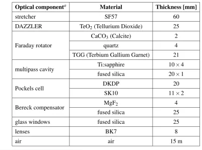
Table 3.1: Optical thicknesses of different components of the laser amplifier in our setup
Optical componenta Material Thickness [mm]
stretcher SF57 60
DAZZLER TeO2(Tellurium Dioxide) 25
Faraday rotator
CaCO3(Calcite) 2
quartz 4
TGG (Terbium Gallium Garnet) 21
multipass cavity Ti:sapphire 10×4 fused silica 20×1
Pockels cell DKDP 20
SK10 11×2
Bereck compensator MgF2 4
fused silica 25
glass windows fused silica 25
lenses BK7 8
air air 15 m
aThe significance of most of these components can be found in [99].
Fig. 3.2(b). This curve provides a direct estimate of the relative time difference between dif-ferent spectral components of the pulse. From this figure it can be deduced that the amplifier output pulse in our setup, with its spectrum ranging from 735–845 nm, extends up to∼15 ps.
3.1.2
Dispersion of the prism compressor
The schematic model of the double-prism pair compressor is shown in Fig. 3.3. Four prisms with an identical apex angleαpare arranged for the angle of minimum deviation for the central
wavelengthλ0. θi andϕi(i=1· · ·8) denote the respective angles of incidence and refraction at
the eight interfaces. The chirp introduced by the prism compressor is a cumulative effect of the angular dispersion and material dispersion [100]. The effective GDD of the prism compressor can be written as follows
GDD|e f f = d
2 Φ(ω)
dω2 ang + d 2 Φ(ω)
dω2 mat . (3.5)
Most of the optical materials exhibit positive GDD, in the spectral range of our interest (cf. Fig 3.2(a)), whereas the angular spread (refraction) after the prisms results in negative GDD.
Chapter 3. Chirped pulse amplification of the oscillator output
Figure 3.2:a) Calculated GDD, and b) GD of the stretched amplified pulse after the multi-pass laser amplifier
adapted by Fork et al. [47], and by Cheng et al. [50] for the so-called principle arrangement (see Appendix B). In this arrangement the spectral components atλ0travel through the vertices of all
prisms i.e. along the curveBCDEF (Fig. 3.3(a)). d2Φ(ω)
dω2
ang
=2· λ
3
2πc2·
d2P(λ)
dλ2 , (3.6)
where P(λ) denotes the total optical path length (cf. Appendix B), whileΦ(ω)is the spectral
phase delay introduced by the angular dispersion, and the factor 2 is for double pass configura-tion. For the apex-to-apex distances of `1, L, and`2between the prismsP1-P2,P2-P3, andP3-P4,
respectively d2P(λ)
dλ2 can be calculated as [50]
d2P(λ)
dλ2 = (`1+`2) (
d2ϕ2(λ)
dλ2 sin[θ1−ϕ2(λ)]−
dϕ2(λ)
dλ 2
cos[θ1−ϕ2(λ)]
) +
L
(
d2ϕ4(λ)
dλ2 sin[ϕ4(λ0)−ϕ4(λ)]−
dϕ4(λ)
dλ 2
cos[ϕ4(λ0)−ϕ4(λ)]
) ,
(3.7)
where
ϕ2(λ) =arcsin
np(λ)sinαpcos
arcsin
sinθ1
np(λ)
−cosαpsinθ1
, (3.8)
ϕ4(λ) = arcsin
np(λ)sinαpcos
arcsin
sinΓ(λ)
np(λ)
−cosαpsinΓ(λ)
, (3.9)
andΓ(λ) =θ3=2θ1−ϕ2(λ).
Equation 3.7 is only valid for the principle configuration for which the spectral components at λ0 travel through the vertices of all prisms, i.e. along the curve BCDEF (Fig. 3.3(a)), as
discussed in Ref. [50]. In this arrangement, the wavelengths smaller thanλ0(denoted byλs) are
3.1. Femtopower amplifier upgrade
Figure 3.3: Schematic diagram of the double-prism compressor. The optical construction is adapted from [50].
to accommodate theλs components, the prism P2, hence P1 (being paired), is translated along
axis O, as shown in Fig. 3.3(b). Similarly, the prism pair P3-P4is shifted parallel to the axisO0
to capture theλ`wavelengths. The third such displacement of both prism pairs is caused by the
spatial beam profile (beam diameter) of the incoming pulse. These effects contribute material dispersion to the input pulse which is calculated as follows.
The GDD introduced by the prism material can be written as (recalling Eq. 3.3)
d2Φ(ω)
dω2
mat
=2· λ
3
2πc2·
Lmd
2n p(λ)
dλ2 , (3.10)
whereLmis the total optical material length for a single pass through all the four-prisms (P1–P4)
corresponding to the wavelengthλ0. The factor 2 in Eq. 3.10 is for the double-pass configuration,
as adapted in Eq. 3.6. Lm can be subdivided into the individual contributions from each prism pair as
Lm=Lm12+Lm34, (3.11)


![Figure 2.5: The schematic layout of the CPA-seed stretcher with 4-times folding geometry, i.e.eight reflections off the grating as sketched by an optical ray-tracing software: RAYTRACE [91].(a) Beam propagation in the xz-plane](https://thumb-us.123doks.com/thumbv2/123dok_us/8092859.1350787/31.595.115.507.139.460/schematic-stretcher-geometry-reections-sketched-software-raytrace-propagation.webp)