Design and Implementation of Area-Efficient Dual-Mode
Double Precision Floating Point Division
A. Sanjeev Kumar
, K. Shyam
,
Snigdha Kamala
[email protected] , [email protected] , [email protected]
1 PG Scholar, Dept of ECE, Kommuri Pratap Reddy Institute of Technology, Hyderabad, Telangana, India 2 Assistant Professor, Dept of ECE, Kommuri Pratap Reddy Institute of Technology, Hyderabad, Telangana, India 3 Assistant Professor, Dept of ECE, Kommuri Pratap Reddy Institute of Technology, Hyderabad, Telangana, India
Abstract: Floating point division is a center number-crunching broadly utilized as a part of logical and
building applications. This paper proposed
engineering for twofold precision floating point division. This engineering is intended for double mode usefulness, which can either register on a couple of twofold precision operands or on two sets of single precision operands in parallel. The engineering
depends on the arrangement development
multiplicative approach of mantissa calculation. For this, a novel dual mode Radix-4 Modified Booth multiplier is planned, which is utilized iteratively in the design of double mode mantissa calculation. Other key parts of floating point division stream, (for example, driving one-identification, left/right unique shifters, adjusting, and so on.) are additionally re-intended for the double mode operation. The proposed double mode engineering is orchestrated utilizing UMC 90nm innovation ASIC execution. Two forms of proposed design are exhibited, one with single stage multiplier and another with two phase multiplier. Contrasted with an independent twofold precision division design, the proposed double mode engineering requires 17% to 19% additional equipment assets, with 3% to 5% period overhead. In contrast with earlier craftsmanship on this, the proposed design out-performs them regarding required area, era and throughput.
Keywords: Arithmetic, ASIC, configurable
architecture, dual-mode division, floating point division, multi-precision arithmetic.
I.INTRODUCTION
Floating point number juggling (FPA) structures experienced critical progression by logical research in the previous a very long while. FPA is a fundamental element of a vast arrangement of logical and designing space applications. To help the
application exhibitions, the FPA models created from scalar to vector structures in different handling stages. Varieties of single precision and twofold precision figuring units are being utilized for floating point vector preparing. The ebb and flow look into work is pointed towards bound together vector-preparing units. That is, rather than having separate vector varieties of single precision and twofold precision, it can have a variety of configurable floating point number juggling pieces. Where each of these configurable pieces can process either a twofold precision or two parallel single precision calculations. This configurable piece exhibit course of action can prompt critical area change, while giving the required execution.
Our examination work is centered around the engineering plan of configurable floating point number-crunching squares. This paper is centered around the outline of configurable double mode twofold precision division number juggling unit. Floating point (FP) division is a center calculation required in a huge number of utilizations. FP division is a mind boggling number juggling operation which requires bigger area with poor execution than the essential number-crunching operations (adder, subtractor and multiplier). In perspective of expansive area prerequisite of division number-crunching per unit of calculation, this work is gone for a multi-precision double mode engineering for this calculation. The proposed design can be arranged either for a twofold precision or two parallel (double) single precision division calculations, and in this manner named as DPdSP division engineering.
[6], which are speedier than the digit-repeat strategies like SRT. A nitty gritty dialog on different technique for FP division can be looked for from [2], [7]. The mantissa division in multiplicative strategy depends on the use of number multipliers, which adds to their execution contrasted with conventional digit repeat technique (like SRT technique). Further, arrangement development technique gives an equipment effective design to a given precision necessity [5]. The arrangement development strategy helps in diminishing the memory necessity, and other related equipment assets contrasted with NR and GS strategies. In view of the at present proposed double mode division engineering utilizing arrangement development approach, other multiplicative division strategies (NR and GS techniques) can likewise be intended for double mode design, be that as it may, they should be investigated for their possibility in configurable double mode design, which is a piece of our future examination.
A novel double mode Radix-4 Modified Booth multiplier is intended with the end goal of mantissa division, which has insignificant area and execution overhead finished single-mode multiplier. It depends on the Radix-4 Modified Booth Algorithm [8] which is overhauled here, to suit double mode preparing. Likewise, since the hidden number multiplier in mantissa division unit has the significant cost as far as required area, an iterative engineering is proposed utilizing a solitary 1-organize whole number multiplier, to accomplish area effectiveness. Moreover, to enhance the execution, an engineering with 2-arrange whole number multiplier is likewise proposed, which additionally shows the utilization of multi-organize multiplier in the proposed double mode design.
The proposed DPdSP division structures are intended for typical and sub-ordinary computational help, which also incorporate the remarkable case taking care of and preparing. It can create dedicated adjusted outcomes with round-to-closest adjusting, both in twofold and single precision. Steadfast adjusting is reasonable for a substantial arrangement of utilization, nonetheless, the right adjusting can be incorporated utilizing leftover portion strategy for multiplicative division philosophy [2], [9], which requires preparing of one more increase. All the significant building
squares (like mantissa division, driving one-location, dynamic right/left moving, adjusting) are outlined and enhanced for the productive double mode preparing. A solitary mode twofold precision division engineering, in light of comparative computational stream, is likewise intended for examination reason, to exhibit the relative advantages of double mode division design.
A few papers have proposed FP models on the possibility of configurable multi-precision floating point number juggling handling. The larger part of earlier works are engaged towards the adder models [10]– [14] and multiplier designs [15]– [17]. Isseven et al. [18] is the main accessible work on double mode division number juggling which exhibited an iterative double mode design for division, in view of the Radix-4 SRT (digit repeat) division strategy, and is pointed just for typical configuration of calculation. The algorithmic thought of current work is introduced by Jaiswal et al. in [19], with a solitary cycle fully unrolled plan for the outline reason, which requires substantial area with poor execution. The present work is based upon the [19], with intriguing and down to earth approach for DPdSP division design, included with some novel structural changes.
The principle commitments of this work can be summarized as takes after:
• Proposed double mode DPdSP division models with ordinary and sub-typical computational help, alongside all the outstanding case taking care of. These structures can be progressively designed either for a twofold precision division or two parallel single precision divisions.
• A novel double mode Radix-4 Modified Booth multiplier engineering is proposed, which turns into the base of the proposed double mode mantissa division design.
• All the key segments of the FP division stream are intended for proficient double mode usefulness with insignificant overhead.
• Proposed structures are fully pipelined, and composed in an iterative mold for area-productivity.
Floating point division:
representations are slower and less accurate than fixed-point representations, but can handle a larger range of numbers. Because mathematics with floating-point numbers requires a great deal of computing power, many microprocessors come with a chip, called a floating point unit (FPU ), specialized for performing floating-point arithmetic. FPUs are also called math coprocessors and numeric coprocessors. Floating-point representation has a complex encoding scheme with three basic components: mantissa, exponent and sign. Usage of binary numeration and powers of 2 resulted in floating point numbers being represented as single precision (32-bit) and double precision (64-bit) floating-point numbers.
IEEE-754 Floating-point Representation Standards (Single precision and double precision)
II. BACKGROUND
The basic computational stream for FP division math is exhibited in Algorithm 1. This calculation is appropriate for both ordinary and sub-typical handling. It likewise incorporates the uncommon case taking care of and preparing. FPA execution includes registering independently the sign, example and mantissa part of the operands, and later consolidating them subsequent to adjusting and standardization [20]. In the present work, all phases of the above computational stream are intended to help double mode operations.
A. Underlying Mantissa Division Method
The mantissa division is the most complex piece of the FP division number juggling execution. The algorithmic procedure for this calculation is examined here. It depends on the arrangement extension technique for division, as takes after. Give m1 a chance to be the standardized profit mantissa and m2 be the standardized divisor mantissa, and after that q, the mantissa remainder, can be processed as:
Here, the divisor mantissa m2 is divided into two sections as a1 (with W + 1-bit), and a2 (every residual bit) as underneath.
By using Taylor Series expansion,
pre-processed estimation of a1−1 can be gotten to from a pre-accumulated up table to play out the whole calculation; which is effectively feasible in equipment execution. The pre-registered estimation of a1−1 goes about as an underlying guess for m1−2, which additionally enhanced with residual calculation in (2). Here, the size W (bit width) of a1 (here, the shrouded "1" bit put in a1 isn't checked, as it stays as steady an incentive in the standardized configuration) decides the span of memory (for look-into table to store a1−1) and the quantity of terms from the arrangement development, to play out the calculation for a given precision. The quantity of terms (N) (with a given W) for a given precision prerequisite (2−P) can be dictated by following imbalance:
Where, EN is error caused by all the disregarded terms in (2). For greatest error, numerator of (3) ought to be most extreme with the base an incentive for numerator. Thus, for most skeptical estimation (for least denominator, let (1 + a1−1a2) ≈ 1, and for maximum numerator let a1−1 = 1),
Hence, it can be seen that for a given precision prerequisite, increment in W would decrease the required number of terms N and bad habit verse. Here, the estimation of W decides the measure of memory (to store the pre-figured a1−1), and N decides the measure of other equipment (multipliers, adders, subtractors). For twofold precision necessity (P = 53), a minor departure from estimation of W and required number of terms (N) is appeared in Table-I.
TABLE I
LOOK-UP TABLE ADDRESS SPACE AND REQUIRED NUMBERS OF TERMS (N), FOR A GIVEN W, NEEDED FOR DOUBLE PRECISION
ACCURACY
For a decent harmony amongst W and N, bit width of W = 8 for a1 is chosen, which requires 7 terms (up to a1−7a26) for twofold precision. Thus, it needs 3 terms (up to a1−3a22) for single precision necessity with W = 8. The particular remainder condition for twofold and single precision are as per the following: For twofold precision:
For single precision:
Here, it can be effortlessly observed that the (6) resembles a subset of (5). Along these lines, both can have the same computational stream. Likewise, (5) and (6) are encircled in such way, so that, the (5) goes about as a super-arrangement of the two conditions as takes after:
This fascinating element of (7) shapes the premise of sharing equipment assets to proficiently display the double mode design for mantissa division calculation, which is fit for preparing either a DP mantissa or two SP mantissa divisions.
composed, which is utilized iteratively for whole calculation of (7). The full mantissa width increase is utilized (for DP and also double SPs) for all the calculation, which helps in safeguarding the precision of the considerable number of terms [2], [9].
Subsequently, utilizing arrangement extension technique, the mantissa division required after advances:
• Partition divisor mantissa (m2) in two sections, a1 and a2.
• Store the pre-registered estimation of a1−1 in look-into table.
• Based on required precision, decide the quantity of arrangement development terms to process. • Compute for mantissa remainder utilizing the estimation of a1−1, a2 and m1 in settled articulation.
III. PROPOSED DPDSP DIVISION ARCHITECTURE (WITH 1-STAGE
MULTIPLIER)
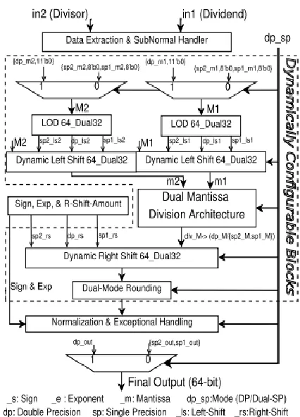
The proposed architecture is shown in Fig. 1. It is composed of three pipelined stages. The subtle elements of each stage engineering are talked about beneath in following subsections one-by-one. Two 64-bit operands, one profit (in1) and another divisor (in2) are the essential contributions alongside the mode-control flag dp_sp (twofold precision or double single precision). Both of the info operands either contains DP operands (as whole 64-bit combine) or two parallel SP operands (as two arrangements of 32-bit match), as appeared in Fig. 2.
Fig. 1: DPdSP Division Architecture.
Fig. 2: DPdSP Input Output Format.
A. First-Stage Architecture
Fig. 3: DPdSP Division: Data Extraction.
These take the essential operands and concentrate the signs (sp1_s1, sp1_s2, sp2_s1, sp2_s2, dp_s1 and dp_s2), types (sp1_e1, sp1_e2, sp2_e1, sp2_e2, dp_e1 and dp_e2) and mantissas (sp1_m1, sp1_m2, sp2_m1, sp2_m2, dp_m1 and dp_m2) segments for twofold precision and both single precision, in view of their standard configurations as appeared in Fig. 2.
The information/yield encoding depends on the IEEE standard binary arrangement [20]. The sub-typical (_sn) taking care of and extraordinary checks calculations are appeared in Fig. 4. As the 8 MSB of DP example cover with SP-2 type,
Fig. 4: DPdSP Division: Sub-Normal and Exceptional Handling.
The checks for sub-typical, endlessness and NaN (Not-A-Number) have been shared among SP-2 and DP, as appeared in Fig. 4. It likewise performs checks for partition by-zero (_dbz) and zero (_z), and have been shared among DP and both SPs. After information extraction and excellent checks, a bound together arrangement of mantissa (M1 and M2) is produced utilizing two MUXes (as appeared in Fig. 1). In view of the method of operation, these contain the mantissa either for DP or for both SPs. This unification of mantissas helps in planning a tuned datapath handling for later stage calculation, which brings about proficient asset sharing.
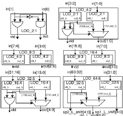
Fig. 5: DPdSP Division: Dual-Mode LOD.
The following two units, the main one-indicator (LOD) and dynamic left shifter, in this stage perform ordinary handling. They bring the sub-ordinary mantissa (assuming any) into the standardized arrangement. Initially it registers the measure of left-move utilizing double mode LOD and after that left-moves the mantissa with the double mode dynamic left shifter. The relating left moving sum is additionally balanced in the type. The design for double mode LOD is appeared in Fig 5.
The double mode LOD is composed in a various leveled mold, utilizing an essential building square of 2:1 LOD which comprises of an AND, an OR, and a NOT gates. The last 64:6 LOD unit comprises of two 32:5 LOD units, which work separately for SPs (on each 32-bit parts of information mantissa), and their yield blend gives the left-moving add up to DP mantissa. The whole assets in double mode LOD unit are shared among DP and SPs handling, and it costs no overhead contrasted with just DP LOD.
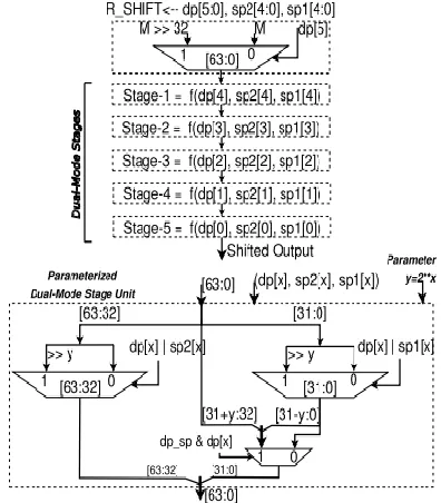
The brought together mantissas (M1 and M2) are then sustained in to the double mode dynamic left shifter alongside the comparing left-moving sum from LOD units (as appeared in Fig. 1).
design for double mode dynamic left shifter is appeared in Fig. 6.
Fig. 6: DPdSP Division: Dual-Mode Dynamic Left Shifter.
It is a 6-arrange barrel shifter unit, in which initially organize is a solitary mode unit, and the 5 remaining stages are dualmode units. The principal organize unit is a straightforward left-move barrel shifter which performs moving just in twofold precision mode, in light of the MSB of DP move bits. The double mode organize is introduced in bland shape in Fig. 6, and it can be reached out for any size double mode plan. It works either for DP or for double SP dynamic left moving. A double mode arrange contains two multiplexers for each 32-bit pieces, which move their information sources in view of the comparing moving bits (both of DP or both SPs). The moving sum for a given double mode arrange is given by y = 2x, where "x" is the moving bit position for that stage. The double mode organize likewise contains a multiplexer which chooses between 32-bit MSB moving yield or their blend with essential 64-bit contribution to the stage, in view of the genuine dp_sp and relating moving bit of DP left move. But this multiplexer, the double mode stages carries on like two separate 32-bit barrel shifter, which are developed to help double mode left moving operation.
After left moving, mantissas shows up into standardized frame m1 and m2, as appeared in Fig. 1. In the following unit in this phase of division engineering, the 8-bit (after decimal point position)
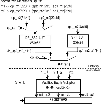
MSB part(a1) of standardized divisor mantissas (m2) are utilized to get the pre-figured beginning estimate of their opposite, as talked about in the Section II. It is appeared in the principal organize some portion of Fig. 7. Two look-into tables are utilized here. One is shared for DP and SP-2 introductory guess with size of 28×53 (13.5 KB), which goes about as 28×53 for DP and 28×24 for SP-2. Other look-into table with size of 28 × 24 (6 KB) works for SP-1 as it were. In this way, it requires a sum of (28 × (53 + 24)) 19.7 KB memory to store introductory approximations of a1−1.
Fig. 7: DPdSP Dual Mode Mantissa Division Architecture
B. Second-Stage Architecture
Fig. 8: DPdSP Division: Sign, Exponent and Right Shift Amount.
The sign calculation is a basic XOR operation among both info operands sign bits. The related example calculation is the distinction of profit (in1) type and divisor (in2) type, with appropriate BIASing and the change of mantissa left move sum (LSA):
On the off chance that above calculation restores a negative esteem (i.e. at the point when the compelling divisor type (Exp_in2 − LSA_in2) is bigger than the successful profit example (Exp_in1 − LSA_in1) while including BIASing), the resultant mantissa division result requires to be moved appropriate by right-move sum (RSA). This will comes about into a subnormal yield.
Every one of these calculations is done independently for DP and both SPs.
The mantissa calculation is the most complex piece of the floating point division number juggling. Here, its related design incorporates the brought together and double mode execution of (7). As appeared in Fig. 7, the underlying backwards estimation of divisor mantissa is brought in first phase of design. The rest of the calculation is worked around a double mode booth multiplier, in an iterative mold. A double mode limited state machine (FSM) is outlined which chooses the powerful contributions for multiplier in each state and which will be talked about soon after the depiction of double mode multiplier design.
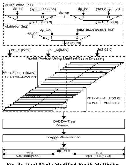
1) Dual-Mode Radix-4 Modified Booth Multiplier Architecture:
The engineering for the double mode Booth multiplier is appeared in Fig. 9. The engineering depends on the Radix-4 Modified Booth Encoding, which lessens the quantity of incomplete items at most to ( n2 + 1) [8]. Here, it is a 54-bit number multiplier (for DP preparing), which is additionally intended to process two parallel arrangements of 24-bit unsigned operands (for two SPs handling) duplication. Truth be told it can process two parallel arrangements of 26-bit unsigned operand increase, utilizing whole 14 incomplete results of PP1 for first set and whole PP2 for second set operand, without ruining each other. Be that as it may, here it is exhibited for current prerequisite as it were.
Fig. 9: Dual-Mode Modified Booth Multiplier Architecture.
multiplicand" or "SP-2 multiplicand operand at the MSB side." While, the multiplier input (in2) contains multiplier operands either for DP, or for both SPs with 6-bit zeros in the middle of (see top segment of Fig. 9). Correspondingly, two-arrangements of fractional items (PP1 and PP2) are produced. Incomplete items PP1 are the aftereffect of in1_t1 and in2, and PP2 is gotten from in1_t2 and in2. In DP method of operation all the halfway results of PP1 and PP2 all things considered deliver the increase result. Though, in double SP mode, initial 13 fractional results of PP1 (i.e. PP1-SP1, with all MSBs past 25th-bit are zero) comes about for SP-1 and, the last 13 halfway results of PP2 (i.e. PP2-SP2, with all the LSBs till 30th-bit are zeros) comes about for SP-2, while the fourteenth and fifteenth halfway items will be invalid, containing every one of the zeros. Here, the sources of info in1_t1, in1_t2 and in2 are constructed so that, in double SP mode handling the single precision halfway items (PP1-SP1 and PP2-SP2) and their diminishment don't cover (Fig. 9), and deliver two unmistakable outcomes for SP-1 and SP-2 duplication, separately.
In this way, the sum of every single halfway item will create item for DP operands in DP-mode or for both SPs in dualSP mode. A DADDA-tree of 8 levels is intended to pack all the incomplete items into two operands, which are additionally included utilizing a parallel-prefix Kogge-Stone last adder. The last item contains either DP or double SP comes about as appeared in Fig. 9. In this manner, the few key alteration in the Modified Booth increase stream prompts a novel double mode working. The structure of the fractional item age in displayed double mode Modified Booth multiplier, regarding equipment necessities, is like the contemporary Modified Booth multiplier. In any case, how a similar structure is changed (by incorporation of info operands multiplexing, and fractional item assignments as needs be) for double mode handling, is the curiosity of proposition. Contrasted with the contemporary Modified Booth multiplier, the proposed double mode Modified Booth multiplier requires just three 2:1 MUXs as an area overhead, which are required for the info operands multiplexing.
2) Dual-Mode Iterative Mantissa Division
Architecture:
The mantissa division is planned in an iterative design to have an area proficient engineering. The engineering depends on the bound together execution of (7), which can process either a DP mantissa division or two parallel SPs mantissa divisions, with help of above examined double mode changed Booth multiplier. Condition (7) is recorded underneath for a simple reference
Here, m1 is the standardized profit mantissa; and m2 is the standardized divisor mantissa, where m2 is divided into a1 (initial 8-bit ideal to the decimal point) and a2 (every outstanding bit ideal to the a1).
Both, m1 and m2, are showing up in the standardized arrangement from first-organize handling, and they contain either DP mantissas (dp_m1[52 : 0] and dp_m2[52 : 0]) or both SPs mantissas (sp1_m1[23 : 0], sp1_m2[23 : 0], sp2_m1[23 : 0] and sp2_m2[23 : 0]), as appeared in Fig. 7. Here, for the simplicity of understanding the later portrayal, different blends of terms in above bound together condition are recorded as takes after:
The limited state machine (FSM) is appeared in Fig. 10. For DP preparing it experiences every one of the states, though for double SP it skips states S4 and S5 which perform just DP related calculations. The determination of bits for a term depends on the position of decimal point and preparing mode. For the most part, for DP mode, the augmentations are done in 54-bit (adequate for its precision prerequisite) and include/sub are performed in 64-bit (to save precision), though, for dual SPs, the increases are done in 24-bit and include/sub are performed in 32-bit.
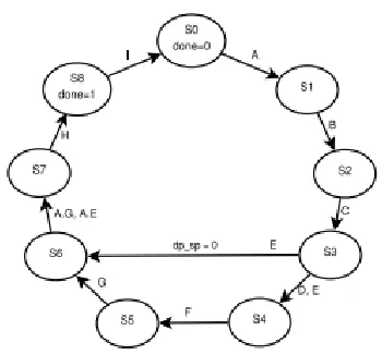
Fig. 10: DPdSP Dual-Mode Iterative Mantissa Division FSM
In state S0 of FSM, the profit mantissas are connected to in1_t1 and in1_t2 and, a1−1 is connected at in2, either for DP or both SPs. This creates A = m1a1−1 in the following state. In state S1, a2 is connected at in1_t1 and in1_t2, either for DP or both SPs, and in2 stays with a1−1. This produces B = a1−1 a2 in the following state. The state S2 applies past increase yield (B = a1−1a2) to all the multiplier contributions to wanted organization, in light of the method of operation, which produces C = a1−2a22 in the following state. Further, the CD P, the DP type of C, is connected to all contributions, in the state S3, as the relating yield is implied just for DP preparing, which produces DD P = a1−4a24 in the following state. State S3 additionally forms the term E = B − C. All contributions of multiplier are set to zero in state S4, and this state forms the term FD P. The state S5 applies E, in DP organize, at in1_t1 and in1_t2 and, FD P at in2, and this produces G in the following state. The following state S6 applies either G or "E in SP organize just" at the multiplicand inputs in1_t1 and in1_t2 and, An at the multiplier input in2, which produces AG or AE in the following state. In state S7, in view of the method of operation, the term H will be both of AG or AE. Lastly, the last term I = A − H is registered in state S8, with the declared done flag. The term I contains the mantissa remainder either for DP (overall) or for two SPs (in each 32-bit parcel).
mantissa division FSM requires 14 54-bit 2:1 MUXs as an overhead.
C. Third-Stage Architecture
The third phase of the FP division engineering relates to the calculations of stages 6,7 and 8 of the Algorithm 1. In this stage, for the instance of example undercurrent (if profit type is littler than the divisor type), mantissa division remainder is first process for the dynamic right moving. This is trailed by the double mode adjusting of the remainder mantissa, and after that it experiences standardization and uncommon case handling.
1) Dual-Mode Dynamic Right Shifting:
The design for double mode dynamic right shifter is appeared in Fig. 11. The right-move sum (Fig. 8) and mantissa remainder goes about as essential contributions to the double mode dynamic right shifter. Like the double mode dynamic left shifter engineering, this unit has 6-organizes, the main stage is single-mode for DP handling just, and 5 remaining stages are double mode in nature. The non specific engineering for double mode organize is appeared in Fig. 11. The best two MUXs work for each SP mantissa remainder dynamic right moving, which are consolidated by the third MUX to deliver the DP mantissa dynamic right moving.
Fig. 11: DPdSP Dual-Mode Dynamic Right Shifter.
2) Dual-Mode Rounding:
The proposed double mode engineering is composed with steadfast adjusting, utilizing round-to-closest strategy. It is involved two stages, first the unit-finally put (ULP) calculation and afterward ULP expansion with remainder mantissa. ULP calculation depends on the adjusting position bit, Guard-bit, Round-bit and Stickybit. The adjusting position is dictated by the MSB of the remainder mantissa. Watch and Round bits are by the adjusting position bit at LSB side, while all the rest of the LSB bits of mantissa remainder create the Sticky-bit.
The ULP-calculation is done independently for DP and both SPs remainders, and each of them requires few logic-gates for this reason, as appeared in Fig. 12. Though, the ULP-expansion with remainder mantissa is shared among DP and both SPs. As, mantissa remainder contains either DP or double SPs remainders, its ULP-expansion is shared as appeared in Fig. 12.
It is finished utilizing two 32-bit incrementer, which independently acts like a SP ULPadder, be that as it may, their blend (by spreading carry) likewise performs for DP ULP-expansion. Consequently, the double mode adjusting requires few logic-gates (for SPs ULP-calculation) and two 1-bit 2:1 MUXs (for ULP-expansion) as an overhead finished singlemode DP adjusting.
The right adjusting in multiplicative based division strategies requires the calculation of leftover portion to create the Sticky-bit [2], [9]. The rest of requires one more augmentation and a subtraction, which would require two more states in the FSM with 1-arrange multiplier, and 3 more states in FSM with 2-organize multiplier. These can be incorporated in light of the necessity. Likewise, like the round-to-closest adjusting strategy, different techniques can likewise be incorporated in light of the necessity. As, the ULP calculation can't be shared among DP and SPs and it requires little logical calculation, it is introduced for round-to-closest strategy, which is most generally utilized.
3) Final Processing:
The adjusted mantissa remainder is additionally standardized independently for DP and both SPs, if there should be an occurrence of any mantissa flood because of adjusting ULP-option. It requires 1-bit right move for flood. What's more, correspondingly, due to the ULP-expansion flood, the examples are augmented by one likewise for DP and both SPs, independently. Further to this, every type and mantissa is refreshed for extraordinary cases endlessness, partition by-zero, NaN, alongside flood taking care of (as appeared in Algorithm 2), and the yield sub-current cases deliver the processed subnormal yields, which all needs isolate units for DP and both SPs.
At long last, the figured signs, examples and mantissas for twofold precision and both single precision are multiplexed utilizing a 64-bit 2:1 MUX to create the last 64-bit yield floating point remainder result, which either contains the DP remainder or two SPs remainders. A concise summary of additional asset overhead of proposed DPdSP division engineering over just DP division (DP division is introduced in Section V) is appeared in Table II.
TABLE II
RESOURCE OVERHEAD IN DPdSP OVER DP ONLY DIVISION
IV. PROPOSED DPDSP DIVISION ARCHITECTURE (WITH 2-STAGE
MULTIPLIER)
This engineering is expected to enhance the speed of the past engineering alongside to exhibit the exchange offs among different plan measurements between two design. This additionally demonstrates to, proper methodologies to utilize different stage multiplier for the present reason. This engineering utilizes a two-organize double mode multiplier for mantissa division calculation, and to deal with the basic way, all phases of past design are apportioned into two pipelined arranges as talked about beneath.
multiplier is pipelined in 2 phases. A pipeline enroll is embedded after the sixth level of DADDA-tree in the multiplier design. Further, a pipelined enroll is embedded after the double mode adjusting preparing in the third phase of past engineering. After inclusion of these pipeline registers, it turns into a 6-arrange engineering. All preparing in the 6-organize engineering continues as before, aside from the mantissa division FSM handling.
The mantissa division FSM is overhauled for this case and is appeared in Fig. 13. Rather than a customary FSM introduction, here it is displayed over the past FSM (Fig. 10), to demonstrate an unmistakable distinction among both and for better understanding. It comprises of 14-states. For DP handling it experiences every one of the states, and for double SP preparing it skips 4 states. Contrast with the past FSM (with 1-organize multiplier), a NOP state is embedded, at whatever point, the yield of the multiplier turns into a contribution to next state calculation, similar to the inclusion of states S2_T, S3_T, S5_T and S6_T with all contributions of the multiplier affirmed to zero in these states. While, when contribution to next state does not relies upon the multiplier yield, the consistent data sources are given in a pipelined mold, similar to the addition of state S1_T . But the exchange of 1) the task of term A from state S1 (in past FSM) to state S1_T (in new FSM) and 2) exchange of the multiplier input assignments from state S2 (in past FSM) to S1_T (in new FSM), the preparing in the states S0, S1, S2, S3, S4, S5, S6, S7 and S8 are the same as talked about in (9).
Fig. 13: DPdSP Dual-Mode Iterative Mantissa FSM with 2-Stage Multiplier
V. DP DIVISION IMPLEMENTATION
In light of a comparative computational stream, models for just twofold precision division is additionally executed with the end goal of examination. The two structures, with 1-organize multiplier and 2-arrange multiplier is built individually. In this, every one of the calculations are done just for the twofold precision related preparing and can be effortlessly looked for from the above depictions of DPdSP models. All the sub-segments (information extraction unit, sub-ordinary and remarkable checks unit, LOD, Dynamic Left/Right shifter, look-into table for a1−1, mantissa division unit, standardization, adjusting and last updates units) are actualized in their single-mode arrange. A 53-bit single mode Modified Booth multiplier is utilized as a part of its mantissa division unit. The handling in its mantissa division FSM (with 1-arrange multiplier) is appeared in (10), and the state change would be like the DP stream of Fig. 10. In like manner, it is actualized for FSM with 2-arrange multiplier. Here additionally, there are 9-states in FSM of division with 1-arrange multiplier engineering, and 14-states with 2-organize multiplier design, both with no SP handling. All the pipeline enrolls in twofold precision structures are put at the comparative levels as that in DPdSP division designs.
VI. IMPLEMENTATION RESULTS
Design Compiler. The execution points of interest are appeared in Table III.
TABLE III
ASIC IMPLEMENTATION DETAILS @ UMC 90 nm
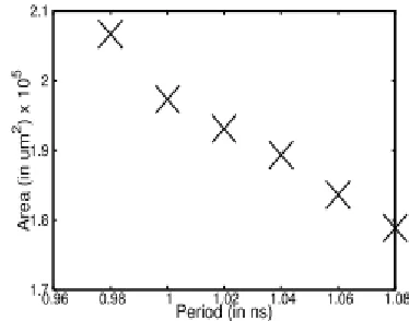
The outlines are blended with best achievable planning imperatives, with requirement of max-area set to zero and worldwide working voltage of 1V. A variety of area as for the day and age limitation, for DPdSP division engineering with 2-organize multiplier, is additionally appeared in Fig 14. The principal point of Fig. 14 relates to the best-timing result, which is displayed in Table III and is utilized for correlation reason. The aggregate dormancy of the designs comprises of pre-FSM cycles, FSM cycles and post-FSM cycles. Likewise, as the proposed designs are iterative in nature, each next info can be connected not long after FSM completes the present preparing. Consequently, the DPdSP division engineering with 1-organize multiplier will have an inertness of 11 cycles and throughput of 10 cycles for DP calculation, a dormancy of 9 cycles and throughput of 8 cycles for double SP calculations. Essentially, on the off chance that with 2-organize multiplier, for DP mode latencyand throughput are 18 cycles and 14 cycles, separately, and for double SP mode, these are 15 cycles and 11 cycles, individually.
Fig. 14: Area-Period Variation of DPdSP Division Architecture with 2-Stage Multiplier @ UMC 90
nm.
The DPdSP division engineering with 1-organize multiplier requires ≈19% more equipment assets and ≈3.6% more period than just DP division design, though with 2-arrange multiplier it needs ≈17.5% a bigger number of assets and ≈5.3% more period than just DP design. The Area/Period overhead is ascertained as (DPdSP - DP)/DP.
A. Functional Verification
B. Related Work and Comparisons
A correlation with earlier craftsmanship on double mode division design is appeared in Table IV. A technological free examination is exhibited regarding Gate-Count for area, FO4-delay for timings, and inertness and throughput as far as clock-cycle checks. Correlation is additionally made in term of a brought together metric, Area × Period (FO4) × T hroughput (in clock − cycle), which ought to be littler for a superior outline.
We have additionally included, in Table IV, the amalgamation consequences of proposed models with "just ordinary" calculation bolster. This is accomplished by evacuating the parts identified with the Step-3 and Step-6 of Algorithm 1. Step-3 compares to the pre-standardization of subnormal operands and it comprises of LOD and Dynamic-Left-Shifter in Fig. 1. While Step-6 compares to post-standardization of any subnormal remainder mantissa and it requires a dynamic right shifter. Along these lines, in this engineering subnormal's are dealt with as zero, both at the info and yield side. These progressions will diminish the inertness of the engineering (with 2-organize multiplier) by two clock cycle, as the first and
third stages stay under single cycle preparing. Be that as it may, in the design with 1-organize multiplier, the idleness will stays same for "just ordinary" support and "with subnormal" computational help. Further, since the throughput of proposed structures depends of the mantissa division FSM preparing, it stays same for design with "just typical" and "with subnormal" handling support.
In addition, for a reasonable correlation, like [18], we have likewise incorporated the combination aftereffects of our proposed designs and [19] utilizing TSMC 250 nm based Standard cell ASIC library usage; with best achievable planning, limitation of max-area set to zero, and worldwide working voltage of 2.5V. In [18], Isseven et. al. has proposed an iterative dualmode DPdSP division engineering utilizing Radix-4 SRT division calculation, a digit-repeat strategy, and integrated utilizing TSMC 250 nm library. Their design has a throughput of 29 clock cycles for twofold precision, and 15 clock cycles for single precision. Their engineering is planned just for ordinary help and cannot process sub-typical calculations and extraordinary cases.
TABLE IV
COMPARISON OF DPdSP DIVISION ARCHITECTURE
In contrast with the right now proposed DPdSP iterative division engineering, Isseven et. al. 's double mode engineering requires significantly bigger area. The throughput of the proposed DPdSP models for twofold precision handling (10 and 15 cycles for 1-phase and 2-organize, separately) is superior to Isseven et. al. 's design throughput (29 cycles). For double
The past single cycle usage of a comparable multiplicative based double mode engineering exhibited in [19] requires an area of 168K identical gates with an estimation of 72 × 106 for Area × Period (FO4) × throughput (in cycles). Because of its single cycle usage, this outline isn't down to earth. Therefore, in contrast with the engineering in [19], the as of now proposed structures are better regarding outline measurements and are handy in nature.
To the best of creator's learning, writing does not contain some other double mode division design, which can bolster DP with two parallel SP divisions. Consequently, because of constrained writing of double mode DPdSP division design, a dialog in view of the techniques utilized as a part of a few (just) twofold precision (DP) execution is given here.
A FPGA based SRT digit-repeat twofold precision division design is proposed by Hemmert et al. [22] with 62 cycles inactivity and 4100 cuts. In this way, as likewise found on account of Isseven et. al. 's DPdSP division work utilizing SRT technique, this strategy needs a bigger inactivity and area. Likewise, execution of digit-repeat technique needs behind multiplicative strategies [2].
Antelo et al. [23] has proposed a mix digit recurrence estimation and Newton-Raphson (NR) emphasis on a FPGA stage, and its execution for twofold precision requires an address space of 15-bit (approx28 18k BRAMs on Xilinx FPGA), and a likeness 29 MULT18x18 IPs. Malik [24] has as of late exhibited the single precision division execution of FPGA gadget utilizing Newton-Raphson and Goldschmidt techniques.
Pasca [9] has proposed a blend of polynomial estimate and NR strategy on an Altera Stratix V gadget, which utilizations around 1000 (ALUTs on Stratix is computationally wealthier that Xilinx LUTs) and a Xilinx likeness 4 BRAMs and 35 multiplier IPs. Wang et al. [25] has announced a 41-bit (10-bit expand 29-bit mantissa) floating point organize division design. It requires a vast area with 62 BRAMs, and answered to have precision misfortune. This strategy requires a tremendous look-into table with address
space of half size of operands, i.e., 227 for DP. Another DP division usage displayed by Fang et al. [26] depends on an underlying estimate with Goldschmidt strategy. This technique for DP division needs a look-into table with address space of 214, and a few multipliers. A current article showed up in [27] talked about a procedure for single mode division, be that as it may, with in a confined extent of standardized operands and furthermore without a real usage. All these talked about designs are in fully unrolled frame. These techniques for twofold precision division, require extensive look-into tables (some are unreasonable), be that as it may, their iterative usage would require just a single multiplier, as if there should arise an occurrence of proposed engineering. Additionally, as these techniques are examined just for single mode (or just) twofold precision design, an intensive examination is required on their practicality and appropriateness for double mode usage. This examination is the part for our future undertaking on this exploration.
Some preparing models likewise depends on the product usage of (single mode) division number juggling using FMA (combined increase include) directions. Like, IA-64 [28] actualizes it, first by processing an underlying estimation of corresponding of divisor and after that figuring the remainder utilizing a grouping of FMA directions. This approach depends on the work [29].
In the comparative degree, thought of current approach may likewise be utilized as a procedure utilizing FMA. Like, in customary FMA division approach, the underlying guess of equal is taken as a seed for other calculation, here, a1−1a2 would go about as a seed for every other calculation to create the remainder, and along these lines, acquires the advantage of FMA. However, this depiction/thought is still half-prepared, it might be a fascinating methodology gave that FMA engineering joins proposed double mode Modified Booth multiplier, and along these lines, it will give a double mode area-productive working. Our future work will concentrate regarding this matter in more points of interest.
The composed Verilog HDL Modules have effectively recreated and confirmed utilizing Isim Simulator and orchestrated utilizing Xilinxise13.2.
SIMULATION RESULTS:
Synthesis results: RTL schematic:
Technology Schematic:
Design summary
Timing Report
VIII. CONCLUSIONS
been tuned to play out the double mode calculation with negligible equipment overhead. The proposed double mode iterative DPdSP engineering have ≈ 17% − 19% area and ≈ 3% − 5% period overhead finished DP just design. The proposed engineering beats the earlier workmanship on this as far as required area, period, throughput in cycles, and brought together metric Area × Period (FO4) × Throughput (in cycles). In view of the current proposed DPdSP division design, comparative models for double mode division can be framed utilizing other multiplicative based techniques (like Newton-Raphson, Goldschmidt) of division. Our future work on this will focus on these structures.
REFERENCES
[1] J.-C. Jeong, W.-C. Park, W. Jeong, T.-D. Han, and M.-K. Lee, “A costeffective pipelined divider with a small lookup table,” IEEE Trans. Comput., vol. 53, no. 4, pp. 489–495, Apr. 2004.
[2] S. F. Oberman and M. Flynn, “Division algorithms and implementations,” IEEE Trans. Comput., vol. 46, no. 8, pp. 833–854, Aug. 1997.
[3] M. K. Jaiswal and R. C. C. Cheung, “High performance reconfigurable architecture for double precision floating point division,” in Proc. 8th Int. Symp. Appl. Reconfigurable Comput. (ARC), Hong Kong, China, Mar. 2012, pp. 302–313.
[4] X. Wang and M. Leeser, “VFloat: A variable precision fixed- and floating-point library for reconfigurable hardware,” ACM Trans. Reconfigurable Technol. Syst., vol. 3, no. 3, pp. 16:1–16:34, Sep. 2010.
[5] M. K. Jaiswal, R. Cheung, M. Balakrishnan, and K. Paul, “Series expansion based efficient architectures for double precision floating point division,” Circuits, Syst., Signal Process., vol. 33, no. 11, pp. 3499–3526,
2014. [Online]. Available:
http://dx.doi.org/10.1007/s00034-014-9811-8
[6] J.-M. Muller et al., Handbook of Floating-Point Arithmetic, 1st ed. Basel, Switzerland: Birkhäuser, 2009.
[7] P. Soderquist and M. Leeser, “Area and performance tradeoffs in floating-point divide and square-root implementations,” ACM Comput. Surv., vol. 28, no. 3, pp. 518–564, Sep. 1996.
[8] B. Parhami, Computer Arithmetic: Algorithms and Hardware Designs, 2nd ed. New York, NY, USA: Oxford Univ. Press, 2010.
[9] B. Pasca, “Correctly rounded floating-point division for DSP-enabled FPGAs,” in Proc. 22nd Int. Conf. Field Program. Logic Appl. (FPL), Aug. 2012, pp. 249–254.
[10] A. Akka¸ s, “Dual-mode quadruple precision floating-point adder,” in Proc. Euromicro Symp. Digit. Syst. Design, 2006, pp. 211–220.
[11] M. Ozbilen and M. Gok, “A multi-precision floating-point adder,” in Proc. Ph.D. Res. Microelectron. Electron. (PRIME), 2008, pp. 117–120.
[12] M. K. Jaiswal, R. C. C. Cheung, M. Balakrishnan, and K. Paul, “Unified architecture for double/two-parallel single precision floating point adder,” IEEE Trans. Circuits Syst. II, Express Briefs, vol. 61, no. 7, pp. 521–525, Jul. 2014.
[13] A. Akka¸ s, “Dual-mode floating-point adder architectures,” J. Syst. Archit., vol. 54, no. 12, pp. 1129–1142, Dec. 2008.
[14] M. Jaiswal, B. Varma, H.-H. So, M. Balakrishnan, K. Paul, and R. Cheung, “Configurable architectures for multi-mode floating point adders,” IEEE Trans. Circuits Syst. I, Reg. Papers, vol. 62, no. 8, pp. 2079– 2090, Aug. 2015.
[15] A. Baluni, F. Merchant, S. K. Nandy, and S. Balakrishnan, “A fully pipelined modular multiple precision floating point multiplier with vector support,” in Proc. Int. Symp. Electron. Syst. Design (ISED), 2011, pp. 45–50.
[17] A. Akka¸ s and M. J. Schulte, “Dual-mode floating-point multiplier architectures with parallel operations,” J. Syst. Archit., vol. 52, no. 10, pp. 549– 562, 2006.
[18] A. Isseven and A. Akka¸ s, “A dual-mode quadruple precision floatingpoint divider,” in Proc. 40th Asilomar Conf. Signals, Syst. Comput. (ACSSC), 2006, pp. 1697–1701.
[19] M. Jaiswal, R. Cheung, M. Balakrishnan, and K. Paul, “Configurable architecture for double/two-parallel single precision floating point division,” in Proc. IEEE Comput. Soc. Annu. Symp. VLSI (ISVLSI), Jul. 2014, pp. 332–337.
[20] IEEE Standard for Floating-Point Arithmetic, IEEE Standard 754-2008, Aug. 2008, pp. 1–70.
[21] L. D. McFearin and D. W. Matula, “Generation and analysis of hard to round cases for binary floating point division,” in Proc. 15th IEEE Symp. Comput. Arithmetic, Jun. 2001, pp. 119–127.
[22] K. S. Hemmert and K. D. Underwood, “Floating-point divider design for FPGAs,” IEEE Trans. Very Large Scale Integr. (VLSI) Syst., vol. 15, no. 1, pp. 115–118, Jan. 2007.
[23] E. Antelo, T. Lang, P. Montuschi, and A. Nannarelli, “Low latency digit-recurrence reciprocal and square-root reciprocal algorithm and architecture,” in Proc. 17th IEEE Symp. Comput. Arithmetic, Jun. 2005, pp. 147–154.
[24] P. Malik, “High throughput floating-point dividers implemented in FPGA,” in Proc. IEEE 18th Int. Symp. Design Diagnostics Electron. Circuits Syst. (DDECS), Apr. 2015, pp. 291–294.
[25] X. Wang and M. Leeser, “VFloat: A variable precision fixed- and floating-point library for reconfigurable hardware,” ACM Trans. Reconfigurable Technol. Syst., vol. 3, no. 3, pp. 16:1–16:34, Sep.
2010. [Online]. Available:
http://doi.acm.org/10.1145/1839480.1839486