A Compact Microstrip Patch Antenna with Reconfigurable Feed
Network for Polarization Diversity
Chunxia Cheng*, Fushun Zhang, and Yali Yao
Abstract—A compact reconfigurable four-feeding microstrip antenna with polarization diversity is presented in this paper. With four triangle-shaped elements as the radiation patch, the proposed antenna can achieve good impedance match for linear polarization (LP), left-hand circular polarization (LHCP) and right-hand circular polarization (RHCP). A four-way power divider made by three Wilkinson power dividers and interconnected with PIN diodes is designed to feed the four elements. By controlling the states of the diodes, the antenna can produce LP, LHCP and RHCP. By using T-shaped slots on the patch and back to back geometry, a compact size of 0.6λ0 ×0.6λ0 ×0.02λ0 is achieved. The
impedance bandwidth of LP is about 80 MHz (3.3%), while the usable bandwidths (overlap of impedance bandwidth and AR bandwidth) of LHCP and RHCP are about 370 MHz (15%) and 250 MHz(10%). The average gain for LP is −2.1 dB, and that for CP is −3.3 dB. This reconfigurable patch antenna with switchable polarization has good performance and simple structure, which can be used for 2.4 GHz wireless communication systems.
1. INTRODUCTION
Recently, reconfigurable antennas have drawn lots of attention due to their ability to improve the performance of the wireless communication systems. For example, the switchable polarization antenna can be used to mitigate signal fading loss caused by multipath effects in wireless local area networks (WLANs) [1]. Moreover, it can be applied to realize frequency reuse to expand the capability in satellite communication systems [2] and used in multiple-input-multiple-output (MIMO) systems [3]. If the antenna can be switched between linear and circular polarization, it will make the antenna more versatile. But, it is difficult to simultaneously realize a good impedance match for circular and linear polarization. The reason is that CP radiation is generated by two degenerate orthogonal linear modes, the input impedance of which is different from that of one resonant mode used to generate LP radiation. Several designs have been proposed to solve this problem [4–6]. In [4], X shaped slot is cut at the center of a rectangular cross-shaped patch and the polarization can be switched by controlling the bias voltage of the two PIN diodes that are inserted into the center of the slot. In [5], two orthogonal notches are cut near opposite angles of the square patch and the polarization can be switched by controlling the bias voltage of the two PIN diodes that are placed on the notches. In [6], the polarization sense can be controlled by the two diodes loaded on two square loop slots in the ground plane. However, both the LP bandwidth and the usable CP bandwidth (overlap of impedance bandwidth and AR bandwidth) of the antennas in the above references are less than 2.5%. In [7], by cutting stair-slots on the ground the impedance bandwidth is increased to 6.1% but the 3-dB AR bandwidth is only 1.5%. A polarization recognizable spiral slot antenna with wide LP and usable CP bandwidth is proposed in [8], but its radiation pattern is bi-directional with a slight angle shifting in its main direction. Another method of designing the reconfigurable antenna is using a switchable feed network [9, 10]. However, the CP
Received 14 July 2014, Accepted 14 August 2014, Scheduled 21 August 2014
* Corresponding author: Chunxia Cheng (cheng [email protected]).
λ0× . λ0 × . λ0
with good impedance bandwidths for both LP and CP modes and 3 dB axial ratio bandwidth for CP mode. Four-feeding structure improves the AR bandwidth and symmetrical performances of the pattern.
2. RECONFIGURABLE ANTENNA
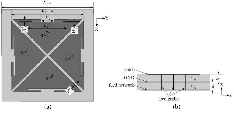
The configuration of the proposed reconfigurable antenna is shown in Fig. 1. As shown in Fig. 1(b), the proposed structure consists of two FR4 substrates (h1 = h2 = 1 mm, εr1 = εr2 = 4.5) with the
same size ofLsub= 70 mm. A four-feeding radiation patch containing four T-shaped slots cut from the four triangle-shaped elements is printed on the top side of the upper layer substrate. The radiation patch has a dimension ofLpatch= 55 mm and the width of the slots between each radiation element is W3 = 1.6 mm. And other parameters areL1 = 10 mm, W1 = 1.5 mm,L2 = 30.2 mm, and W2 = 1 mm.
The ground plane is printed on the bottom side of the upper layer substrate. Four probes pass through the ground plane and soldered to the feeding network underneath the ground plane. In order to prevent the probes from touching the ground plane, four holes are milled on the copper of the ground plane; the holes have a radius of 2 mm and coincide with the probe position. The polarization is controlled by the phase shift between each adjacent element.
(a) (b)
Figure 1. Geometry of the proposed antenna (a) top view and (b) side view.
Figure 2. Feeding network and the associated dc biased network.
1.0 mm×0.6 mm. The dc bias voltage V1 or V2 is either 3 V or −3 V, which can be provided by a dc
source. The current-limited resistorR1 orR2 is 134 Ω. The forward current of the diodeIF is given by
IF = V1(orV2)−2×V R1(orR2)
= 10 mA (1)
In (1),V is the voltage across one diode forIF = 10 mA, which is approximate 0.83 V according to the datasheet [11]. As shown in Table 1, when the dc bias voltage V1 and V2 are 3 V, the diodes D1 ∼D8
are in the ON state and the phase shift of adjacent port (Pout1−Pourt2,Pout2−Pourt3, Pout3−Pourt4)
is 90◦, so left hand circularly polarization (LHCP) is achieved. When the dc bias voltageV1 and V2 are
−3 V, the diodes D9 ∼ D16 are in the ON state and the phase shift of adjacent port (Pout2−Pourt1,
Pout1 −Pourt4, Pout4−Pourt3) is 90◦, so right hand circularly polarization (RHCP) is achieved. When
the dc bias voltage V1 is −3 V and V2 is 3 V, the diodes D5 ∼D12 are in the ON state and the phase
shift of port are Pout1−Pourt2 =Pout3−Pourt4 = 0◦, Pout2−Pourt3 =Pout1−Pourt4 = 180◦, so +45◦
linear polarization is achieved.
Table 1. Bias conditions and polarization states for reconfigurability.
Polarization
states V1 V2
D1,
D2
D3,
D4
D5,
D6
D7,
D8
D9,
D10
D11,
D12
D13,
D14
D15,
D16
LHCP 3 V 3 V ON ON ON ON OFF OFF OFF OFF RHCP −3 V −3 V OFF OFF OFF OFF ON ON ON ON
LP −3 V 3 V OFF OFF ON ON ON ON OFF OFF
3. EXPERIMENTAL RESULTS AND DISCUSSION
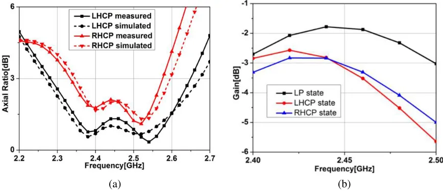
The structure is simulated using the software Ansoft HFSS13. A proposed antenna prototype is fabricated. The top and bottom views are displayed in Figs. 3(a) and (b). In the measurement, a dc block capacitor must be attached to the SMA connector to block the dc current. Fig. 4 shows the reflection coefficients of the proposed antenna operating in the three polarization states. For the LP state, the antenna has a 10 dB return loss bandwidth of 80 MHz from 2.4 GHz to 2.48 GHz (3.3%). When the antenna operates in LHCP or RHCP states, the 10 dB return loss bandwidth is wider than 2.4 GHz WLAN band (2.4–2.48 GHz). As can be seen from the graph, good agreement between the simulation and experiment results is achieved.
Figure 4. Reflection coefficients.
(a) (b)
Figure 5. Comparision of axial ratio and gain: (a) simulated and measured axial ratio; (b) measured gain.
to the wider AR bandwidths feature. The measured antenna gains for the three polarization states from 2.4 GHz to 2.5 GHz are shown in Fig. 5(b). The gains are about −2.7 ∼ −1.8 dB for LP state,
(a) (b)
(c) (d)
(e) (f)
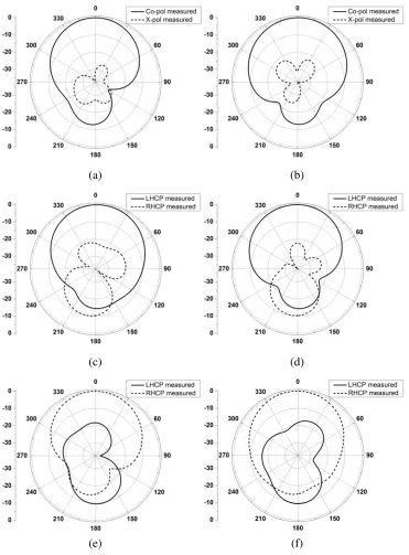
Figure 6. Radiation patterns on (a)ϕ= 45◦ plane and (b)ϕ=−45◦ plane for +45◦ LP; (c)xoz-plane and (d)yoz-plane for LHCP; (e)xoz-plane and (f)yoz-plane for RHCP.
The measured patterns of the reconfigurable patch for +45◦ LP, LHCP and RHCP at 2.44 GHz are shown in Fig. 6. Good radiation and symmetrical performances are obtained for the three polarization states. For the LP, LHCP and RHCP states, the cross polarization in the broadside direction is about
−30 dB,−20 dB and−18 dB, respectively.
RHCP 1.4% 7 dB
This work
LP 3.3% −1.8 dB
0.6λ0×0.6λ0×0.02λ0
LHCP 15% −2.6 dB RHCP 10% −2.8 dB
4. CONCLUSION
A compact reconfigurable four-feeding microstrip antenna with polarization diversity is presented. The proposed structure has four T-shaped slots cut from the four triangle-shaped elements and a feeding network containing three Wilkinson power dividers with sixteen PIN diodes, and the overall volume is only 0.6λ0×0.6λ0×0.02λ0. The radiating patch is fed by four probes passing through the ground
plane and soldered to the feeding network underneath the ground plane. The antenna can produce linear polarization, left-hand circular polarization and right-hand circular polarization by controlling the diodes interconnected in the feed network. A good impedance matching performance for all polarization states is observed without any matching networks. The proposed design achieves a cross-polar level better than−30 dB in linear polarization and over 10% CP bandwidth in both the circular polarization states. Moreover, the prototype of the proposed antenna has symmetrical radiation patterns due to the four-feeding structure. The proposed design is simple and in low cost; therefore it can have some potential applications in the present wireless communications.
REFERENCES
1. Fang, S.-T., “A novel polarization diversity antenna for WLAN applications,”Proc. IEEE Antennas
Propag. Soc. Int. Symp., 282–285, 2000.
2. Yang, X.-X. and S.-S. Zhong, “Analysis of two dual-polarization square-patch antennas,” Microw.
Opt. Technol. Lett., Vol. 26, No. 3, 153–156, 2000.
3. Qin, P. Y., Y. J. Guo, and C. H. Liang, “Effect of antenna polarization diversity on MIMO system capacity,” IEEE Antennas Wireless Propag. Lett., Vol. 9, 1092–1095, 2010.
4. Nishamol, M. S., V. P. Sarin, D. Tony, C. K. Aanandan, P. Mohannan, and K. Vasudevan, “An electronically reconfigurable microstrip antenna with switchable slots for polarization diversity,”
IEEE Trans. Antennas Propag., Vol. 59, No. 9, 3424–3427, 2011.
7. Yang, Z.-X., H.-C. Yang, J.-S. Hong, and Y. Li, “Bandwidth enhancement of a polarization-reconfigurable patch antenna with stair-slots on the ground,” IEEE Antennas Wireless Propag.
Lett., Vol. 13, 579–582, 2014.
8. Chen, Y., F. Zhang, M. Wang, J. Li, and Y. Chen, “A spiral slot antenna with reconfigurable CPW-to-slotline transition for polarization diversity,” Progress In Electromagnetics Research C, Vol. 45, 73–85, 2013.
9. Tsai, J.-F. and J.-S. Row, “Reconfigurable square-ring microstrip antenna,”IEEE Trans. Antennas
Propag., Vol. 61, No. 5, 2857–2860, 2013.
10. Cao, W., B. Zhang, A. Liu, T. Yu, D. Guo, and K. Pan, “A reconfigurable microstrip antenna with radiation pattern selectivity and polarization diversity,” IEEE Antennas Wireless Propag. Lett., Vol. 11, 453–456, 2012.