Multi-Slot Antennas Excited by Novel Dual-Stub Loaded Microstrip
Lines for 4G LTE Bands
Kendrick Q. Henderson1, 2, Saeed I. Latif1, *, Georgios Y. Lazarou1, Satish K. Sharma3, and Azzam Tabbal3
Abstract—A low-profile dual tuning stub loaded microstrip line-fed multi-slot antenna is presented in this paper, which covers most of the significant 4G LTE bands from 850 MHz to 2800 MHz and beyond. The slot antenna consists of three wide slot sections: two orthogonal slots and a circular slot at the junction of those two slots. This multi-slot antenna is excited by a microstrip feed line loaded with dual stubs, which is on the other side of the dielectric substrate. The stubs are terminated across the width of orthogonal slots. Two of these slots along with feed lines are placed on two corners of the ground plane for pattern diversity. Numerical simulation and measurement results on a fabricated prototype demonstrate excellent agreement in scattering parameters. Good port isolation and gains are also obtained. This design is suitable for use in LTE mobile terminals.
1. INTRODUCTION
4G/LTE (Fourth Generation/Long-Term Evolution) standard provides high speed wireless communica-tions for mobile devices and data terminals. The demand for higher data rate has never become so high, and today’s wireless industry has to deal with a tremendous increase in data usage among consumers with a large number of connected smart devices [1]. In current and future state-of-the-art smart mobile terminals, antennas are necessary that are capable of covering multiple 4G/LTE bands ranging from 850 MHz to 2700 MHz. As LTE frequency spectrum is expanding as new spectrum is allocated to LTE, novel antennas are needed to cover this large spectrum while being physically small. Any diversity feature from the antenna is always desired since MIMO (Multiple Input Multiple Output) operation is required by the LTE standard [2, 3].
There has been an enormous effort devoted to the development of new and innovative antennas for smartphones, tablets, laptops, and various other mobile devices. Typically, planar monopoles made of meandered strips, planar inverted-F antennas (PIFA) and slot-based antennas are popularly used in these devices or in base stations [4–17]. A general technique that is applied in many designs is the integration of two or more elements to obtain dual-band operation to cover the lower (around 900 MHz) and upper (around 2 GHz) bands of the large LTE spectrum. In [6], two narrow slotted metallic arms with different lengths, connected together by a shorting metallic strip, are discussed where the longer arm covers the frequency band from 698 MHz to 1510 MHz, and the shorter arm covers the high frequency band (1.52–3.8 GHz) of the LTE Spectrum. Dual strip-based [7–9], double U-shaped patch-based [10] and slot-meandered [11] antennas are designed to cover upper and lower LTE bands.
A pair of folded dipole antennas with three directors in Yagi configuration is presented in [12], which provides 1.7–2.83 GHz of bandwidth. In [13] and [14], PIFA-based arrays are discussed for MIMO,
Received 9 August 2018, Accepted 15 October 2018, Scheduled 18 October 2018
* Corresponding author: Saeed I. Latif ([email protected]).
which cover only several upper bands of LTE from 1800 MHz to 2700 MHz. In [15], a single-element based design with a fractal monopole antenna having a coplanar feed is presented, which provides dual-band operation in both 700- and 2600-MHz LTE dual-bands; however, it is missing important LTE dual-bands between 1800 MHZ and 2400 MHz. The use of open slot elements is reported in [16, 17]. However, in these particular designs, a second element in the form of a metal strip or open loop is used to excite additional resonances or widen the bandwidth.
In this paper, a simple low-profile open wide slot-based antenna for 4G mobile applications is presented that covers a wide range of LTE band frequencies. Multiple slots are arranged at a corner of a ground plane, and are excited by a 50-Ω microstrip feed line. Microstrip line-fed wide slot antennas are inherently wideband structures, since a large number of modes are excited by the feed line which can be combined to obtain large bandwidths [18–22]. A novel feed line loaded with dual stubs is designed which increases the coupling of electromagnetic wave from the feed line to multiple slots effectively and enhances the bandwidth. The proposed antenna operates from 850 MHz to 2800 MHz and beyond, covering almost all the LTE bands including LTE 11 (1500 Lower), LTE 21 (1500 Upper), LTE 24 (1600 L-band), LTE 32 (1500 L-band), and LTE 74–76 (L-band). The antenna designs discussed previously do not cover these bands. However, nowadays it is necessary for any LTE antenna that is used in a mobile terminal to be able to cover these bands for providing universal access.
Two complementary sets of proposed multi-slot are excited at two corners of the ground plane to
provide pattern diversity. This is achieved while maintaining the isolation below −10 dB during the
diversity operation in the entire frequency band of operation. While horizontal and vertical elements are conveniently used in antennas developed for base stations [23–26], it is very challenging to obtain pattern or polarization diversity using a simple low-profile design. This simple slot-based design provides polarization diversity with reasonable isolation and good radiation characteristics.
This paper is organized as follows: Section 2 presents the design of the multi-slot antenna system with a stub-loaded feed network. Section 3 discusses various parameters for design guidelines of the feed. Section 4 presents measured results with comparison to simulated data. Ansys HFSS, version
16, is used for all simulations. In this paper, the bandwidth definition of S11 = −6 dB (VSWR
= 3) is used as the design specification of handheld mobile user equipment antennas, which is widely accepted [7, 11, 16, 17, 27, 28].
2. MICROSTRIP LINE-FED MULTI-SLOT ANTENNA GEOMETRY
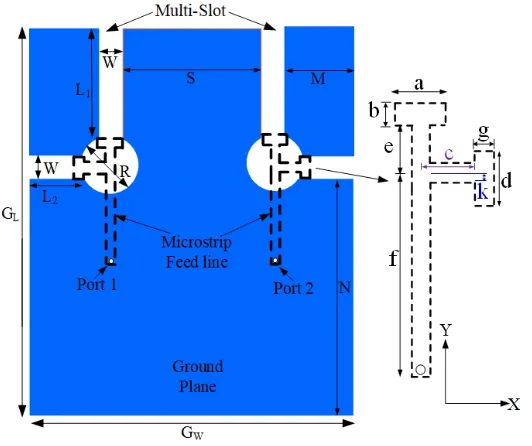
Figure 1 shows the geometry of the multi-slot antenna. It consists of two wide straight slots cut into
a ground plane, where the relatively longer slot (L1) is alongy-axis, and the shorter slot (L2) is along
x-axis. These orthogonal slots are kept open at their one end, while the other end is terminated in a
circular slot of diameter ‘R’. These slots are excited by a microstrip feed line on the other side of the
grounded dielectric substrate. TMM4 material with permittivity of 4.5 and height of 3.175 mm from Rogers Corporation is used as the substrate.
A novel feed network with tuning stubs is designed to excite all three slots effectively. The main line
feedline (f) is terminated in two T-shaped stubs at the circular slot center. The feed line is connected
to a 50-Ω SMA connector. The detail of the feed line is depicted in Fig. 1 indicating all parameters.
The T-shaped stub overL1 slot has two segments: a top segment with widthaand depthb. The other
segmente extends from the feed line (or from the center of the circular slot) to the junction ofL1 slot
and circular slot. This segment has the same width as the feed line width, which is chosen to be 4.5 mm
so that its characteristic impedance is 50-Ω. Similarly, the T-shaped stub overL2 slot has two segments:
the top segment along y-axis with dimensions: d×g, and thec segment having the same width as the
feed line width.
The multi-slot configuration, when excited by this novel stub-loaded feed line, provides wide impedance bandwidth, with each slot covering a specific frequency spectrum of LTE bands. Thus, initial slot lengths are chosen with an aim to obtain frequency operation from 850 MHz to 2700 MHz. For a set of initial dual stub-loaded feed line parameters, slot dimensions are chosen so that the lowest order or the dominant mode of each of these slots is excited, which are close enough to obtain a wide
frequency of operation. While L1 and L2 slots are responsible for low and high frequency bands, the
Figure 1. Geometry of the multi-slot antenna and the feed network with dual stub-loaded feed line.
In this study, the following slot dimensions are used, which are chosen based on slot dimensions that
provide resonance covering lower and upper LTE bands: L1= 54.7 mm,L2 = 16.7 mm, andR= 12 mm.
The location of slots with respect to ground plane edges are indicated withL2, M and N. L1 slots on
two sides of the ground plane are separated by a distance, S. In simulations, a ground plane size of
140 mm (=GL)×80 mm (= GW) is used. For tablet or notebook applications, a larger ground plane
can be considered.
3. STUDY OF FEED PARAMETERS
A parametric study is conducted to optimize the antenna bandwidth, as well as to effectively design the feed network. The following analysis is conducted for stub-tuning and optimizing antenna parameters.
3.1. Stub Tuning for Widening the Bandwidth
Initially, the top segment of the T-shaped stubs on bothL1 and L2 slots is located symmetrically with
respect to the other segment. An extensive study is conducted on the feed line termination over slots, stub lengths, widths, the location of the top segment of the T-shaped stub with respect to the other, etc. Only two parameters are discussed here for brevity, which, in fact, provide an easy tuning of the
impedance: the asymmetric location of the top segment of the T-shaped stub overL2slot, and its width,
d. The width of the top segment of the T-shaped stub over L1 slot, a, is kept the same as d. However,
two different depths,b andg, are used for the top segment of the T-shaped stubs over L1 andL2 slots,
respectively. The location of the top segment of the T-shaped slot overL2 slot is made asymmetric by
introducing an offset with respect to the other segment. This offset is denoted as ‘k’ in Fig. 1. k= 0
indicates the symmetric case, whereas, when the top segment of the T-shaped stub is moved down (−y
axis) with respect to the other segment, the value ofkincreases. The effect of the variation of ‘k’ on the
reflection coefficient is shown in Fig. 2. A larger offset of the top segment provides a better impedance
matching at higher frequencies, since this stub is over the shorter slot, L2. On the other hand, if the
-30 -24 -18 -12 -6 0
0.5 1 1.5 2 2.5 3
R eflec ti o n C o effi ci en t, S11 (d B ) Frequency (GHz) k=0mm k=0.5mm k=1mm
Figure 2. Effects of varying the offset amount,
k, on the T-shaped stub overL2 slot onS11of the
antenna. The slot dimensions and other antenna parameters are mentioned in Table 1.
-36 -30 -24 -18 -12 -6 0
0.5 1 1.5 2 2.5 3
R eflec ti o n C o effi ci en t, S11 (d B ) Frequency (GHz) a=d=8mm a=d=10mm a=d=11mm
Figure 3. Effects of varying stub widths, a
and d, over L1 and L2 slots, respectively. The
slot dimensions and other antenna parameters are mentioned in Table 1.
3.2. Optimized Antenna Parameters
Based on parametric studies, the slot dimensions and feed stubs are judicially selected to obtain a wide impedance bandwidth covering most of the LTE bands. Offset of the top segment of the T-shaped stub
over L2 slot is chosen to bek= 1 mm. Other optimized antenna parameters are listed in Table 1. As a
complimentary multi-slot antenna excited by a dual stub-loaded feed line is added on the other corner of the ground plane, the isolation between two ports is also obtained from the simulation tool.
Using the optimized parameters, two dual multi-slot antenna prototypes with two ports were
fabricated on grounded TMM4 dielectric substrates having the size: GL= 140 mm and GW = 80 mm.
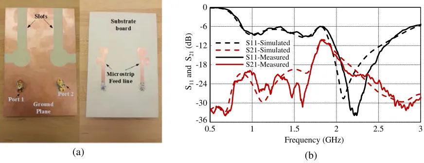
Fig. 4(a) shows the fabricated antenna with SMA connectors. The scattering parameters of the antenna were tested on an Anritsu 37369A Vector Network Analyzer in the Applied Electromagnetics Research
Laboratory at the University of South Alabama. Simulated and measured S11 and S21 are shown
in Fig. 4(b). The measured results are in excellent agreement with the simulated ones. Simulated
S11=−6 dB bandwidth of this optimized antenna is: 110% (860 MHz to 2,962 MHz), and the measured
bandwidth is: 109.5% (850 MHz to 2,906 MHz) with isolation −10 dB for this bandwidth without any
additional decoupling elements. Isolation is better than −18 dB from 850 MHz to 1700 MHz and from
2 GHz and higher.
(a) (b) -36 -30 -24 -18 -12 -6 0
0.5 1 1.5 2 2.5 3
S11 and S21 (d B ) Frequency (GHz) S11-Simulated S21-Simulated S11-Measured S21-Measured
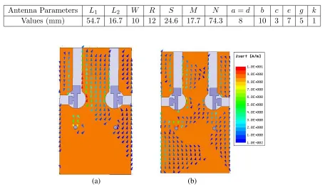
Current distributions at two ends of the frequency of operation, 1 GHz and 2.5 GHz, are presented in Figs. 5(a) and 5(b), respectively. It is evident that the strongest current is along the slot edges when that slot is excited, which is responsible for the radiation from this antenna.
Table 1. Optimized antenna parameters for the multi-slot antenna with the novel feed network.
Antenna Parameters L1 L2 W R S M N a=d b c e g k
Values (mm) 54.7 16.7 10 12 24.6 17.7 74.3 8 10 3 7 5 1
(a) (b)
Figure 5. Current distribution on the ground plane of the microstrip slot antenna at (a) 1 GHz and (b) 2.5 GHz, with port 1 is excited and port 2 is terminated in a 50-Ω load.
In order to demonstrate significance of the T-shaped stubs on the feed line for impedance matching, the case without these stubs is simulated. With reference to Fig. 1, this case indicates the scenario with
the feed line withoutaand esegments overL1 slot, andc anddsegments over theL2 slot. The effects
of removing stubs on the feed line on S-parameters are presented in Fig. 6. Without stubs, the S11
value degrades between 1.5 GHz and 2 GHz, as well as in the lower end of the frequency band. The isolation between two ports also degrades.
4. RADIATION PATTERN ANALYSIS
Two complementary slots are used in the design to obtain pattern diversity when used in LTE mobile
terminals, which can be understood by observing its radiation patterns inφ= 45◦ andφ= 135◦ planes.
The multi-slot antenna consists of two orthogonal straight slots and a circular slot, and as such, the
antenna patterns will be dominant either in the φ = 45◦ plane or φ = 135◦ plane for the right and
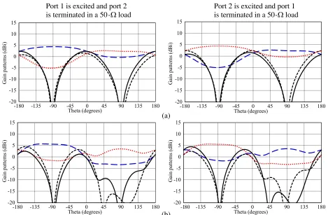
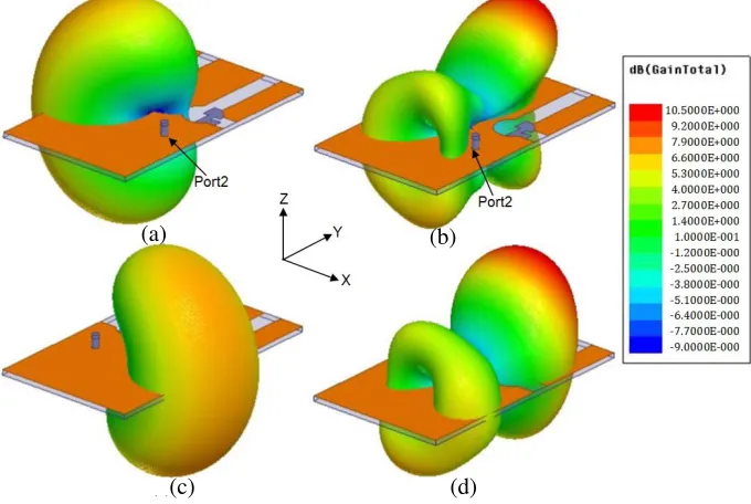
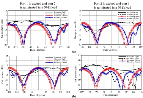
left slots, respectively. Fig. 7 shows simulated radiation patterns at 4 different frequencies within the band in these two planes. The figures on the left are with the left multi-slot excited, while the feed of the right multi-slot matched to a 50-Ω load. The plots on the right show radiation patterns with port 2 excited and port 1 terminated in a 50-Ω load. The patterns in Fig. 7(a) indicate that the main
component,Eφ, has a complementary coverage in theφ= 45◦ by exciting two ports alternately. In the
φ= 135◦ plane, the pattern shape and coverage zone ofEφreverse. The antenna has a gain of 2.3 dBi
or over from θ =−180◦ to 180◦ when one port is excited and the other terminated in a 50-Ω load in
both principal planes. Thus, two slots provide peak radiation mainly in two directions: when the left
excited, toward θ = 90◦ direction. This is also evident in the 3-D radiation pattern plots in Fig. 8(a) for the same frequency. This feature can be exploited to achieve pattern diversity from this multi-slot configuration.
As the frequency increases, the antenna becomes more directive with peak gain of 5.6 dBi at 1.5 GHz.
The pattern shape and coverage zone ofEφreverse as the excitation of port changes, as can be noticed in
Fig. 7(b). At higher frequencies, the antenna demonstrates more directive radiation patterns with peak gain values close to 10 dBi. At 2.5 GHz, multiple beams can be noticed in the 2-D and 3-D radiation patterns in Figs. 7(d) and 8(b), respectively. However, the antenna exhibits its pattern diversity feature at all frequencies.
An effective way to measure the diversity performance of an antenna is to estimate the correlation
coefficient (ρ) based on scattering parameters and the radiation efficiency of the antenna [29]. A low
-36 -30 -24 -18 -12 -6 0
0.5 1 1.5 2 2.5 3
S11 and S21 (d B ) Frequency (GHz)
S11 (With stub) S21(With Stub) S11 (No stub) S21(No Stub)
Figure 6. Simulated scattering parameters of the proposed antenna in Figure 1 with and without T-shaped tuning stubs on the feed network.
Port 1 is excited and port 2 is terminated in a 50-Ω load
Port 2 is excited and port 1 is terminated in a 50-Ω load
(a) (b) -20 -15 -10 -5 0 5 10 15
-180 -135 -90 -45 0 45 90 135 180
G ain patte rn s (d Bi) Theta (degrees) -20 -15 -10 -5 0 5 10 15
-180 -135 -90 -45 0 45 90 135 180
G ain patte rn s (d Bi) Theta (degrees) -20 -15 -10 -5 0 5 10 15
-180 -135 -90 -45 0 45 90 135 180
G ain patte rn s (d Bi) Theta (degrees) -20 -15 -10 -5 0 5 10 15
-180 -135 -90 -45 0 45 90 135 180
(c)
(d) -20
-15 -10 -5 0 5 10 15
-180 -135 -90 -45 0 45 90 135 180
G
ain patte
rn
s
(d
Bi)
Theta (degrees)
-20 -15 -10 -5 0 5 10 15
-180 -135 -90 -45 0 45 90 135 180
G
ain patte
rn
s
(d
Bi)
Theta (degrees)
-20 -15 -10 -5 0 5 10 15
-180 -135 -90 -45 0 45 90 135 180
G
ain patte
rn
s
(d
Bi)
Theta (degrees)
-20 -15 -10 -5 0 5 10 15
-180 -135 -90 -45 0 45 90 135 180
G
ain patte
rn
s
(d
Bi)
Theta (degrees)
Figure 7. Simulated gain patterns of the antenna in two principal planes at (a) 1 GHz, (b) 1.5 GHz, (c) 2 GHz and (d) 2.5 GHz.
(a) (b)
(c) (d)
0 0.06 0.12 0.18 0.24 0.3
0.8 1 1.2 1.4 1.6 1.8 2 2.2 2.4 2.6 2.8
C o rrelat io n C o effi ci en t, ρ Frequency (GHz)
Figure 9. Simulated correlation coefficient (ρ) with frequency fromS-parameters.
(a) (b) -20 -15 -10 -5 0 5 10 15
-180 -135 -90 -45 0 45 90 135 180
G ain patte rn s (d Bi) Theta (degrees) Simulated E-phi Measured E-phi Simulated E-theta Measured E-theta -20 -15 -10 -5 0 5 10 15
-180 -135 -90 -45 0 45 90 135 180
G ain patte rn s (d Bi) Theta (degrees) Simulated E-phi Measured E-phi Simulated E-theta Measured E-theta -20 -15 -10 -5 0 5 10 15
-180 -135 -90 -45 0 45 90 135 180
G ain patte rn s (d Bi) Theta (degrees) Simulated E-phi Measured E-phi Simulated E-theta Measured E-theta -20 -15 -10 -5 0 5 10 15
-180 -135 -90 -45 0 45 90 135 180
G ain patte rn s (d Bi) Theta (degrees) Simulated E-phi Measured E-phi Simulated E-theta Measured E-theta
Port 1 is excited and port 2 is terminated in a 50-Ω load
Port 2 is excited and port 1 is terminated in a 50-Ω load
Figure 10. Simulated and measured gain patterns at 1 GHz for the antenna in the (a) φ= 45◦ plane,
and (b) (a) φ= 135◦ plane.
value of the correlation coefficient (less than 0.3) is desired for acceptable diversity performance in 4G [30]. The simulated correlation coefficient is plotted in Fig. 9, and results show that it is below
0.025 across the operating band, accept around 1.82 GHz whereS21 value is relatively higher. However,
at this frequency, it is still well below 0.3. This study demonstrates that signals from two ports are decorrelated and good diversity performance can be achieved from this antenna.
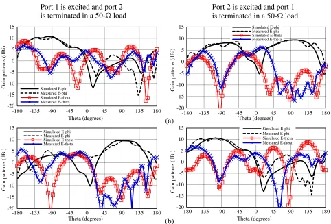
San Diego State University to verify simulated gain data. Patterns only in the lower (1 GHz) and upper (2.5 GHz) LTE bands are presented here for brevity in Figs. 10 and 11, respectively. Simulated and
measured radiation patterns at 1 GHz in the ϕ = 45◦ plane are compared in Fig. 10, where both
ports are alternately excited terminating the other in a 50-Ω load. The antenna demonstrates nearly omnidirectional radiation pattern by alternatingly excited port 1 and port 2. At the upper end frequency of 2.5 GHz, the antenna shows more directive patterns, as can be noticed in Fig. 11. Like simulated patterns, multiple beams are evident in the case of the excitation of port 2. At both frequencies, the co-polarization pattern shape and coverage zone reverse with the change of excitation ports. The simulated patterns are in good agreement with the measured ones in both planes. Some discrepancies noticed in the simulated and measured patterns can be attributed to comparable feed line dimensions in terms of wavelength causing some scattering of signals. Similar radiation patterns were observed in the middle LTE bands as well.
The antenna radiation efficiency is calculated for the operating frequency using Ansys HFSS and presented as a function of frequency in Fig. 12. The antenna exhibits radiation efficiency over 80% from 895 MHz to 1750 MHz. At higher frequency, the antenna exhibits higher gain as the antenna size appears to be bigger, and the radiation efficiency over 90% from 1975 MHz to 2800 MHz is achieved. A radiation efficiency of 66% can be noticed around 1845 MHz, where the port isolation is relatively poor for this antenna. Overall, the antenna demonstrates a good radiation efficiency over the frequency of operation.
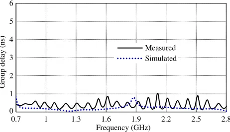
Finally, the antenna was experimentally verified for the group delay using the two identical fabricated antennas. The transmit and receive antennas were facing each other while connected to two ports of the Anritsu Vector Network Analyzer. The antennas were placed in the far-field at the
Port 1 is excited and port 2 is terminated in a 50-Ω load
Port 2 is excited and port 1 is terminated in a 50-Ω load
(a) (b) -20 -15 -10 -5 0 5 10 15
-180 -135 -90 -45 0 45 90 135 180
G ain patte rn s (d Bi) Theta (degrees) Simulated E-phi Measured E-phi Simulated E-theta Measured E-theta -20 -15 -10 -5 0 5 10 15
-180 -135 -90 -45 0 45 90 135 180
G ain patte rn s (d Bi) Theta (degrees) Simulated E-phi Measured E-phi Simulated E-theta Measured E-theta -20 -15 -10 -5 0 5 10 15
-180 -135 -90 -45 0 45 90 135 180
G ain patte rn s (d Bi) Theta (degrees) Simulated E-phi Measured E-phi Simulated E-theta Measured E-theta -20 -15 -10 -5 0 5 10 15
-180 -135 -90 -45 0 45 90 135 180
G ain patte rn s (d Bi) Theta (degrees) Simulated E-phi Measured E-phi Simulated E-theta Measured E-theta
Figure 11. Simulated and measured gain patterns at 1 GHz for the antenna in the (a) φ= 45◦ plane,
0 20 40 60 80 100
0.7 1 1.3 1.6 1.9 2.2 2.5 2.8
Radiatio
n
effi
ci
en
cy
(
%
)
Frequency (GHz)
Figure 12. Simulated radiation efficiency of the proposed antenna as a function of frequency.
0 1 2 3 4 5 6
0.7 1 1.3 1.6 1.9 2.2 2.5 2.8
G
ro
u
p de
la
y
(
n
s)
Frequency (GHz) Measured Simulated
Figure 13. Simulated and measured group
delay of the antenna. Two identical antennas
were separated by a distance of 50 cm for this measurement with port 1 of both antennas excited while port 2 terminated in a 50-Ω load.
lowest operating frequency at a distance 50 cm. The measured group delay is shown in Fig. 13, where it is compared with the simulated one. The variation in measured and simulated group delays is less than 0.7 ns. The average simulated group delay is approximately 0.2 ns and the measured one is about 0.5 ns. The ripples in the measured group delay can be attributed to scattering caused by VNA cables. This measurement was conducted with port 1 of both antennas excited while port 2 terminated in a 50-Ω load. The other measurement with port 2 of both antennas excited while port 1 terminated in a 50-Ω load gave very similar results and, therefore, is not repeated here. This study confirms that the antenna shows fairly constant group delay or phase linearity in the operational bandwidth.
5. CONCLUSIONS
The simulated and measured results of a multi-slot antenna excited by a novel stub-loaded microstrip feed line have been presented in this paper. The multi-slot is composed of two orthogonal slots and a circular slot in between. Several design parameters are studied to optimize the antenna bandwidth. The antenna covers most of LTE frequency bands from 850 MHz to 2700 MHz, including 1500 MHz and 1600 MHz bands. Two complimentary slots placed on two corners of a ground plane provides pattern diversity suitable for LTE wireless applications. The simulation results have been verified by measurements from fabricated prototypes. With large bandwidth and beam coverage, this slot-based simple antenna design will most certainly find applications in globally compatible LTE wireless devices.
REFERENCES
1. Cisco Visual Networking Index: Forecast and Methodology, 2016–2021, Feb. 11, 2018,
[Online]. Available: https://www.cisco.com/c/en/us/solutions/collateral/service-provider/visual-networking-index-vni/complete-white-paper-c11-481360.pdf.
2. Schwarz, S., J. C. Ikuno, M. ˇSimko, M. Taranetz, Q. Wang, and M. Rupp, “Pushing the limits of
LTE: A survey on research enhancing the standard,” IEEE Access, Vol. 1, 51–62, 2013.
3. Dahlman, E., S. Parkvall, and J. Skold, 4G: LTE/LTE-Advanced for Mobile Broadband, 2nd
Edition, Elsevier Ltd., 2014.
4. Del Barrio, S. C. and G. F. Pedersen, “Antenna design exploiting duplex isolation for 4G application
on handsets,” Electron. Lett., Vol. 49, 1197–1198, 2013.
5. Del Barrio, S. C., T. Holmgaard, M. Christensen, A. Morris, and G. F. Pedersen, “Screen-printed
silver-ink antennas for frequency-reconfigurable architectures in LTE phones,” Electron. Lett.,
6. Sanad, M. and N. Hassan, “Novel wideband MIMO antennas that can cover the whole LTE
spectrum in handsets and portable computers,” The Scientific World Journal, Vol. 2014, Article
ID 694805, 9 pages, 2014.
7. Chu, F. H. and K. L. Wong, “Planar printed strip monopole with a closely-coupled parasitic
shorted strip for eight-band LTE/GSM/UMTS mobile phone,” IEEE Trans. Antennas Propag.,
Vol. 58, 3426–3431, 2010.
8. Zhang, T., R. Li, G. Jin, G. Wei, and M. M. Tentzeris, “A novel multiband planar antenna for
GSM/UMTS/LTE/Zigbee/RFID mobile devices,” IEEE Trans. Antennas Propag., Vol. 59, 4209–
4214, 2011.
9. Chen, Z., Y.-L. Ban, J.-H. Chen, J. L.-W. Li, and Y.-J. Wu, “Bandwidth enhancement
of LTE/WWAN printed mobile phone antenna using slotted ground structure,” Progress In
Electromagnetics Research, Vol. 129, 469–483, 2012.
10. Zhang, X. Y., Y. Zhang, Y. M. Pan, and W. Duan, “Low-profile dual-band filtering patch antenna
and its application to LTE MIMO system,”IEEE Trans. Antennas Propag., Vol. 65, 103–113, 2017.
11. Elamin, N. I. M., T. A. Rahman, and A. Y. Abdulrahman, “New adjustable slot meander patch
antenna for 4G handheld devices,” IEEE Antennas Wireless Propag. Lett., Vol. 12, 1077–1080,
2013.
12. Wang, Z., X. Liu, Y. Yin, and J. Wu, “Dual-element folded dipole design for broadband multilayered
Yagi antenna for 2G/3G/LTE applications,” Electron. Lett., Vol. 50, 242–244, Feb. 2014.
13. Yang, L. and T. Li, “Box-folded four-element MIMO antenna system for LTE handsets,”Electron.
Lett., Vol. 51, No. 6, 440–441, 2015.
14. Qin, Z., W. Geyi, M. Zhang, and J. Wang, “Printed eight-element MIMO system for compact and
thin 5G mobile handset,”Electron. Lett., Vol. 52, 416–418, 2016.
15. Lizzi, L. and A. Massa, “Dual-band printed fractal monopole antenna for LTE applications,”IEEE
Antennas Wireless Propag. Lett., Vol. 10, 760–763, 2011.
16. Wong, K. L. and C. Y. Huang, “Triple-wideband open-slot antenna for the LTE metal-framed
tablet device,”IEEE Trans. Antennas Propag., Vol. 63, 5966–5971, 2015.
17. Wong, K. L. and Y. C. Chen, “Small-size hybrid loop/open-slot antenna for the LTE Smartphone,”
IEEE Trans. Antennas Propag., Vol. 63, 5837–5841, 2015.
18. Rajgopal, S. K. and S. K. Sharma, “Investigations on ultrawideband pentagon shape microstrip slot
antenna for wireless communications,” IEEE Trans. Antennas Propag., Vol. 57, No. 5, 1353–1359,
2009.
19. Kahrizi, M., T. K. Sarkar, and Z. A. Maricevic, “Analysis of a wide radiating slot in the ground
plane of a microstrip line,” IEEE Trans. Microwave Theory Techniques, Vol. 41, 29–37, 1993.
20. Sze, J.-Y. and K.-L Wong, “Bandwidth enhancement of a microstrip-line-fed printed wide-slot
antenna,” IEEE Trans. Antennas Propag., Vol. 49, 1020–1024, 2001.
21. Sharma, S. K., L. Shafai, and N. Jacob, “Investigations of wide band microstrip slot antenna,”
IEEE Trans. Antennas Propag., Vol. 52, 865–872, 2004.
22. Latif, S. I., L. Shafai, and S. K. Sharma, “Bandwidth enhancement and size reduction of microstrip
slot antennas,”IEEE Trans. Antennas Propag., Vol. 53, 994–1003, 2005.
23. Huang, H., Y. Liu, and S. Gong, “Broadband dual-polarized omnidirectional antenna for
2G/3G/LTE/WiFi applications,” IEEE Antennas Wireless Propag. Lett., Vol. 15, 576–579, 2016.
24. Dai, X. W., Z. Y. Wang, C. H. Liang, X. Chen, and L. T. Wang, “Multiband and dual-polarized
omnidirectional antenna for 2G/3G/LTE Application,” IEEE Antennas Wireless Propag. Lett.,
Vol. 12, 1492–1495, 2013.
25. Dong, Y., J. Choi, and T. Itoh, “Vivaldi antenna with pattern diversity for 0.7 to 2.7 GHz cellular
band applications,” IEEE Antennas Wireless Propag. Lett., Vol. 17, 247–250, 2018.
26. Michel, A., P. Nepa, M. Gallo, I. Moro, A. P. Filisan, and D. Zamberlan, “Printed wideband
antenna for LTE-Band automotive applications,” IEEE Antennas Wireless Propag. Lett., Vol. 16,
27. Byeongkwan, K., et al., “Isolation enhancement of USB dongle MIMO antenna in LTE 700 band
applications,” IEEE Antennas Wireless Propag. Lett., Vol. 11, 961–964, 2012.
28. Ban, Y.-L., J.-H. Chen, S.-C. Sun, L. W. Li, and J.-H. Guo, “Printed monopole antenna with a
long parasitic strip for wireless USB dongle LTE/GSM/UMTS operation,”IEEE Antennas Wireless
Propag. Lett., Vol. 11, 767–770, 2012.
29. Blanch, S., J. Romeu, and I. Corbella, “Exact representation of antenna system diversity
performance from input parameter description,” Electron. Lett., Vol. 39, 705–707, 2003.