LUT Optimization for scattered Arithmetic-Based Block
Least Mean Square Adaptive (LMSA) Filter
K. Siva Naga Leela & S. V. Ravi Kumar
1 PG Scholar, Dept of ECE, Rise Krishna Sai Gandhi Group of Institutions, Ongole, AP, India.
2Associate Professor, Dept of ECE, Rise Krishna Sai Gandhi Group of Institutions, Ongole, AP, India.
Abstract:
In this manuscript, an adaptive FIR filter
for high throughput, area and power
efficient design will be introducing using
distributed arithmetic (DA). DA is a bit
serial computational action and uses
equivalent concurrent realization of
filtering weight update proposal for
improving the throughput rate. As well as
for high throughput rate and low area
consumption the DA uses set of smaller
dynamic parallel look up tables (LUTs).
To reduced area requirement, sampling
period and critical path, the conditional
carry save accumulation of shift
accumulator using full adder string
circuitry will used in placed of
conventional adder based shift
accumulation. The Least mean square
(LMS) algorithm is introduced to update
weight and decline the mean square root
error between desired and expected
output. For the attenuation in power
consumption of proposed design, the
system has the two separate clocks; slower
for all computations except carry save
accumulation. The carry save
accumulation required separate fastest
clock. The designed Adaptive FIR Filter
system will include relatively less number
of look up tables, employed half adders in
replace of some full adders to reduce
required area of filter and less number of
multiplexer and thus required power
consumption will be less.
Keyword: Adaptive filter, Distributed
arithmetic (DA), least mean square
(LMS) algorithm, LUTs, Inner Product
unit.
I. INTRODUCTION
Adaptive FIR filter is a system with a
linear filter that has a transfer function
managed by variable parameters and a
means to adjust those parameters
according to a suitable algorithm. Most
adaptive FIR filters are digital filters only
because of the difficulty faced of the
Adaptive filters are widely used in several
digital signal processing applications. The
most usually used adaptive filter is the
tapped-delay line finite impulse response
(FIR) filter whose weights are updated by
the famous Widrow–Hoff least mean
square (LMS) algorithm. Because it has
not only simple in nature but also it has
satisfactory convergence performance [1].
The direct form configuration on the
forward path of the FIR filter results in a
long critical path due to an inner-product
computation to obtain a filter output.
Therefore, it is necessary to minimize the
critical path of the structure so that the
critical path could not beat the sampling
period, when the input signal sampling rate
has a high. In current years, without
multiplier DA-based system [2] has gained
for thesignificant popularity for its
high-throughput processing potential and
reliability, which result in cost-effective
and area–time efficient computing
structures. Hardwarecapable DA-based
design of adaptive filter has been
suggested by Allred et al using two
separate lookup tables (LUTs) for filtering
and weight update. Author[3], have
enhanced there system for filtering as well
as weight updating by using only one
lookup table. However, the system do not
support high sampling rate for each new
sample since they occupy several cycles
for LUT updates. In a recent manuscript
anticipated a resourceful design DA-based
adaptive filter with very low alteration
delay and with high-speed [4].
This designed based on DA and LMS
algorithm for lesser area, power as well as
very high-throughput pipelined realization
of adaptive FIR filter with minimum
adaptation time delay
The designed system advantages are as
follows
1) By using a parallel LUT update the
throughput rate is extensively
improved.
2) Also throughput is significantly
increased by concurrent
implementation of filtering and
weight updating.
3) In this, uses a conditional
carry-save accumulation of signed partial
inner products to reduce the
sampling period instead of
Conventional adder-based shift
accumulation.
The designed signed carry-save
accumulation also helps to minimum the
II. DESIGN METHODOLOGY
LMS Algorithm
The LMS update algorithm is particularly
simple if the variable filter has FIR tapped
delay line in nature. Normally, after each
sample, the FIR filter coefficients are
adjusted as below:
for μ is called the convergence factor
The LMS algorithm does not need that x
values have any particular bond; therefore
it can be used to adjust an FIR filter and a
linear combiner. So the equation is given
by:
The effect of the LMS algorithm is at each
time, k, to create a small change in each
weight. The direction of the change is such
that it would reduce the error value if it
had been used at time k. The change in
each weight magnitude depends on the
associated x value, convergence factor μ
and the error at time k. The output changed
the most, as any change in values of
weight magnitude. There should be no
change in the weights, only at the time of
error free system. The changing the weight
makes no difference, if the associated
value of x is zero [2].
LMS ADAPTIVE FILTER
The Least Mean Square (LMS) algorithm
was introduced by Widrow and Hoff in
1959. The LMS algorithm has established
itself as the mainstay of adaptive signal
processing for two major reasons:
Simplicity of implementation and a
computational efficiency that is linear in
the number of adjustable parameters.
Robust performance
It is an adaptive algorithm, which makes
use of a gradientbased method of steepest
decent. LMS algorithm uses the estimates
of the gradient vector from the data that
becomes available. LMS incorporates an
iterative procedure that makes successive
corrections to the weight vector in the
negative direction of the gradient vector
which eventually leads to the minimum
mean square error (MSE). The gradient is
the del operator (partial derivative) and is
applied to find the divergence of a
function, which represents the error
withrespect to the nth coefficient in this
case. The LMS algorithm approaches
to minimize error by taking the negative
gradient of the function.
Fig.1: LMS Implementation Using FIR
Filter
The desired signal d(n) is tracked by
adjusting the filter coefficients c(n). The
input reference signal x(n) is a known
signal that serves as an input to the FIR
filter. The difference between d(n) and
y(n) is the error e(n). The error e(n) is then
given to the LMS algorithm to compute
the filter coefficients c(n+1) which
minimizes the error in an iterative manner.
The LMS equation for computing the FIR
coefficients is as follows:
The convergence time of the LMS
algorithm depends on the step size µ.
The input vector x(n) and the weight
vector c(n) at the nth training iteration are
respectively given by:
In pipelined architecture, the feedback
error e(n) becomes available only after a
definite number of cycles, called the
adaptation delay. So, the pipelined
architectures make use of delayed error e(n
− m) in order to update the current weight instead of the most recent error, where ‘m’
is the adaptation delay. The weight-update
equation of such delayed LMS adaptive
filter is given by:
III. DISTRIBUTED
ARITHMETIC BASED
APPROACH
The LMS adaptive filter involves
performing of an innerproduct
computation during each cycle, which
contributes to the most of the critical path.
Let the inner product of eqn. (3) be given
whereck and xk for 0 ≤ k ≤ N − 1 are the
N-point vectors corresponding to the
current weights and most recent N − 1
input, respectively. If L is assumed to be
the bit width of the weight, then each
component of the weight vector may be
expressed in two’s complement
representation as follows:
whereckl denotes the lth bit of ck
Substituting (8), we can write (7) in an
expanded form as follows:
Now for converting the sum-of-products
form of (7) into a distributed form, the
order of summations over the indices k and
l in (6) may be switched to get:
and the inner product given by (10) can be
computed as:
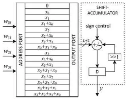
Fig.2: Traditional implementation of
DA-based four-point inner product
Fig.3: Carry-save implementation of shift
accumulation
Hence, the inner product of eqn. (11) can
be calculated in L cycles of shift
accumulation, which is then followed by
LUTread operations corresponding to L
number of bit slices {ckl} for 0 ≤ l ≤ L − 1,
as shown in Fig. 2. As the shift
accumulation in Fig. 2 encompasses
substantial critical path, it is performed
using carry-save accumulator, as shown in
one after the other in the LSB to the MSB
order to the carry-save accumulator.
However, the negative (two’s
complement) of the LUT output is required
to be accumulated in case of MSB slices.
So, the entire bits of LUT output are
passed through XOR gates with a
sign-control input which is set to ‘1’ only when
the MSB slice appears as address. The
XOR gates thus produce the one’s
complement of the LUT output
corresponding to the MSB slice but do not
affect the output for other bit slices.
Finally, the sum and carry words that are
acquired after L clock cycles are essential
to be added by a final adder which has
been excluded from the figure, and the
input carry of the final adder is needed to
be set to ‘1’ to account for the two’s
complement operation of the LUT output
corresponding to the MSB slice. The
content of the kth LUT location can be
expressed as:
wherekj is the (j + 1)th bit of N-bit binary
representation of integer k for 0 ≤ k ≤ 2N − 1. Note that ck for 0 ≤ k ≤ 2N – 1 can be
pre-computed and stored in RAM-based
LUT of 2N words. However, instead of
storing 2N words in LUT, we store (2N −
1) words in a DA table of 2N − 1 registers.
An example of such a DA table for N = 4
is shown in Fig. 4. It contains only 15
registers for storing the pre-computed
sums of input words. Seven adders in
parallel compute the new values of ck .
Fig.4: DA Table for generation of possible
sums of input samples
The computation of adaptive filters of
large orders must be decomposed into
small adaptive filtering blocks since
DAbased implementation of inner product
of long vectors requires a very large LUT
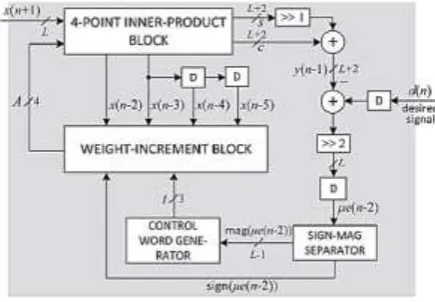
Fig. 5: Proposed structure of DA-based
LMS adaptive filter
The proposed structure of DA-based
adaptive filter of length N = 4 is shown in
Fig.5. It contains a four-point
inner-product block and a weight-increment
block in addition to additional circuits for
the computation of error value e(n) and
control word t for the barrel shifters. The
four-point inner-product block [shown in
Fig. 8] includes a DA table consisting of
an array of 15 registers which stores the
partial inner products yl for 0 < l ≤ 15 and
a 16 : 1 multiplexer to select the content of
one of those registers. Bit slices of weights
A = {w3l w2l w1l w0l} for 0 ≤ l ≤ L − 1
are fed to the MUX as control in LSBto-
MSB order, and the output of the MUX is
given to the carry-save accumulator
(shown in Fig. 2). After L bit cycles, the
carry-save accumulator shift accumulates
all the partial inner products and generates
a sum word and a carry word of size (L +
2) bit each. The carry and sum words are
shifted -added with an input carry “1” to
generate filter output which is
subsequently subtracted from the desired
output d(n) to obtain the error e(n). As is
the case in [5], all the bits of the error
except the most significant one are
ignored, such that multiplication of input
xk by the error is implemented by a right
shift through the number of locations
given by the number of leading zeros in
the magnitude of the error. The magnitude
of the computed error is decoded to
generate the control word t for the barrel
shifter. The logic used for the generation
of control word t to be used for the barrel
shifter is shown in Fig. 10. The
convergence factor μ is usually taken to be
O(1/N). Convergence factor has been
taken as μ = 1/N. However, one can take μ as 2−i/N, where i is a small integer. The
number of shifts t in that case is increased
by i, and the input to the barrel shifters is
pre-shifted by i locations accordingly to
reduce the hardware complexity. The
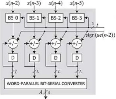
weightincrement unit [shown in Fig. 9] for
N = 4 consists of four barrel shifters and
four adder/subtractor cells. The barrel
shifter shifts the different input values xk
for k = 0, 1, ..., N − 1 by suitable number
the most significant one in the estimated
error). The barrel shifter produces the
desired increments that are to be added
with or subtracted from the current
weights. The sign bit of the error is used as
the control for adder/subtractor cells such
that, when sign bit is zero or one, the
barrel-shifter output is respectively added
with or subtracted from the content of the
corresponding current value in the weight
register.
Fig. 6: Structure of four-point
inner-product block
Fig. 7: Structure of weight-increment
block for N=4
IV. RESULTS
Fig 8: Block diagram of the proposed LMS
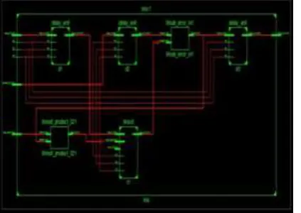
Fig 9: RTL of the proposed LMS adaptive
filter
Fig 10: Simulation result of the proposed
LMS adaptive filter
Fig 11: Summary report of the proposed
LMS adaptive filter
V. CONCLUSION
This paper presented the implementation
of carry-save accumulation scheme of
signed partial inner products for the
computation of filter output. It is well
implemented for Adaptive Filtering
applications. From the synthesis results, it
was found that the proposed design
consumes less power over our previous
DA-based FIR adaptive filter.
REFERENCES
[1] ApolinárioJr, José A., and Sergio L.
Netto. "Introduction to Adaptive Filters."In
QRD-RLS Adaptive Filtering, pp.
1-27.Springer US, 2009.
[2] B. Widrow and S. D. Stearns, Adaptive
signal processing. Prentice Hall,
Englewood Cliffs, NJ, 1985.
[3] S. Haykin and B. Widrow,
Least-mean-square adaptive filters.Wiley-Interscience,
Hoboken, NJ, 2003.
[4] Park, Sang Yoon, and Pramod Kumar
Meher. "Lowpower, high-throughput, and
low-area adaptive FIR filter based on
Systems II: Express Briefs, IEEE
Transactions on 60, no. 6 (2013): 346-350.
[5] D. J. Allred, H. Yoo, V. Krishnan, W.
Huang, and D. V. Anderson, “LMS
adaptive filters using distributed arithmetic
for high throughput,” IEEE Trans. Circuits
Syst. I, Reg. Papers, vol. 52, no. 7, pp.
1327–1337, Jul. 2005.
[6] P. K. Meher, ‘LUT Optimization for
Memory-Based Computation,’ IEEE Trans
on Circuits & Systems-II, pp.285-289,
April 2010.
[7] Haykin, Simon S. Adaptive filter
theory. Pearson Education India, pp.18,
1996.
[8] A. Croisier, D. Esteban, M. Levilion,
and V. Rizo, “Digital filter for PCM encoded signals US Patent 3, 777, 130,”
1973.
[9] S. Zohar, “New Hardware Realizations
of Nonrecursive Digital Filters,” IEEE
Transactions on Computers, vol. C-22, no.
4, pp. 328–338, 1973.
[10] A. Peled and B. Liu, “A New Hardware Realization of Digital Filters,”
IEEE Transactions on ASSP, vol. 22, no.
6, pp. 456–462, 1974.
Author’s Profile:
K. SIVA NAGA LEELA has
received her B.Tech Degree in
Electronic Communication
Engineering from Mallineni
Lakshmaiah Engineering college affiliated to
JNTU Kakinada in 2012 and pursuing M.Tech
degree in VESD(VLSI&ES) in Rise Krishna
Sai Gandhi Group of Institutions, Ongole
affiliated to JNTU Kakinada in 2019, AP,
India.
S.V.Ravi Kumar has received
his B.Tech in Electronics &
Communications Engineering
from QIS College of
Engineering & Technology, Ongole, and
M.Tech degree in ES & VLSI from A1 Global
College of Engineering & Technology.
Markapuram, JNTU Kakinada. He is dedicated
to teaching field from last 10+ Years. At
present he is working as Assistant professor in
RISE Krishna Sai Prakasam Group of
Institutions, Ongole, affiliated to JNTU