Reducing the output harmonics and the number components in high frequency distribution system by using a switched-capacitor-based cascaded multilevel inverter
K Prasada Rao
Associate professor, EEE department,
Christu Jyothi Institute of Technology and science, Jangaon, TS, India.
Abstract: The increase of frequency in AC transmission system has more advantages than low- or medium frequency distribution systems. In frequency ac Power Distribution System the high-Frequency inverter serves as source. Here the high frequency inverter is obtained with a switched-capacitor-based cascaded multilevel inverter is proposed in this work. The inverter is constructed by a combination of switched-capacitor and H Bridge inverter. The the conversion of series and parallel connections, the switched capacitor increases the number of voltage levels in the output. The harmonics in the output and the number of components can be significantly reduced by the increasing number of voltage levels in the output waveform. The symmetrical triangular waveform modulation with analog implementation is used in this circuit topology. The mathematical analysis, determination of circuit parameters is examined. The computer simulation results confirm the feasibility of proposed multilevel inverter.
Keywords: Cascaded H-Bridge inverter, high-frequency ac, multilevel inverter, switched capacitor
1. Introduction
than input voltage. By using this total harmonics are reduced because of the increased levels in the output voltage.
High-Frequency AC Power Distribution System becomes an alternative to dc distribution due to the lesser components and lower cost. The present inverter applications can be found in computer, telecom, electric vehicle and renewable energy micro grid [[1],[2]. However high-frequency AC Power Distribution System has to confront the challenges from large power capacity, high Electromagnetic Interference, and severe power losses [3]. In order to increase the power capacity, the most popular method is to connect the inverter output in series or in parallel. However, it is impractical for high-frequency inverter, because it is complicated to simultaneously synchronize both amplitude and phase with high frequency dynamics. Multilevel inverter is an effective solution to increase power capacity without synchronization consideration, so the higher power capacity is easy to be achieved by multilevel inverter with lower switch stress. Non polluted sinusoidal waveform with the lower Total Harmonic Distortion (THD) is critically caused by long track distribution in HFAC PDS. The higher number of voltage levels can effectively decrease total harmonics content of staircase output, thus significantly simplifying the filter design [4]. HF power distribution is applicable for small-scale and internal closed electrical network in Electric vehicle (EV) due to moderate size of distribution network and effective weight reduction [5]. The consideration of operation frequency has to make compromise between the ac inductance and resistance [6], so multilevel inverter with the output frequency of about 25 kHz is a feasible trial to serve as power source for high-frequency EV application. The traditional topologies of multilevel inverter mainly are diode-clamped and capacitor-clamped type [7], [8]. In this project the efficiency of the out voltage is increased to certain level. To overcome the above problem of two methods we are going for cascaded multi level inverter based on switched capacitor for high frequency AC power distribution system. In this project we want to increase the levels of output voltage at any cost without problem discussed above. We used two cascaded H-Bridge inverters and capacitors which, used increase the output voltage more than input voltage. By using this total harmonics are reduced because of the increased levels in the output voltage.
2. Fault diagnosis in multilevel converters
the conventional protection systems are passive devices such as fuses, overload relays, and circuit breakers to protect the inverter systems and the induction motors. The protection devices will disconnect the power sources from the multilevel inverter system whenever a fault occurs, stopping the operated process. Downtime of manufacturing equipment can add up to be thousands or hundreds of thousands of dollars per hour, therefore fault detection and diagnosis is vital to a company’s bottom line. In order to maintain continuous operation for a multilevel inverter system, knowledge of fault behaviors, fault prediction, and fault diagnosis are necessary. Faults should be detected as soon as possible after they occur, because if a motor drive runs continuously under abnormal conditions, the drive or motor may quickly fail.
3.Cascaded nine level inverter with nine-level output.
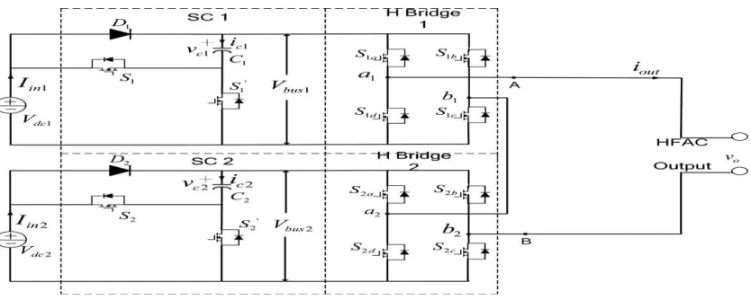
Fig .1 Nine Level Inverter for nine level output
The proposed circuit is made up of the switched capacitor and cascaded H-Bridge inverter. If the numbers of voltage levels obtained by switched capacitor and cascaded H-Bridge inverte are N1 and N2 , then the number of voltage levels is 2 ×N1×N2+1 in the entire operation cycle.Fig 1 shows the circuit topology of nine-level inverter (N1 =2, N2 = 2), where S1, S2, S1 , S2 as the switching devices of switched capacitor circuits (SC1 and SC2) are used to convert the series or parallel connection of C1 and C2 . S1a, S1b, S1c, S1d, S2a, S2b, S2c, S2dare the switching devices of cascaded H-Bridge. Vdc1 and Vdc2 are input voltage. D1 and D2 are diode to restrict the currents direction. Iout and vo are the output current and the
controlled by them. Vm 1c and Vm 2c are used to control the alternative operations of SC1 and SC2, respectively, and αi is the duration of voltage levels controlled by them. Thus, the drive signals of H-Bridge switches (S1a, S1b, S1c, S1d, S2a, S2b, S2c, S2d ) are phase-shifted pulse signals, while the drive signals of SC switches (S1, S2, S_1 , S_2 )are complementary pulse signals.
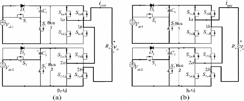
Fig . 2. Active circuits for different operation intervals in the operational modes
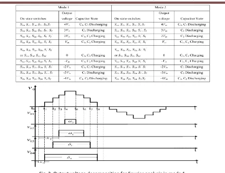
.The operations H-Bridge 1 is in freewheeling state, and H-Bridge 2 is in Fig. 2. Output voltage equals 2Vin because S1 and S2 are on, the capacitor C1 keeps charged to Vin and capacitor C2 is discharged. The voltages on Bus 1 and Bus 2 are Vin and 2Vin , respectively. The current flow of this time intervals shown in Fig(a). Similarly, the active circuit of t6 ≤ t <t7is shown in Fig (b) that has the same operations as t2 ≤ t <t3 . The second half-cycle (from t8 on) has the similar active circuits as the first half-cycle (t1 − t8 ), but the current will be circulated in the opposite direction to provide the negative output voltage. The relations of on-state switches and output voltage level are described in Table I, as well as operations of two modes are compared closely. Table I has ten working states for nine voltage levels. When the operation enters a new state from an adjacent state, only one power switch changes between on and off. The device stress in switching devices of H-bridge circuit is higher than that in SC circuit. It can also be found that the output voltage in Mode 1 is more stable than Mode 2 due to less discharging period of switching capacitor. Along with the up-down movement of modulation signals (Vm 1c, Vm 1b, Vm 2c, Vm 2b ), the output voltage of the proposed inverter is a controllable nine-level staircase. The duration of each voltage level is determined by the duty-cycle of SC circuit and the phase-shifted angle of H-Bridge circuit.
Fig. 3. Output voltage decomposition for Fourier analysis in mode 1.
Table.2 Components Comparison Of Proposed Inverter And Cascaded H-Bridge:
An n × 2 topology needs 2n – 2 capacitors, 2n + 8 switches, and 2 dc inputs; 2×n topology needs n capacitors, 6n switches, and n dc inputs. The traditional cascaded H-Bridge needs 8n switches and 2n dc inputs. With the same number of voltage levels, the proposed inverter needs less switching devices and inputs than the traditional cascaded H-Bridge. The fundamental frequency is 25 kHz that is the same as output frequency. It can be observed that the fundamental harmonic is significantly higher than the other harmonics. The magnitude of fundamental component is below 40 V for nine-level inverter.The calculated THD is 19.1% for 9-level inverter .It can be estimated that the harmonics can be further cut down along with the increasing number of voltage levels. Thus, the proposed inverter produces near sinusoidal staircase output, and two methods can make it more sinusoidal. One is to optimize the duration of voltage levels; the other one is to increase the number of voltage levels.
4. Computer simulation results
Fig.4 simulation circuit of nine level inverter
Fig 5. Nine level inverter output voltage waveform
5.Conclusion
In this proposed work, a switched capacitor based cascaded multilevel inverter with reduced total harmonic component was proposed. The nine level output compared with conventional cascaded multilevel inverter, the proposed inverter can decrease the number of switching components. A single carrier modulation technique with the low switching frequency was presented. The simulation results obtained confirms the feasibility of proposed circuit and modulation method. Comparing with cascade H-bridge, the number of voltage levels can be further increased by this method. The number of voltage levels increases two times in half cycle of nine level converter output. With the increase in the number of voltage levels, the harmonics are significantly reduced in the staircase output. Meanwhile, the magnitude control can be achieved by pulse width regulation of voltage level, so the proposed multilevel inverter can serve as HF power source with controlled magnitude and lesser harmonics. In this proposed work the nine level inverter was analyzed. The proposed inverter can be applied to grid-connected photovoltaic system and electrical network of EV, because the multiple dc sources are available easily from solar panel, batteries ,Ultra capacitors, and fuel cells.
References
*1+ S. Chakraborty and M. G. Simoes, “Experimental evaluation of active filtering in a single-phase high-frequency AC microgrid,” IEEE Trans. Energy Convers., vol. 24, no. 3, pp. 673–682, Sep. 2009. [2] R. Strzelecki and G. Benysek, Power Electronics in Smart Electrical Energy Networks. London, U.K.:
Springer-Verlag, 2008.
*3+ Z.Ye, P. K. Jain, and P. C. Sen, “A two-stage resonant inverter with control of the phase angle and magnitude of the output voltage,” IEEE Trans. Ind. Electron., vol. 54, no. 5, pp. 2797–2812, Oct. 2007.
[4] L. M. Tolbert, F. Z. Peng, and T. G. Habetler, “Multilevel PWM methods at low modulation indices,” IEEE Trans. Power Electron., vol. 15, no. 4, pp. 719–725, Jul. 2000.
*5+ C. C. Antaloae, J. Marco, and N. D. Vaughan, “Feasibility of highfrequency alternating current power for motor auxiliary loads in vehicles,” IEEE Trans. Veh. Technol., vol. 60, no. 2, pp. 390–405, Feb. 2011.
*7+ P. P. Rodriguez, M. M. D. Bellar, R. R. S.Mu˜noz-Aguilar, S. S. Busquets- Monge, and F. F. Blaabjerg, “Multilevel clamped multilevel converters (MLC),” IEEE Trans. Power Electron., vol. 27, no. 3, pp. 1055–1060,Mar. 2012.
[8] K. Ilves, A. Antonopoulos, S. Norrga, and H.-.P. Nee, “A new modulation method for the modular multilevel converter allowing fundamental switching frequency,” IEEE Trans. Power Electron., vol. 27, no. 8,pp. 3482–3494, Aug. 2012.
*9+ Y. Hinago and H. Koizumi, “A switched-capacitor inverter using series/ parallel conversion with inductive load,” IEEE Trans. Ind. Electron., vol. 59, no. 2, pp. 878–887, Feb. 2012.
*10+ M. S. W. Chan and K. T. Chau, “A new switched-capacitor boostmultilevel inverter using partial charging,” IEEE Trans. Circuits Syst. II: Exp. Briefs, vol. 54, no. 12, pp. 1145–1149, Dec. 2007.
*11+ K. K. Law and K. W. E. Cheng, “Examination of the frequency modulation and lifting techniques for the generalized power factor correction switched-capacitor resonant converter,” Int. J. Circuit Theory Appl., vol. 36, no. 7, pp. 839–855, Oct. 2008.
*12+ A. K. Gupta and A. M. Khambadkone, “A space vector modulation scheme to reduce common mode voltage for cascaded multilevel inverters,” IEEE Trans. Power Electron., vol. 22, no. 5, pp. 1672– 1681, Sep. 2007.