Static and Dynamic Analysis of Chassis
E.Bhaskar 1, T.Muneiah 2, Ch.Venkata Rajesh3
1,2,3 Assistant professor, Department Of Mechanical Engineering,Priyadarshini college of
engineering & Technology, Kanuparthipadu, SPSR Nellore-4.
ABSTRACT
In the present scenario, the automotive industry has been one of the rapid growing industries and is facing heavy competition from the competitors. This necessitates the need to work on various functional aspects of the automobile, starting from chassis design to aesthetic design. As a part of this, the present work aims to study the static characteristics of automobile chassis.
The chassis acts as a skeleton on which, the engine, wheels, axle assemblies, brakes, suspensions etc. are mounted. The chassis receives the reaction forces of the wheels during acceleration and braking and also absorbs aerodynamic wind forces and road shocks through the suspension. So the chassis should be engineered and built to maximize payload capability and to provide versatility, durability as well as adequate performance.
All real physical structures, when subjected to loads or displacements, behave dynamically. The additional inertia forces, according to Newton’s second law, are equal to the mass times the acceleration. If the loads or displacements are applied very slowly, then the inertia forces can be neglected and a static load analysis can be justified, but in reality the loads are dynamic in nature. Hence, in this work, an effort is made to investigate the static and dynamic response of truck chassis due to road undulations.
The geometric modeling of the various components of the chassis is carried out in part mode as 3D models using Pro/ENGINEER 2001 software. The section properties,viz, cross-sectional area details of the 3D modeled parts are estimated using the modeling software. The above properties have been used as input while performing the finite element analysis using ANSYS7.1 software.
The finite element model of the chassis is created using ANSYS 7.1 package. Static analysis is done for vehicle on a plain road and bump conditions. The model is subjected to static analysis for all the conditions specified. The stress and deflection plots are determined.
Keywords:
1.0 INTRODUCTION
1.1 ROLE OF CHASSIS IN AUTOMOTIVES
Every vehicle body consists of two parts; chassis and bodywork or superstructure. The chassis is the framework of any vehicle. Its principal function is to safely carry the maximum load for all designed operating conditions. It must also absorb engine and driveline torque, endure shock loading and accommodate twisting on uneven road surfaces. The chassis receives the reaction forces of the wheels during acceleration and braking and also absorbs aerodynamic wind forces and road shocks through the suspension. So the chassis should be engineered and built to maximize payload capability and to provide versatility, durability as well as adequate performance. To achieve a satisfactory performance, the construction of a heavy vehicle chassis is the result of careful design and rigorous testing.
It should be noted that this ‘ladder’ type of frame construction is designed to offer good downward support for the body and payload and at the same time provide torsional flexibility, mainly in the region between the gearbox cross member and the cross member ahead of the rear suspension. This chassis flexing is necessary because a rigid frame is more likely to fail than a flexible one that can ‘weave’ when the vehicle is exposed to arduous conditions. A torsionally flexible frame also has the advantage of decreasing the suspension loading when the vehicle is on uneven surfaces.
The chassis which is made of pressed steel members can be considered structurally as grillages. It acts as a skeleton on which, the engine, wheels, axle assemblies, brakes, suspensions etc. are mounted. The frame and cross members form an important part of the
chassis. The frame supports the cab, engine transmission, axles and various other components. Cross members are also used for vehicle component mounting, and protecting the wires and tubing that are routed from one side of the vehicle to the other. The cross members control axial rotation and longitudinal motion of the main frame, and reduce torsion stress transmitted from one rail to the other.
1.2 TYPES OF FRAMES
(i) Ladder frame
This is a common type of frame, in which all the transverse (lateral) connecting members are straight across in the plan view. In this type, the frame resembles a ladder as the name implies. (ii) Perimeter frame
A perimeter frame consists of welded or riveted or bolted frame members around the entire perimeter of the body. In this, the frame members are provided underneath the sides, as well as for the suspension and related components.
(iii) Sub-type frame
A sub-type frame is a partial frame often used on unit-body vehicles to support the power train and suspension components. Normally the various components are bolted directly to the main frame. But many a times, these components are mounted on a separate frame called sub-frame. This sub-frame is further supported by the main frame at three points. In this way the components are isolated from the effects of twisting and flexing of the main frame. The advantages of sub-frames are:
The mass of the sub-frame alone helps to damp vibrations
(iv) Unit body construction
Unit body construction is a design that combines the body and the structure of the frame. In this, the body itself supports the engine and driveline components. In this type of construction, heavy side members used in conventional construction are eliminated and the floor is strengthened by cross-members and the body, all welded together. In some cases the sub-frames are also used along with this type of construction.
(v) Space frame construction
Space frame construction consists of formed sheet used to construct a framework for the entire vehicle. This vehicle is also drivable without a body.
Conventional chassis frame
Steel pressing of channel or box section form the side (frame) members. They are connected together by means of cross members (made of channel or box sections) so as to form a rigid but light frame work. The cross members are also used to mount the chassis components on them. These transverse members are usually riveted or welded to the side members, with the help of special enlarged flanges known as gusset plates.
At the front and rear ends, the longitudinal members are tapered in depth (beams of the uniform strength for minimum weight).The side rails at the front end are brought closer together when viewed in plan in order to provide space for the free turning of the steered wheels. It is usual to arch (upswept) the side rails towards the front and rear ends, in order to provide sufficient space for the vertical movement of the axles during its springing action while travelling on a rough road.
Near the front and rear ends, special brackets in the form of metal forgings are welded to form the bearing
location for the spring shackles. At the rear end of the frame, it is usual to provide one or more cross strut members of channel or tubular section in order to take the rear spring forces tending to distort the frame and to provide an increased amount of torsional rigidity.
To provide a larger stability to the vehicle, the height of the body work and hence the centre of gravity should be kept as low as possible. Hence the frame is kept lowered as much as possible between the front and rear axles. In the case of heavy vehicles, full length box section side rails and cross members made from medium carbon to low carbon alloy steel pressings are welded together to get chassis frame with higher strength and stiffness.
It has a diagonally braced central portion also, to carry the universal joint bearing block. The front end of the side members have flattened ends and are designed to take bumper brackets. The engine is mounted at the front, on rubber block mountings. Since the heavy duty vehicle frames have straight side rails and cross members, similar to ladder geometry-wise, this type of frame is known as ladder type frame.
(vi) Frameless Chassis (Integral Chassis Frame and Body)
Developments in the art of welding and pressing of large steels sheets into complex shapes, have allowed the integration of the frame structure and the body work as a single unit, so as to achieve a very light but a stiff structure for a given material content. This chassis cum body construction is also called as ‘frameless chassis’
Combining the sides and cross
members with the floor panel and body structure, constitutes a useful load bearing structural component which also results in considerable weight reduction.
Basically, the structure includes integration of an under frame consisting of floor panel and the cross members, the bonnet wings(sides), steel facial at front to receive the engine, rear luggage compartment or tray and other structural members behind the rear seat portion. They are all welded together as one single assembly.
The floor surfaces are ribbed and dished for additional strength and rigidity. The pressed steel body shell is attached to the chassis frame by welding. In order to carry the engine and the front suspension, a sub frame is also attached to the front of the body shell.
To mount the engine, suspension members and bumpers, the structure is further extended at the front and reinforced at the rear. A very low carbon steel (less than 0.1% carbon) having extremely good ductility is used for pressing of the panels which allows easy forming.
Since the structural panel members are made of low strength materials, they are stiffened by sections formed out of thin steel sheets into intricate sections by spot welding.
To avoid reduction of strength of the given chassis due to rusting, some special treatment against corrosion is given. For this purpose the entire body is preferably immersed in rust inhibiting bath or protective solution to seal all joints.
This is further enhanced by coating both the inner and outer surfaces with anti corrosive primer paint. A sound damping material is stuck on the inside of the
panel to avoid panel vibration which causes an objectionable drumming sound.
Advantages:
o The body itself becomes a load carrying beam
o The load is diffused through the entire structure so that body becomes lighter retaining the strength
o It is easy to assemble the different body panels into a unitized structure
o During collision the impact loads are absorbed by the body crumbles and there by the shock load transferred to the passengers is reduced to a large extent
o Disadvantages:
o During the accidents the body panel receives major impact loads crushing into bundle of steel plate mass
o Usually, the damage to the body of an integral chassis construction is considerably large, many a times beyond repair o This makes the servicing
costs quite high
(vii) Tubular Chassis
The flat frame is by no means the best form to resist torsion and for this reason certain firms adopted a tubular chassis. Hence, in the flat frame type of chassis the principal members, namely the engine and transmission parts are stressed heavily by road shocks and reaction torques.
separately and each is driven by a shaft
from the differential gear. Two cantilever springs and a common connecting leaf spring situated below the differential casing arrangement gives greater strength in torsion and bending in the longitudinal sense although it is not so convenient as the flat frame for body mounting. Farm tractors are usually made of tubular chassis frame of rectangular type.
2.0 MODELING OF CHASSIS
2.1 GEOMETRIC MODEL OF
CHASSIS
Geometric modeling of the various components of chassis has been carried out in part mode as 3-D models using Pro/ENGINEER 2001. The properties, viz., cross-sectional area, beam height and area moment of inertia of these 3-D modeled parts are estimated in Pro/ENGINEER 2001. These properties have been used as input while performing the finite element analysis using ANSYS 7.1 software.
Fig.1 Model of chassis assembled in PRO-Engineering
2.2 MATERIAL
Alloy steel material is generally used for the manufacture of the chassis and the properties of the material are shown in Table .1
Heavy-duty chassis are usually manufactured with either frame rails of steel or aluminum alloy. Each material must be handled in a specific manner to
assure maximum service life. Many heavy-duty trucks are presently manufactured with frame rails of mild steel high-strength low-alloy steel or heat treated steel. Material thickness increases, as the truck’s intended duty becomes more severe. The depth of the rail also increases with duty severity. The on-road tractor rails will usually be less, than the damper rails.
Table .1 Properties of alloy steel
Sl.no. Properties Value
1
Modulus of rigidity 210 GPa
2
Poisson’s ratio 0.3
3
Mass density 7800 kg / m
3
4
Yield strength 500 MPa
5
Element type BEAM188
3.0 STATIC ANALYSIS
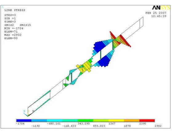
The deflection and stress pattern in the model of the chassis is obtained by performing static analysis. The results of model are shown in Tables.2 and 3 and the general pattern of deflection, stress
and strain are shown in Fig. 2, Fig. 3 and Fig. 4 respectively. The design stress for the alloy steel material of which the chassis is made is 500 MPa. Based on this, the factor of safety is estimated as shown in Table .2.
Table .2 Static deflections in chassis
Condition\Model Maximum Deflection (mm)
Vehicle On Plain Road 0.23 Front Wheels On Bump 4.15 Back Wheels On Bump 4.1
Side Wheels On Bump 1.53
Diagonal Wheels On Bump 1.1
Table .3 Static stresses in chassis
Condition\Model Maximum bending stress(MPa)
Vehicle On Plain Road 6.53 Front Wheels On Bump 16.6 Back Wheels On Bump 15.4 Side Wheels On Bump 10 Diagonal Wheels On Bump 9
Fig. 2 Stress developed on chassis
Fig. 3 Maximum strain developed on chassis
Table .4
Results
MAXIMUM DEFLECTION
0.236M M
MAXIMUM STRESS
16.6MPa
MAXIMUM STRAIN
0.22E-6
FACTOR OF SAFETY
30.12
4.0 DYNAMIC ANALYSIS
4.1 Modal Analysis
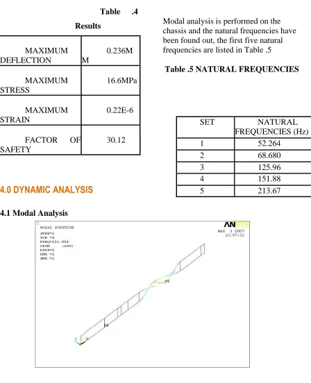
Modal analysis is performed on the chassis and the natural frequencies have been found out, the first five natural frequencies are listed in Table .5
Table .5 NATURAL FREQUENCIES
Fig.5 Fourth Mode Shape
The natural frequencies for model range from 52Hz to 213Hz . Table .5 indicates that the highest forcing frequency is in the range 30-40 Hz, whereas the fundamental natural frequency for models 52 Hz. Hence the
fundamental natural frequency is well above the forcing frequency range, which shows that the chassis is safe from resonance point of view.
SET NATURAL FREQUENCIES (Hz)
1 52.264
2 68.680
3 125.96
4 151.88
5.0 CONCLUSION
• Modelling has been done in solid mode and the section properties of different models are estimated using Pro/ENGINEER 2001.
• The deflection and stress pattern in the model of the chassis is obtained by performing static analysis. However, include steady inertia loads (such as gravity and rotational velocity), and time-varying loads are also included that are approximated as static equivalent loads.
• Maximum Deflection of chassis was found to be .2mm and maximum stress was found to be 16.6MPa.
• The design stress for the alloy steel material of which the chassis is made is 500 MPa. Based on this, the factor of safety is estimated as 30.12.
• We can do case studies by changing the cross section types of both longitudinal and cross beams of the chassis.
• By altering the locations of the cross members, we can do a number of case studies.
• Material of chassis can be altered
o Alloys of steel for Heavy duty chassis.
o Alloys of Aluminum for light weight chassis.
6.0 REFERENCES
1. Theory of Vibrations by Grover.
2. “Finite Element analysis”, by Krishnamoorthy. 3. Finite and boundary methods in engg by O.P.Guptha
4. Pro/Engineer for Engineers & Designers by Prof. Sham Tickoo 5. Autar K. Kaw, "Mechanics of Composite Materials", CRC press, 1997.
6. Ahid D. Nashif, David I. G. Jones and John P. Henderson, “Vibration Damping”, John Wiley & Sons Publication, 1985, Newyork.
7. C. T. Sun and Y. P. Lu, "Vibration Damping of Structural Elements", Prentince Hall PTR, New Jeresy, 1995.
8. T. E. Alberts and Houchun Xia, “Design and Analysis of Fiber Enhanced Viscoelastic Damping Polymers”, Journal of Vibration and Acoustics, Vol. 117, October 1995, pp. 398-404.