317 | P a g e
COMPARATIVE STUDY OF DIFFERENT
TOPOLOGIES OF FIVE LEVEL INVERTER FOR
HARMONICS REDUCTION
Mahtab Alam
1,
Mr. Jitendra Kumar Garg
2 1Student, M.Tech,
2Associate Prof., Department of Electrical & Electronics Engineering, Alfalah
University, (India)
ABSTRACT
The power electronics device which converts DC power to AC power at required output voltage and frequency
level is known as inverter. The voltage source inverters produce an output voltage or a current with levels either
0 or +ve or-ve V dc. They are known as two-level inverters. Multilevel inverter is to synthesize a near sinusoidal
voltage from several levels of dc voltages. Multilevel inverter has advantage like minimum harmonic distortion.
Multi-level inverters are emerging as the new breed of power converter options for high power applications.
They typically synthesize the stair case voltage waveform (from several dc sources) which has reduced
harmonic content. This thesis compares three different topologies of inverters (5- level inverter, Diode clamped
inverter, 5 level Flying capacitor clamped inverter and 5-level Cascaded H-bridge inverter). In this model of
five-level single phase Diode clamped inverter, Flying capacitor clamped inverter and Cascaded H-bridge
inverter has been developed using MOSFETS IGBT. Gating signals for these MOSFETS have been generated by
designing comparators. In order to maintain the different voltage levels at appropriate intervals, the conduction
time intervals of MOSFETS have been maintained by controlling the pulse width of gating pulses ( by varying
the reference signals magnitude of the comparator ). The results of are compared with simulation results.
Simulation models (designed in SIMULINK) have been developed up to five levels and THD in all the cases
have been identified.
Keywords: Multilevel, Cascade, Harmonics, Modulation, MATLAB/SIMULINK, THD.
I. INTRODUCTION
318 | P a g e
The elementary concept of a multilevel inverter to achieve higher power is to use a series of power semiconductor switches with several dc sources to perform the power conversion by synthesizing a staircase voltage waveform. Capacitors, batteries, and renewable energy sources can be used as the multiple dc voltage sources. The multilevel inverter output voltage has less number of harmonics [2, 3]. The most common MLI topologies are classified into three types: neutral point clamped (NPCMLI) or diode clamped MLI (DCMLI), flying capacitor MLI (FCMLI), and Cascaded HBridge MLI (CHBMLI). The basic topologies of the MLI are shown in Fig.1. particularly DCMLI five-level structure have a wide popularity in motor drive applications besides other multilevel inverter topologies. However, it would be a limitation of complexity and number of clamping diodes for the DCMLIs, as the level exceeds. The FCMLIs are based on balancing capacitors on phase buses and generate multilevel output voltage waveform clamped by capacitors instead of diodes. The FCMLI topology also requires balancing capacitors per phase at a number of (m - 1) * (m -2)/2 for an m-level inverter and it will cause to increase the number of required capacitor in high level inverter topologies and complexity of considering DC-link balancing [1]. Nowadays, the multilevel inverters have become more attractive for researchers and manufacturers due to their advantages over conventional five level pulse width modulated (PWM) inverters. They offer improved output waveforms, smaller filter size, low EMI, lower total harmonic distortion (THD). Multilevel inverter topology has the least components for a given number of levels. Cascaded H-BridgeMLI topology is based on the series connection of H-bridges with separate DC sources. Since the output terminals of the Hbridges are connected in series, the DC sources must be isolated from each other. The need of several sources on the DC side of the inverter makes multilevel technology attractive for photovoltaic applications.
319 | P a g e
(b)
(c)
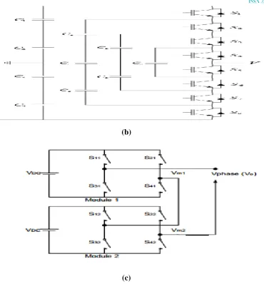
Fig 1. Multi Level Inverter Topologies: a) Five level DC-MLI, b) Five Level FC-MLI, c) Five
Level CHB-MLI
II. BASIC OPERATING PRINCIPLE
2.1 Five Level DC-MLI
The most commonly used multilevel topology is the diode clamped inverter, in which the diode is used as the clamping device to clamp the dc bus voltage so as to achieve steps in the output voltage. Thus, the main concept of this inverter is to use diodes to limit the power devices voltage stress. The voltage over each capacitor and each switch is Vdc. An n level inverter needs (n-1) voltage sources, 2(n-1) switching devices and (n-1) (n-2) diodes. By increasing the number of voltage levels the quality of the output voltage is improved and the voltage waveform becomes closer to sinusoidal waveform. A five level DC-MLI is shown in fig1.a.
2.2 Five Level FC-MLI
320 | P a g e
(2n – 2) switches will use (n – 1) number of capacitors in order to operate. Fig1.b. shows a five level flying capacitor multilevel inverter.
2.3 Five Level CHB-MLI
The concept of this inverter is based on connecting H-bridge inverters in series to get a sinusoidal voltage output. The output voltage is the sum of the voltage that is generated by each cell. The number of output voltage levels are 2n+1, where n is the number of cells. The switching angles can be chosen in such a way that the total harmonic distortion is minimized. One of the advantages of this type of multilevel inverter is that it needs less number of components comparative to the Diode clamped or the flying capacitor, so the price and the weight of the inverter is less than that of the two former types. Fig.1.c. shows an five level cascaded H-bridge multilevel inverter.An n level cascaded H-bridge multilevel inverter needs 2(n-1) switching devices where n is the number of the output voltage level.
III. CONTROL TECHNIQUE
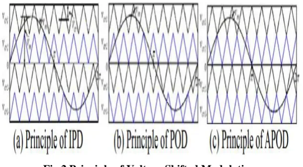
Voltage shifted modulation is way based on the carrier modulation. If the DC side capacitor voltage is equal to four, the carrier number is m-1 when five level diode clamped inverter level number is m. all of these carriers have the same frequency and the same amplitude. This ( m-1 ) a triangular carrier in the space is distributed vertically, and the occupied area is continuous, with each other closely connected, symmetrically distributed on the horizontal axis on both sides, and then with a sinusoidal modulation wave are compared, to generate a trigger pulse. Voltage shifted modulation mode have three kinds of pattern: with phase array ( In ① -phase
Disposition, IPD ); anti ② -phase arrangement ( Phase Opposition Disposition, POD ); alternately ③ reverse phase array ( Alternative Phase Opposition Disposition, APOD ). They work as shown in Figure 2 below.
Fig 2.Principle of Voltage Shifted Modulation.
321 | P a g e
Table 1. Switching State of Five Level DC-MLI
Table 2. Switching State of Five Level FC-MLI
Vo
S1 S2 S3 S4 S1' S2' S3' S4'
Vdc
1
1
1
1
0
0
0
0
3VdC/4 0
1
1
1
1
0
0
0
Vdc/2
0
0
1
1
1
1
0
0
Vdc/4
0
0
0
1
1
1
1
0
0
0
0
0
0
1
1
1
1
Table 3. Switching State of Five Level CHB-MLI
IV. SIMULATION AND RESULTS OF THE THREE TOPOLOGIES
322 | P a g e
(b)
(c)
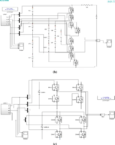
Fig 2. Simulink Model of Multi Level Inverter Topologies: a) Five Level DC-MLI, b) Five Level
FC-MLI, c) Five Level CHB-MLI
To verify that the proposed inverters implementations simulations were performed by using MATLAB/SIMULINK as shown in fig2. It also helps to confirm the PWM switching strategy . The parameters are chosen as under:
DC voltage (Vdc) = 100 V Modulation index (Ma) = 0.8 Sampling time = 2e-6.
323 | P a g e
(a)
(b)
(c)
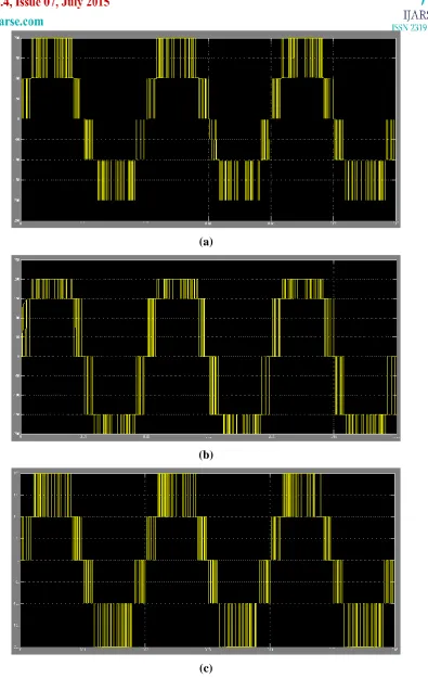
Fig 3. Output Voltage of Multi Level Inverter Topologies: a) Five Level DC-MLI, b) Five Level
324 | P a g e
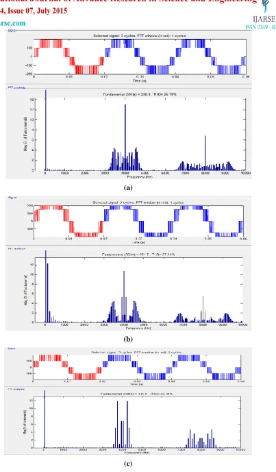
(a)
(b)
(c)
Fig 4. FFT Analysis of Multi Level Inverter Topologies: a) Five Level DC-MLI, b) Five Level
325 | P a g e
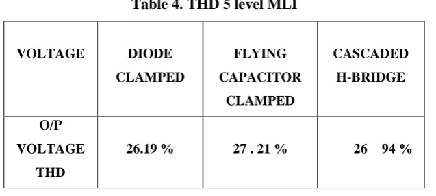
Table 4. THD 5 level MLI
VOLTAGE DIODE
CLAMPED FLYING CAPACITOR CLAMPED CASCADED H-BRIDGE O/P VOLTAGE THD
26.19 % 27 . 21 % 26 94 %
V.CONCLUSION
This work has presented several topologies for multilevel inverters (MLI), some of them well known with applications on the market. Every topology have been described in detail. Several modulation techniques have also been presented which are to be used with the presented topologies. We hereby conclude that Multi-level inverters is a very promising technology in the power industry. In this project, the advantages and applications of Multi-Level Inverters are mentioned and a detailed description of different multi-level inverter topologies is presented. Single Phase H-Bridge Inverter, Diode led and Flying capacitor multi level inverter functioning is realized virtually using MATLAB SIMULINK.
A detailed Multi-Level Inverter is presented from which we concluded that the harmonic content is greatly reduced in Multi-Level Inverter and the Cascaded H-Bridge Inverter topology has advantage over the other two as it requires less number of components as compared to the other two types of inverters and so its overall weight and price is also less.
REFERENCES
[1] “Power Electronics Circuits, Devices & Applications” , Muhammad H. Rashid, Third Edition, Prentice Hall India.
[2] Zhong Du, Leon M. Tolber, Burak Ozpineci, John N. Chiasso, DC-AC Cascaded HBridge Multilevel Boost Inverter With No Inductors for Electric/Hybrid Electric Vehicle Applications. 2009, Boise state university
[3] Martin Veenstra, INVESTIGATION AND CONTROL OF A HYBRID ASYMMETRIC
MULTI-LEVEL INVERTER FOR MEDIUM-VOLTAGE APPLICATIONS, 2003, Lausanne, EPFL
[4] L.M. Tolbert, F.Z. Peng, D.J. Adams, J.W. Mckeever, Multilevel inverters for large automotive electric drives, 1997, Darborn, Michigan
[5] K.T. Chau, Y.S. Wong, Overview of power management in hybrid electric vehicles, 2002, Energy conversion and management 43
326 | P a g e
[7] Fang Z. Peng, A Generalized Multilevel Inverter Topology with Self Voltage Balancing, IEEE transaction on Industry applications, Vol. 37, 2001
[8] Leon M. Tolbert, John Chiasson, Keith McKenzie, Zhong Du, Elimination of harmonics in a multilevel converter with non equal DC sources, IEEE transaction on Industry applications, Vol.41, 2005 [9] José Rodríguez, Jih-Sheng Lai, Fang Zheng Peng, Multilevel Inverters: A Survey of Topologies, Controls and Applications, IEEE transaction on Industry Electronics, Vol.49, 2002
[10] Leon M. Tolbert, Fang Z. Peng, Multilevel Converters as a Utility Interface for Renewable Energy Systems, Power engineering society summer meeting, 2000, IEEE
[11] Leon M. Tolbert, Fang Zheng Peng, Tim Cunnyngham, John N. Chiasson, Charge balance control schemes for cascade multilevel converter in hybrid electric vehicles, IEEE transactions on industrial electronics, Vol.49, 2002
[12] John N. Chiasson, Leon M. Tolbert, Keith J. McKenzie, Zhong Du, Control of a multilevel inverter using resultant theory, IEEE transaction on control systems technology, Vol.11, 2003
[13] D. Grahame Holmes, Thomas A.Lipo, Pulse width modulation for power converters, 2003 by Wiley interscience Inc.
[14] “Linear Integrated Circuits”, D.roy Choudary, Shail B.Jain, Second Edition, New Age International Publishers.
[15] “Multi-level Converter-A New Breed of Power Converters”, Jih-Sheng Lai and Fang Zheng Peng, IEEE Trans. Ind, Applicant Vol.32