Division III
A PARAMETRIC STUDY ON WELDING PROCESS SIMULATION
FOR MULTI-PASS WELDS
Won Dong Park1, Young Jin Oh2, Ji Hoon Kim3, and Chi Bum Bahn4
1
Graduate Student, School of Mechanical Engineering, Pusan National University, Korea 2
Principal Researcher, Power Engineering Research Institute, KEPCO E&C, Korea 3
Assistant Professor, School of Mechanical Engineering, Pusan National University, Korea 4
Assistant Professor, School of Mechanical Engineering, Pusan National University, Korea
ABSTRACT
Primary Water Stress Corrosion Cracking has been occurring in major welds of nuclear power plants. This phenomenon could reduce the equipment integrity and reliability. Tensile welding residual stress is one of the major causes of PWSCC. Therefore, many attempts have been trying to measure residual stress of welds or predict it using finite element analysis (FEA). There are some FEA methodologies to predict the residual stress. However, it is doubtable whether results of analysis are consistent to each other. In this study, effects of heat input methods and bead generation methods on the residual stress for multi-pass Alloy 82/182 welds were mainly analyzed by performing two-dimensional simulation using commercial FEA software, ABAQUS. Two heat input methods were considered: the heat flux method and the temperature boundary condition method. Although results of thermal analysis between two heat input methods were slightly different, distributions of the residual stress were similar. Because the areas exposed to high temperature were similar and the strength of the material was very low in high temperature (above the 1000 oC), the effects of the weld bead temperature were insignificant. Two weld bead generation methods were also considered: the element birth method and the quiet element method. The distribution of the residual stress was similar to each other. However, gaps and overlaps occurred on the welding boundary surfaces as the element birth method was applied. The quiet element method is more suitable for a large deformation model in order to simulate a more accurate weld shape.
INTRODUCTION
It is well known that the deformation and residual stresses caused by the interaction between welding variables, high-temperature behavior, and constraining conditions can reduce the integrity of the structure and shorten the service life (Kim and Jin, 2003). Finite element analysis (FEA) methodologies have been used to simulate the welding process. However, because of the difficulty in simulating the heat transfer process and the high temperature material behavior, most of the results of welding residual stress analysis differ from the actual measured values (Kim and Jin, 2003). Since the weld residual stress is determined by various parameters such as initial temperature of molten beads, heating time, cooling time, cooling conditions, and boundary conditions, the analysis results can be changed according to the input parameters (Song et al., 2008). For this reason, round robin studies organized by Electric Power Research Institute (EPRI) (Broussard, 2015a) or United States Nuclear Regulatory Commission (USNRC) (Benson et al., 2014) were conducted for the plates, cylinders and nozzle. The round robin study was also conducted on the nuclear nozzle welds in Korea (Song et al., 2009). In this study, to investigate the effects of heat source input methods and welding bead generation methods on the residual stress, the cylinder model (Phase 1b, C -3) in EPRI MRP-316 (Broussard, 2015a) was analyzed using a commercial FEA program, ABAQUS 2016 (Dassault Systems, 2015).
exponentially decreases with time, a combination of the volumetric and surface heat fluxes (Song et al., 2008; Song et al., 2009; Bae et al., 2012), and a temperature boundary condition method in which a temperature (about 1800 oC) above the melting point is input to the weld bead for a certain period of time (Bae et al., 2012; Kim et al., 2015). In the previous study (Song et al., 2009) it showed no significant difference whether the volumetric heat flux was combined with the surface heat flux or not. Therefore, in this study, the volumetric heat flux method (hereinafter “heat flux method”) and the temperature boundary condition method (hereinafter “temperature method”) were selected and the analysis results were compared.
On the other hand, the element birth method as the method of generating weld beads has been mainly applied (Brickstad and Josefson, 2008; Lindgren, 2001), in which weld beads are sequentially stacked up by using a model change option. Since this method requires relatively low analysis cost and similar to the actual welding process, it has been mainly used. However, when this method is applied, the node is regenerated at the initial position where the modeling is performed. Therefore, if the analysis is accompanied by the deformation, the weld bead element to be regenerated and the existing deformed weld element can overlap at the interface. Brickstad and Josefson (2008) argued that when applying the element birth method, a numerically-induced large element distortion may occur at the interface between the already welded and deformed bead and the newly welded bead. In other words, the element birth method can be applied to the stress analysis of a model in which the deformation due to the weld is small, but the element distortion can be significant in the stress analysis of the model accompanied with considerable deformation.
Brickstad and Josefson (2008), Lindgren (2001) and Yaghi et al. (2006) proposed a quiet element method, in which to avoid the displacement and strain mismatch at the boundary nodes between the base metal and weld material, reduced elastic modulus (E: 103 MPa) and yield stress (σy: 10 MPa) were applied to all weld beads at the certain temperature (1800 oC in this study), and then each bead was activated sequentially by applying normal material properties and temperature distributions. Although the inactive state of the mesh network can be slightly affected and the analysis cost is relatively high, it is possible to avoid the overlapping or distortion problem. It has an advantage that it can be applied to an analysis model having relatively large deformation. Therefore, in this study, the effects of the weld bead generation methods on the weld residual stress and deformation of weld zone are considered by comparing analysis results of models with the element birth method and the quiet element method.
ANALYSIS METHOD
Analysis Model
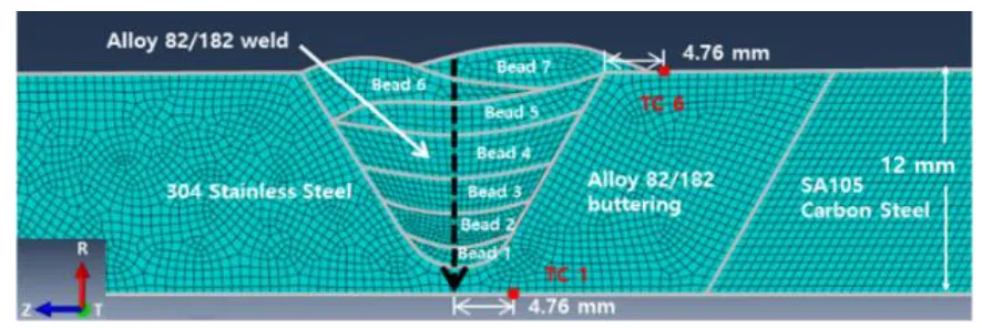
Figure 1. Axisymmetric finite element model of the cylinder (Park et al., 2017).
Material Properties
Thermal and mechanical properties of Alloy 82/182, 105 carbon steel, and 304 SS (or 316 SS) summarized in MRP-317 (Broussard, 2015b) were used for the analysis. The melting points of Alloy 82 and 105 carbon steel/304 SS are assumed to be 1345 oC and 1500 oC, respectively. The actual material has a stress relaxation phenomenon at a high temperature (about 850 oC or more (Song et al., 2008) in the case of ordinary steel), and the elastic modulus, yield stress, and hardening modulus become considerably low and the material cannot have load-carrying capacity until it is cooled (Yaghi et al., 2013). In the stress analysis, the materials in the molten state is assumed to be a solid material, but it is impossible to actually measure the elastic modulus and yield stress of the molten material. Therefore, the elastic modulus and the yield stress of the molten materials in the analysis should be significantly lower than them of the solid materials, and the input values should not interfere with the numerical convergence. It was confirmed that when the elastic modulus, the yield stress and the yield strain value of the molten materials were assumed to be 103 MPa, 10 MPa, 10-2 respectively, the stress analysis was carried out properly.
Heat Transfer Analysis Method
Two-dimensional axisymmetric heat transfer analysis was performed using two heat source input methods. The element birth method was applied as a weld bead generation method by using the ABAQUS model change option (Elcoate, 2015). The different natural convection conditions (convective heat transfer coefficient h = 10 or 15.8, 28.4 W/m2∙ oC) on the interface between the metal part and the air showed little effect on the residual stress distribution (Song et al., 2009). However, in order to simulate the effect of surface temperature (T, oC) on the convection and radiation heat transfer more realistically, Equation (1) (Brickstad and Josefson, 2008; Yaghi et al., 2006) was applied, which considers convective and radiation heat transfer effects simultaneously.
(1)
As the first heat source input method, the heat flux method was applied. The volumetric heat flux, as described in Equation (2), was exponentially decreased and inversely proportional to the bead volume (Aw) (Broussard, 2015a and 2015b).
where q(J/s·mm3) is the power density, t(s) is heating time, L(mm) is a characteristic length, S(mm/s) is a torch speed, E is a scale parameter, V(volt) is a voltage, and A(ampere) is current. This method is a simplification of the three-dimensional heat source model proposed by Goldak et al. (1984) to a two-dimensional heat source, which was proposed by Rudland et al. (2007). Although this simplification relatively well simulates the heat transfer effect in the welding arc, when the shape of the weld bead becomes flat, the temperature of the bead may not be sufficiently raised. Table 1 is the welding variables for the heat flux method. The variables for each bead were determined so that the calculated temperature distribution became similar to the measured ones at several locations (See TC 1 and TC 6 locations in Fig. 1). The total power (VA) for each bead was referred to the values in MRP-316.
Table 1: Welding variables for the heat flux method.
Bead number
Aw (mm 3
) E VA(J/s) L(mm) S(mm/s)
1 127.25 1.725 1649
50.8 2.54
2 297.43 1.4 1739
3 494.28 1.38 2256
4 605.03 1.05
3135
5 530.86 1.27
6 484.12 1.21
7 439.17 0.92
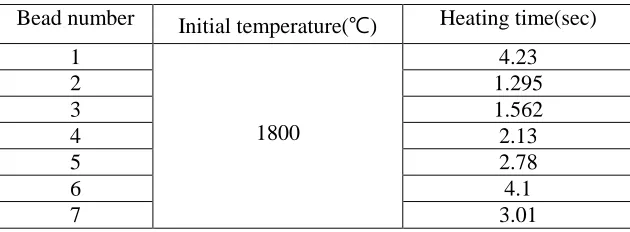
As the second method, the temperature method (Bae et al., 2012; Kim et al., 2015) was applied. The initial temperature was selected as 1500 oC, but the heating time for each molten bead was determined considering the maximum temperature of each pass measured by a thermocouple at a specific position in actual welding, as listed in Table 2. The temperature method is relatively insufficient to simulate the effect of heat transfer in the welding arc, but it has the advantage of being able to input the same temperature in all weld bead regions. In both methods, the weld bead was stacked and cooled to room temperature (about 21 oC) sufficiently for 104 sec.
Table 2: Welding variables for the temperature method.
Bead number Initial temperature(℃) Heating time(sec)
1
1800
4.23
2 1.295
3 1.562
4 2.13
5 2.78
6 4.1
7 3.01
Stress Analysis Conditions
RESULTS & DISCUSSION
Heat Source Input Methods
In order to compare the welding residual stress analysis results according to the heat source input methods and the bead generation methods, four kinds of finite element analysis models are classified (FEA Model A, B, C, D). Figure 2 shows the residual stress distribution along the center line in the circumferential and the axial directions. For the comparison of the tendency, the finite element analysis results in MRP-316 with the isotropic material hardening model are also shown in Fig. 2. The four FEA models showed a slight difference in the absolute stress level, but both the circumferential and axial weld residual stresses showed similar trends along the thickness direction. It should be noted that the information of the weld bead shape and the heat input amount of the MRP-316 FEA model is not available in detail, so that it may be somewhat different from the analysis method performed in this study. Figure 2 shows the effect of the two heat source input methods on the weld residual stress. The welding residual stress in the hoop direction is higher in the case of applying the temperature method than the heat flux method in the initially stacked bead region (about 9 ~ 14 mm) and the middle bead region (about 4.5 ~ 9 mm). In the final bead region (about 0 ~ 4.5 mm), circumferential welding residual stress was low when applying the temperature method. Except for the middle bead region, the axial residual stress of the heat flux method was slightly higher.
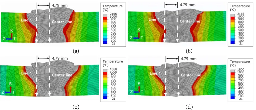
To identify the cause of these differences, the maximum temperature experienced by each node during the heat transfer analysis were compared. Figure 3 shows that the fusion area (1345 oC or higher) of the temperature method is wider than that of the heat flux method, even though the maximum temperature per pass calculated at specific points (TC 1 and TC 6) was matched. In the case of the temperature method, the nodes on the center line of the weld are melted at a temperature higher than the melting point and stress relaxation occurs due to the annealing effect, whereas the edge portion of the weld bead is not sufficiently melted in the case of the heat flux method. The difference in the fusion area appears to cause the difference in the residual stress distribution of two heat source input methods. However, in order to analyze the reason why the overall residual stress distribution tendency is similar despite the local differences, the area where the temperature exceeded 1000 oC during the weld simulation is shown in Fig. 4. All four FEA models show similar temperature distributions. It is likely that the influence of the temperature of the weld bead on the welding residual stress is low because the strength of the alloy 82 would be very low at such a high temperature. Therefore, the similar overall residual stress distribution was observed irrespective of the heat source input methods.
(a) (b)
(a) (b)
Figure 3. Comparison of fusion area; (a) FEA Model A(Flux-Birth) and (b) FEA Model C(Temp.-Birth) (Park et al., 2017).
(a) (b)
(c) (d)
Figure 4. Comparison of area over 1000 oC; (a) FEA Model A(Flux-Birth), (b) FEA Model B(Flux-Quiet), (c) FEA Model C(Temp.-Birth), and (d) FEA Model D(Temp.-Quiet) (Park et al., 2017).
Weld Bead Generation Methods
Figure 2 shows that the welding residual stress distributions are almost similar according to the weld bead generation methods. The vertical dotted line in Fig. 2 indicates the initial thickness of the welded part (about 12.77 mm), and the thickness after the weld simulation increased for all four FEA models (A to D). This increase in thickness should be the result of deformation and bending in the local welds due to thermal expansion and contraction during the welding simulation process. However, the element birth method shows a slightly larger increase in the thickness than the quiet element method. It is considered that the element birth method causes the element elongation and overlap, resulting in a thicker result than the actual thickness.
(a) (b)
(c) (d)
Figure 5. Residual stress contour; (a) FEA Model A(Flux-Birth), (b) FEA Model B(Flux-Quiet), (c) FEA Model C(Temp.-Birth), and (d) FEA Model D(Temp.-Quiet) (Park et al., 2017).
Analysis vs. Measurements
In order to confirm the validity of the weld residual stress analysis, the finite element analysis values along the Line 1 and the center line of the weld, as shown in Figs. 3 and 4, were compared with the measured values reported in MRP-316. Figures 6 (a) and (b) compare the results of the residual stresses along the center line and Line 1, respectively. For the case of the center line, the difference near the center of thickness is somewhat noticeable, but the difference tends to become small as it deviates from the center. For the case of Line 1, which is off the center line, the overall trends appear similar.
However, as shown in Fig. 6 (b), the welding residual stress drastically changes in the range of 3 to 6 mm from the outer diameter. In actual welding, it is expected that the weld material and the base material will melt together at the boundary and show a gradual physical property change. However, unlike actual welding, in the case of the finite element analysis model, sudden changes in the physical properties occur at the boundary between the weld material and the base material, which appears to cause the sudden stress change in this specific section.
(a) (b)
CONCLUSION
In this paper, the effects of heat source input and weld bead generation methods on finite element analysis of cylindrical multi-pass metal welds were investigated. The main results are as follows. Two heat input methods were considered: the heat flux method and the temperature boundary condition method. Although results of thermal analysis between two heat input methods were slightly different, distributions of the residual stress were similar. Because the areas exposed to high temperature were similar and the strength of the material was very low in high temperature (above the 1000 oC), the effects of the weld bead temperature were insignificant. Two weld bead generation methods were also considered: the element birth method and the quiet element method. The distribution of the residual stress was similar to each other. However, gaps and overlaps occurred on the welding boundary surfaces as the element birth method was applied. The quiet element method is more suitable for a large deformation model in order to simulate a more accurate weld shape. The analysis results of the residual stress showed an overall similar tendency to the measured values at the weld center line and off-the-center line.
ACKNOWLEDGEMENT
This work was supported by “the Nuclear Safety Research Program through the Korea Foundation of Nuclear Safety (KOFONS) granted financial resource from the Nuclear Safety and Security Commission (NSSC), Republic of Korea (No. 1403006), and was supported by “Human Resources Program in Energy Technology” of the Korea Institute of Energy Technology Evaluation and Planning (KETEP), who granted the financial resources from the Ministry of Trade, Industry & Energy, Korea. (No. 20164010201000).
REFERENCES
Bae, H-Y., Kim, J. H., Kim, Y. J., Oh, C. Y., Kim, J. S., Lee, S. H. and Lee, K. S. (2012). "Sensitivity analysis of finite element parameters for estimating residual stress of J-groove weld in RPV CRDM penetration nozzle," Trans. Korean Soc. Mech. Eng. A, Vol. 36, No. 10, pp. 1115~1130.
Benson, M., Rudland, D. J., and Csontos, A. (2014). “Weld Residual Stress Finite Element Analysis Validation: Part 1, Data Development Effort," US Nuclear Regulatory Commission, Washington, DC., NUREG-2162.
Brickstad, B. and Josefson, B.L. (2008) "A parametric study of residual stresses in multi-pass butt-welded stainless steel pipes," International Journal of Pressure Vessels and Piping, Vol. 75, pp. 11~25. Broussard, J. (2015a). "Materials Reliability Program: Finite-Element Model Validation for Dissimilar
Metal Butt-Welds (MRP-316, Revision 1)," Vol 1 and 2, EPRI, Palo Alto, CA.
Broussard, J. (2015b). “Material Reliability program: welding residual stress dissimilar Metal butt-weld finite element modeling handbook (MRP-317, Revision 1),” EPRI, Palo Alto, CA.
Dassault Systems (2015). "ABAQUS 2016 User’s Manuals."
Elcoate, C.D., Dennis, R.J., Bouchard, P.J., Smith, M.C. (2015) "Three dimensional multi-pass repair weld simulations," International Journal of Pressure Vessels and Piping, Vol. 82, No. 4, pp. 244~257.
Goldak, J., Chakravarti, A., and Bibby, M. (1984) "A new finite element model for welding heat sources,"
Metallurgical transactions B, Vol. 15, No. 2, pp. 299~305.
Kim, J-S., Ra, M.-S., and Lee, K-S. (2015) "Investigation on the effects of geometric variables on the residual stresses and PWSCC growth in the RPV BMI penetration nozzles," Journal of Mechanical Science and Technology, Vol. 29, No. 3, pp. 1049-1064.
Lindgren, L.-E. (2001) "Finite element modeling and simulation of welding part 1: Increased complexity," Journal of thermal stresses, Vol. 24, No. 2, pp. 141~192.
Park, W. D., Bahn, C.B., Kim, J.H. (2017). “Effects of Heat Input and Bead Generation Methods on Finite Element Analysis of Cylindrical Multi-Pass Welding Process of Metals,” Trans. Korean Soc. Mech. Eng. A, Republic of Korea, to be published on June 2017.
Rudland, D., et al, (2007) "Comparison of welding residual stress solutions for control rod drive mechanism nozzles," ASME 2007 Pressure Vessels and Piping Conference, American Society of Mechanical Engineers, pp. 997~1011.
Song, T.-K., Bae, H.-Y., Kim, Y.-J., Lee, K-S. and Park, C-Y. (2008). "Sensitivity analyses of finite element method for estimating residual stress of dissimilar metal multi-pass weldment in Nuclear power plant," Trans. Korean Soc. Mech. Eng. A, Vol. 32, No. 9, pp. 770~781.
Song, T.-K., Bae, H.-Y., Kim, Y.-J., Lee, K-S., Park, C-Y., Yang, J-S., Huh, N-S., Kim, J-W., Park, J-S., Song, M-S., Lee, S-G, Kim, J-S, Yu, S.-C. and Chang, Y-S. (2009). "Assessment of round robin analyses results on welding residual stress prediction in a nuclear power plant nozzle," Trans. Korean Soc. Mech. Eng. A, Vol. 33, No. 1, pp. 72~81.
Yaghi, A., Hyde, T.H., Becker, A.A., Sun, W. and Williams, J.A. (2006) "Residual stress simulation in thin and thick-walled stainless steel pipe welds including pipe diameter effects," International Journal of Pressure Vessels and Piping, Vol. 83, No .11, pp. 864~874.
Yaghi, A.H., Hyde, T.H., Becker, A.A., and Sun, W. (2013) "Finite element simulation of residual stresses induced by the dissimilar welding of a P92 steel pipe with weld metal IN625,"