ROBOTIC ENDOSCOPE
Jon K Edwards
A dissertation submitted to the faculty of the University of North Carolina at Chapel
Hill in partial fulfillment of the requirements for the degree of Doctor of Philosophy in
the Department of Biomedical Engineering at the School of Medicine.
Chapel Hill
2012
Approved By:
Robert Dennis, PhD
Nancy Allbritton, MD, PhD
Mark Tommerdahl, PhD
Jeffrey MacDonald, PhD
Shawn Gomez, PhD
ii
©2012
Jon K Edwards
ALL RIGHTS RESERVED
iii
Abstract
JON K EDWARDS: Robotic Endoscope Under the Direction of Dr. Robert Dennis
The endoscope has become ubiquitous and indispensable, changing many surgical procedures from life-threatening to outpatient. Use of the endoscope is limited by the ability to safely navigate circuitous paths, provide a stable tip in situ, and generate force where and as needed. Our lab developed a prototype robotic endoscope which mitigates these limits and is able both to contort to follow a convolved path and to generate tip-force in any direction. This design can be mounted at the extracorporeal end of any control system, extending existing surgical robots’ utility. The effectors’ actuators (stepper motors in this prototype) are external to the effector and transmit force via cables (aka tendons), and, assuming nonferromagnetic robot-segment composition, the design is safe for use with MRI and X-ray. A hollow core allows for in situ tool exchange, and hollow wall channels allows for routing permanent tools to the effector tip (e.g., vacuum, saline, fiber optics).
iv
v
Acknowledgements
The author would like to thank Dr. Bob Dennis for his time, insight, and apt assistance, my committee for their generous and patient guidance, and Steven Emanuel for his help
vi
Preface
I had atrial fibrillation surgery twice. The first time killed me, but I got better. Surgery entailed going between two ribs, pushing the lung aside, and burning arcs across the surface of my heart in hopes of interrupting ectopic pathways. My heart stopped and was restarted. They sewed me up, and then reopened me when internal hemorrhaging wouldn’t stop. After a week in intensive care and several months as a semi-invalid, I was unimpressed.
The second surgery was endoscopic, took most of a day to perform and a day to recover from. The endoscope itself looked crude but performed perfectly. The surgery worked. I was inspired.
The goal to designing this prototypic endoscope was to develop a tool which would overcome the perceived shortcomings of existing designs. I wanted the endoscope to be able to navigate circuitous paths without using interstitial tissue to redirect the endoscope, to be able to generate force omnidirectionally at the tip and orthogonally along the shaft, to improve the surgeon’s toolset.
vii
Table of Contents
List of Tables ... xiii
List of Figures ... xiv
Terminology ... xix
Chapter 1: Background ... 1
Chapter 2: History and State of the Art ... 4
Chapter 3: Methods to Design the Snakebot ... 6
Actuators ... 7
Tensegrity ... 7
Stacked Segments ... 8
Segment Naming Paradigm ... 9
Abandoned Designs ... 9
Asymmetrical Segment ... 9
Symmetric Segment with Offset Bearings ... 10
Asymmetric Segments with Centered Bearings ... 10
Symmetric Segment with Orthogonal Cams ... 11
viii
Version 1 - Flat Faced Cam ... 11
Version 4 - Hemicylindrical Cams ... 12
Version 5 - Y-Shaped Control Cable Via ... 13
Version 6 - Surface Control Cable Vias ... 14
Version 7 - Construction Cables ... 15
Version 10 - Lidded Control Cable Via ... 16
Version 11 -Thicker Segment Walls ... 17
Version 12 – Enlarged Control-Cable Via ... 18
Segment Dimension Solution-Space ... 21
Cam Radius ... 21
Cam-Shoulder Angle ... 22
Segment Length ... 23
Segment Diameter ... 23
Segment Evolution Results ... 24
Known Segment Issues, Solutions, and Improvements ... 26
Control Cable Tension Hysteresis ... 26
Segment Wall Thickness ... 26
Tapered Y-Channel ... 27
Manually Manipulated Snakebot ... 28
Motorized Snakebot ... 29
ix
Force Sensor Blocks ... 31
Stepper Motors ... 32
Stepper Controller ... 33
Arduino 328p ... 33
Arduino Motor Shield ... 35
Motor Shield Adaptation ... 36
Arduino 2560 microcontroller ... 38
Joysticks ... 38
Stepper Power Supply ... 40
The Sled ... 41 Computer Hardware ... 45 Power Relay ... 45 Communications ... 46 USB ... 46 TWI ... 46
Mushroom Slap Switch ... 47
2560 Status LEDs ... 48
Software... 49
Source Code Overview ... 49
USB Interface ... 50
x
parseMoveCommand ... 52
parseLEDcommand ... 52
parseEEPROMdataReq ... 53
PC-to-328 Command Set ... 54
Overview ... 54
joystickEE Command ... 54
Chapter 4: Testing the Snakebot ... 55
Zeroing the Snakebot Steppers ... 55
Zero Sled Position ... 55
External Bracing to Zero Snakebot Segments ... 56
Maze-Table Fixture ... 56
Zeroing Snakebot Axes ... 57
Results of External Bracing ... 57
Internal Bracing to Zero Snakebot Segments ... 58
Results of Internal Bracing ... 58
The Maze ... 59
Maze-Test Results ... 61
Chapter 5: Results of Snakebot Design ... 62
Chapter 6: Future Development ... 64
Pair of Coordinated Snakebots: The Caduceus ... 64
xi
Intelligent Path Planning, Kinematics, Control ... 65
Inflatable Collar ... 65
Materials Choices for Small-Diameter Endoscope ... 66
Snakebot-Tip Vision ... 66
Miscellaneous Improvements ... 66
Chapter 7: Conclusions ... 67
Appendix 1: Robotic Segment-Shape Solution-Space ... 68
Appendix 2: Software ... 127
Embedded Code for the 2560 ... 127
Snakebot_2560.c: ... 127 Snakebot_2560.h ... 137 Menu2560.c ... 140 Menu_2560.h ... 151 Led_2560.c ... 152 LED_2560.h ... 162 Snakebot_EEPROM2560.c ... 164 Snakebot_EEPROM2560.h ... 195 Version.h ... 199
Embedded C for the 328p ... 201
Snakebot_328p.c ... 201
xii
AFMotor.cpp ... 239
Embedded C common to both 2560 and 328p ... 253
Snakebot_common.c ... 253
Snakebot_common.h ... 276
Software from Arduino Library ... 282
HardwareSerial.cpp ... 282 Twi.c ... 295 Wire.cpp ... 314 Pins_arduino.c ... 325 Print.cpp ... 343 Wiring_digital.c ... 352
DOS Batch file to program 328p array... 359
xiii
List of Tables
Table 1 - Snakebot Segment Naming Paradigm ... 9
Table 2 - Segment Parameters ... 25
Table 3 – Adaptation of Motor Shield ... 36
Table 4 - PC to 2560 Command Set ... 51
Table 5 - PC to 2560 Move Command Parameters ... 52
Table 6 - PC to 2560 LED control commands ... 52
Table 7 - PC to 2560 - EEPROM access command set ... 53
Table 8 - PC-to-328p Command Set ... 54
xiv
List of Figures
Figure 1 - Tensegrity Structure... 7
Figure 2 - Wooden Prototype of Stacked Segments ... 8
Figure 3 - OAS1H1FN - asymmetric cam assembly ... 9
Figure 4 - OSS4H1RN – ... 10
Figure 5 - CB1H2RN - Asymmetric Segments with Centered Bearing - Female ... 10
Figure 6 - CC1H2RN - Asymmetric Segments with Centered Bearing - Male ... 10
Figure 7 - CS1H2RN – Symmetric ... 11
Figure 8- Segment CS2H2FN Assembly ... 11
Figure 9 - Version 4 – ... 12 Figure 10 - Version 5 ... 13 Figure 11 - Version 6 ... 14 Figure 12 - Version 7 ... 15 Figure 13 - Version 10 ... 16 Figure 14 - Version 11 ... 17
Figure 15 - Version 12 Assembly ... 18
Figure 16 - Version 12 - Control Cable Routing ... 19
Figure 17 - Version 12 - Structural Cable Routing ... 20
Figure 18 - Varying Cam Radius (Shoulders at 45-degrees)... 21
Figure 19 - Cam Shoulder Angles ... 23
Figure 20 - Segment 11 Snakebot – nonmotorized ... 28
Figure 21 - Baseplate with Motors, Force Sensor Blocks, and Snakebot Base ... 30
Figure 22 - Force Sensor Sliding Block ... 31
xv
Figure 24 - Force Sensor Blocks on Baseplate ... 32
Figure 25 - Stepper Motor ... 32
Figure 26 - Motorized Snakebot (without sled) ... 33
Figure 27 - Arduino 328p Microcontroller ... 34
Figure 28 - Arduino 328p schematic ... 34
Figure 29 - Motor Shield ... 35
Figure 30 - Motor Shield Schematic ... 35
Figure 31 - Motor Shield Adaptation - Custom IC Socket ... 37
Figure 32 - Schematic of Motor Shield Adaptation ... 37
Figure 33 - - Arduino 2560 microcontroller ... 38
Figure 34 - Joysticks Controlling Eight Snakebot Axes... 39
Figure 35 - Sled Joystick ... 39
Figure 36 - Power Supply for Stepper Motors ... 40
Figure 37 - Relay controlling power supply ... 40
Figure 38 - Snakebot Sled and Frame ... 41
Figure 39 - Snakebot mounted on Sled ... 42
Figure 40 - Ganged Steppers to Drag Sled ... 42
Figure 41 - Sled Pulleys ... 43
Figure 42 - Axis Controlling Stepper's ... 43
Figure 43 - Computer Hardware Topology ... 45
Figure 44 - Stepper Motor Interrupter Slap Switch ... 47
Figure 45 - LEDs controlled by 2560 ... 48
Figure 46 - Sled Zeroing ... 55
Figure 47 - Fixture to positon Maze-Table relative to Snakebot Sled ... 56
Figure 48 - Fixture to Zero Table, Sled, Snakebot – External Bracing ... 57
xvi
Figure 50 - Fixture to Zero Table, Sled, Snakebot – Internal Bracing ... 58
Figure 51 - The Maze ... 59
Figure 52 - Maze in position on Table with Snakebot at Zero ... 59
Figure 53 – Snakebot Zeroed at End of Maze ... 60
Figure 54 – Snakebot Midway through Maze ... 60
Figure 55 – Snakebot at End of Maze ... 60
Figure 56 - Snakebot at End of Maze (closeup) ... 61
Figure 57 - Snakebot in End-of-Maze Configuration without Maze ... 61
Figure 58 - Snakebot Balloon Collar ... 65
Figure 59 - Tensegrity Prototype ... 68
Figure 60 - First Prototype Using Segments ... 69
Figure 61 - Segment Design CSS1H1PN1CW90 ... 70
Figure 62 –Segment Design CSS1PN1CW90 ... 71
Figure 63 - Segment Design CS2H2FN ... 72
Figure 64 - Segment CS2H2FN Assembly ... 73
Figure 65 - Segment Design CC1H2RN ... 74
Figure 66 - Segment Design CBC2H2FN ... 75
Figure 67 - Segment Design CB1H2RN ... 76
Figure 68 - Segment Design CS1H2RN ... 77
Figure 69 - Segment CS1H2RN Assembly ... 78
Figure 70 - Segment Design CB1H1PN ... 79
Figure 71 - Segment Design CS1H1PN ... 80
Figure 72 - Segment Design CC1H2PN ... 81
Figure 73 - Segment Design CB1H2PN ... 82
Figure 74 - Segment Design CS1H2PN ... 83
xvii
Figure 76 - Segment Design 2BV2 ... 85
Figure 77- Segment OSS1H1PN1CS90 Assembly 2 ... 86
Figure 78 - Segment Design OSB4H1RN1CW90 ... 87
Figure 79 - Segment Design OSS4H1RN1CW90 ... 88
Figure 80 - Segment OSS4H1RNCW90 Assembly ... 89
Figure 81 - Segment Design OSB2H1RN1CW90 ... 90
Figure 82 - Segment Design OSC1H1PN1CW90 ... 91
Figure 83 - Segment Design OSB1H1PN1CW90 ... 92
Figure 84 - Segment Design OSS1H2PN1CW90 ... 93
Figure 85 - Segment Design OSB1H2PN1CW90 ... 94
Figure 86 - Segment Design OSC1H2PN1CW90 ... 95
Figure 87 - Segment OSS1H2RN1CW90 Assembly ... 96
Figure 88 - Segment Design OSS1H1PN ... 97
Figure 89 - Segment OAS1H1PN1CW90 Assembly ... 98
Figure 90 - Segment Design OAB1H1FN ... 99
Figure 91 - Segment Design OAC1H1FN1 ... 100
Figure 92 - Segment Design OAS1H1FN1CW90 ... 101
Figure 93 - Segment OAS1H1FN1CW90 Assembly ... 102
Figure 94 - Segment Design OAS1H1PN ... 103
Figure 95 - Segment Design OAS1H1PN ... 104
Figure 96 - Segment OAS1H1PN Assembly ... 105
Figure 97 - Segment Design OAS1H1PN ... 106
Figure 98 - Segment Design OAC1H1PN ... 107
Figure 99 - Segment Design OAB1H1PN ... 108
Figure 100 - Version 3 Segments ... 109
xviii
Figure 102 - Version 5 Segments ... 111
Figure 103 - Version 6 Segments ... 112
Figure 104 - Version 7 Segments ... 113
Figure 105 - Version 9 Segments ... 114
Figure 106 - Version 9 Assembly ... 114
Figure 107 - Version 10 Segment ... 115
Figure 108 - Version 10 Assembly ... 115
Figure 109 - Version 11 ... 116
Figure 110 - Version 12a ... 117
Figure 111 - Version 12a Assembly ... 118
Figure 112 - Version 12a with stabilization balloon-collar ... 119
Figure 113 - Baseplate for Version 12a - nonmotorized snakebot ... 120
Figure 114 - Baseplate for Segment Version 12a - motorized snakebot ... 120
Figure 115 - Implementation of OSS4H1RN1CW90 ... 121
Figure 116 - Implementation of CS1H2PN ... 122
Figure 117 - Implementation of CSS1PN1CW90 ... 123
Figure 118 - Implementation of CS2H2FN ... 123
Figure 119 - Scrapbot - versions 3 through 10 ... 124
Figure 120 - Segment 11 Snakebot - nonmotorized ... 125
xix
Terminology
2560 – Arduino 2560 is a Microcontroller, also known as a microcomputer, SBC (single board computer) or
Embedded controller. Arduino is a manufacturer
328p – Arduino 328p is a less powerful version of the 2560
Daughter board - an extension of the motherboard by pins and sockets
Motor shield –
A ‘daughter board’ that plugs into the sockets along the edges of the Arduino 328p and is controlled by TTL signals from the 328p.
The output of this board is stepper-motor control or a variety of DC motor applications, depending
on how the 328p is programmed Flash – type of nonvolatile memory
Faster than EEPROM, slower than RAM EEPROM – electrically erasable
programmable read-only memory. This is nonvolatile
much slower than RAM; provides a means to store nonvolatile data (eg, operating system configuration data, or, in the case of the snakebot, axes’ configurations for
xx
computer memory ‘claymation’ motion)
USB – Universal Serial Bus a serial communications protocol
USB hub – a tool for the distribution of USB signals. One input is distributed to many outputs. Responding signals from any of the ‘output’ plugs are routed to the ‘input’ plug. Functionally this is a multiplexer (mux).
I2C – Inter Integrated Circuit also known as TWI (two wire Interface) is a low-speed communication protocol TTL – transistor to transistor logic
A logic false is represented by 0VDC, a true by +5VDC DC – direct current
AC – alternating current
Claymation – a form of stop-motion animation: objects (eg a snakebot) are moved
incrementally, then the
configuration ‘frozen’ (eg, with a camera or by writing
configuration data to memory)
IC – integrated circuit
IC socket – a device for physically holding an IC on a circuit board and electrically connecting the IC to the circuit
xxi CAD – computer aided design
Use of computer software to simulate an object before it is physically produced in hopes of an efficient and correct design process
Cables – aka tendons, strings, wires
ASCII - American Standard Code for Information Interchange
A protocol for digitally encoding alphanumeric data
A/D – analog to digital converter A tool for approximating analog inputs for digital processing
Stepper motor – a DC controlled motor where the shaft position is controlled by changing applied DC voltage. Since the shaft moves in discrete increments, no encoder is necessary to know shaft radial position
Stacking Header – this
computer-board hardware allows the electrical and physical connection of two printed-circuit-boards. Once soldered to the first board, the pins are pressed into the female socket of a similar header.
xxii PVC - Poly Vinyl Chloride.
a type of plastic from which plumbing pipes are commonly fabricated
LESS – Laporoendoscopic Single-Site Surgery –
endoscopic surgery performed using a single perforation in the patient’s body.
Lumen – the inside space of a structure
Cannula – latin for ‘little reed’, a hollow tube for introducing foreign material to the body, taking samples, or creating a portal through which to access internal material
Chapter 1
Background
Endoscope design is an intersection of many disciplines, including robot design,
computer science, material science, human-machine interface (HID), all joining to meet the need of safely navigating the patient’s body and performing the task the surgeon requires once in position. Whether surgical access is through existing orifices, as with NOTES, or by small incisions, as with LESS and MIS and RSP (1; 2), the goal is to provide the surgeon a stable platform within the patient from which to cut, sew, and grasp, all while clearly imaging patient tissues. This design is for that portion of the tool between the extracorporeal positioning structures (robot arms) and the end-effector (gripper, scalpel, saline, suction, etc.) and can be adapted to any hierarchal positioning mechanism; issues of extracorporeal routing of the structures supporting this effector around the patient’s body and whether the robot is to be the surgeon’s slave or collaborator are not addressed here.
Endoscopes allow the surgeon to navigate parts of the circulatory system and much of the body, performing many surgeries more quickly, safely, and with better outcome than traditional methods. Too flexible an endoscope cannot offer sufficient stability to perform cutting and grasping, while too stiff an endoscope cannot navigate safely (3; 4). Some flexible endoscopes navigate by curling the tip of the scope and twisting the base to orient towards the goal, then pushing the scope forward. This works as long as the forward force at the base is redirected along the shaft of the endoscope by the tissue of the patient towards the desired target, but can damage the patient if the route requires too sharp a turn or impinges delicate tissues. Other
2
designs incorporate multiple controllable segments (continuum manipulator endoscopes), but still rely on interstitial tissue to redirect force to the tip (5).
Our prototype design is derived from a cannula (6), generating force and motion at the tip without requiring force against interstitial tissue. Inspiration for the design came from study of a human hand (7), which also utilizes remote actuators (muscles). Force at the snakebot tip is transferred to the base through robot-segment compression and cable tension. The snakebot can use interstitial tissue to push off against, just as is done with conventional endoscope navigation, or it can conform to lumen and create minimal tissue stress. With the former paradigm, the tip flex is reduced and tip-force application is made more deterministic.
This snakebot endoscope is a delivery system for surgeons’ tools, with a hollow core through which scalpels, grippers, or cameras can be exchanged in situ. The robot segments’ wall thickness contains channels or vias which can facilitate routing in the walls of fiber optics for illumination and endoscopic-tip-vision (8), delivery of saline, and vacuum lines, all without compromising surgical-implement-payload. This concept of a snakebot is neither new nor unique, being but a series of universal joints, but this design improves on previous
implementations by maintaining a lumen though which tools can be interchanged and from its use of cabling to replace hinges and pivots. (9; 10; 11; 12)
The snakebot can self-propel through the patient’s body, producing motive force not just from the endoscope base being manipulated but by serpentine motion of the snakebot’s body. Clearly it can be dangerous to have a tool forcing itself through a patient and perhaps perforating an organ, so the robot is equipped with force sensors and would proceed under the surgeon’s direct control. Path planning becomes nontrivial as both modes of propulsion (serpentine and base-generated) must consider potential interstitial damage.
Snakelike robot designs vary widely (13), ranging from climbing robots (14) to serpentine rolling robots (15) to inspection robots (16) to ‘elephant trunks (17)’. Actuator type and placement vary as well, from external pneumatics (18; 19) to internal (to the snakebot) motor
3
or memory metal (20). The design described here is a puppet, controlled by cables (tendons) attached to robot segments at one end and to a stepper motor at the other. The advantages are the motors’ ferromagnetic parts are as remote as is necessary to allow the effector to be used in MRI or Xray machinery, and the effector can be as small as necessary to do the surgery and still generate significant force at the tip.
Chapter 2
History and State of the Art
Endoscope history is over four millennia long, with Egyptian an papyrus referring to endoscope use in 2460BCE (21). Modern endoscope history begins in 1806 with Bozzini’s lichleiter or ‘Light Conductor’ (22). The first internal lights were used by Charles David in 1908. Endoscopes were used to diagnose liver and gallbladder disease by Hienz Kalk in the 1930’s and by Raoul Palmer in 1944 to perform gynecologic surgery. Commercial flexible gastroscopes were available in 1911 and semi-flexible gastroscopes in 1930, but real progress in endoscope use and design began when, in 1960, Storz marketed a ‘cold light’, an extracorporeal light source that routed illumination without heat into the body.
In combination with the medical optics of Harold Hopkins, the endoscope became a viable tool. A camera at the gastroscope tip was developed in 1950 by Sugiura and was used to diagnose stomach ulcers. Fiber optics were introduced in the 1950’s by Hopkins but were unreliable and low-resolution until Hopkins and Storz optimized the optics, an evolution that enabled modern key-hole surgeries and earned Hopkins the Rumford Medal in 1984.
Endoscope use changed with the inclusion of robotics, which never tire, do not tremble, and can report applied forces accurately. The level of automation integration varies with
platform, from a generic holder attached to the same endoscope a human would use (23) to highly integrated master-slave systems where the surgeon interfaces a remote display and may not even be in the same city as the patient (24).
5
The design of hyper-redundant robots and their close relative, the continuum robot, also has a long history. Implementation of a ‘Tensor Arm Manipulator’ was developed by Anderson in 1967 (25; 26), which demonstrated the utility of hyper-redundant puppet robot design.
Continuum robots share the tendon-actuation with this design, but rely on a flexible core for force redirection and, having fewer cables, are not as inherently compliant (27).
Current research is focused on developing capsule endoscopes, surgeon-interface refinements, and types of extracorporeal robot positioning systems. The design of the portion of the endoscope actually in situ varies from rigid to flexible (28), and of varying degrees of automation, depending on the system and application. Designs similar to this prototype are also being developed (29; 30), but none combines the simplicity of segment design with the
Chapter 3
Methods to Design the Snakebot
This prototype snakebot was developed using a top-down approach of ‘what should the tool accomplish’ and iterated across the potential solution-space to refine the design. Design criteria included .
1. maximize the ‘payload’ of the snakebot (the lumen of the snakebot through which tools might be inserted with the snakebot in situ)
2. provide a stable platform for tip-manipulation of payload-borne tools (scalpels, grippers, optics, etc.)
3. be able to generate tip-force omnidirectionally and deterministically 4. be strong enough to sustain the rigors of surgery
5. be flexible enough to navigate three-dimensional curved paths
6. be small enough to minimize unnecessary incidental damage incurred by navigating the patient’s body
7. be fabricated from non ferromagnetic material so can be used in an MRI The design effort was intended to produce the snakebot actuator, that part of an endoscopic system between the endoscope’s extracorporeal (to the patient) positioning system and the tools at the tip. Demonstration of the capability of the snakebot required design of ancillary systems, including force sensors, actuators, and a rudimentary extracorporeal positioning system.
7
Actuators
Various actuators were considered, including stepper motors, DC motors, memory metal, artificial muscles, and inflatable muscles. Actuators integral to the snakebot’s body were deemed impractical for three reasons:
1. a motor small enough to fit within a narrow endoscope would be too weak to be useful. 2. if a motor strong enough to meet the needs of a snakebot existed it would require wiring
for power, control, and encoder data, wiring which would require at least as much of the endoscope’s volume as would tendons.
3. Any ferromagnetic content would render the endoscope incapable of working in an MRI, a feature which cable actuation preserved by removing motors from the endoscope body. These premises made clear the design would incorporate tendons (a.k.a. cables or strings) to transfer force from a motor to the segment. Low cost and ease-of-implementation refined the actuator choice to stepper motors.
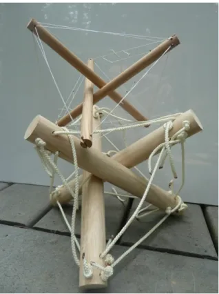
Tensegrity
Drawing inspiration from Buckminster Fuller, the first attempt used tensegrity
structures to construct a robust controllable endoscope.
While this design might be made to work and would be strong, deterministic, and flexible, it would be difficult to implement kinematics and controls. For example, to bend the tensegrity would require simultaneous
8
adjustment of all twelve cables per segment. Furthermore, such a design would have protruding edges which would inevitably catch on interstitial tissues. This approach was abandoned.
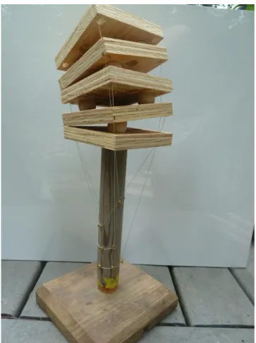
Stacked Segments
The following figure shows a first gesture towards narrowing the range of potential designs and showing the utility of cables-as-controls. This plywood-and-wood-ball prototype shows the alternating orthogonal cams
and pivoting platforms which will be implemented in the final prototype. The routing of cables through common vias and the use of a single cable per platform (routed from platform edge to the base and back to the opposite edge of the same platform) is also a feature of the final prototype.
Experimenting with this prototype demonstrated how moving proximal segment (one closer to the base) would change the orientation of all distal segments which share that degree-of-freedom (ie, all segments
which have their pivots on the same plane). This issue becomes more urgent as more segments are added.
9
Segment Naming Paradigm
Segment designs are named to describe the features permuted for that particular instance. Permutation parameters include placement of holes for routing of cables (a.k.a. ‘vias’), symmetry of the segment, cam placement, and pivot surface type. These parameters are described by single letters and appear in a consistent order to make parsing the name simple, as shown in the
following table.
1st – Cam
2nd - Shape 3rd - Type 4th 5th - Cable Route 6th - Point Type o – offset s – symmetric c – cap Iteration # H1 – holes at points Pn – unrounded c – centered a - asymmetric b – base H2 – holes offset 45 Pa – cut unrounded
s - segment Rn – hemicylinder
Fn - flattened Table 1 - Snakebot Segment Naming Paradigm
Abandoned Designs
Having established the general design of the endoscope as a sequence of stacked segments, an exploration of possible segment shapes ensued. There were thirty-seven permutations on the stacked-segment theme that were tried and abandoned for a variety of reasons. Segment aspects that were permuted include wall thickness, segment diameter, segment length, and a variety of shapes for the
interface between segments. The inventory of these permutations appears in the Appendix of Segment-Shape Solution Space, and a synopsis follows.
Asymmetrical Segment
The first permutation direction
10
abandoned was the nonsymmetric cam (eg the OAS1H1FN segment). These were envisioned to enable the snakebot to flex more in one direction than the other, so it might navigate particularly sharp corners. In practice, it required too much force to move an axis so designed and the transition from applying tension to motion too abrupt. Also, for such a segment pair to move, the cables to adjacent axes would have to both elongate, requiring two motors per segment and an unwieldy control paradigm.
Symmetric Segment with Offset Bearings
A variant on the asymmetric cam is a symmetric cam with asymmetric rotation faces. This had the same shortcomings of the
asymmetric cam.
Asymmetric Segments with Centered Bearings
Asymmetry had the clear problem of requiring complex control-cable manipulation of all segments from that which was being moved to the tip of the snakebot. It was not yet clear that this issue could be resolved only by routing the control cables through the axis of rotation between segments, so the next permutation attempted continued with the offset cable routing but attempted a symmetric bearing configuration.
Figure 5 - CB1H2RN - Asymmetric Segments with Centered Bearing - Female
Figure 6 - CC1H2RN - Asymmetric Segments with Centered Bearing - Male Figure 4 - OSS4H1RN –
11
Symmetric Segment with Orthogonal Cams
Having explored a variety of designs and found the asymmetrical paradigm infeasible, a line of symmetric orthogonal cams was designed.
Symmetric Segment with Small Cam
The next permutation line of inquiry abandoned involved forming a bearing surface between adjacent cams. For example,
segments CC1H2RN and CB1H2RN form a mating pair, and multiple-segment
CS1H2RN forms a segment set. This approach worked but was difficult to control. The small bearing surface between segments created a high-friction point such that the transition from statically applied tension and segment motion
was jerky and nondeterministic, making incremental change impossible.
The next version of this design (and the end of the cumbersome labeling paradigm which preceded it) was labeled Version 1.
Version 1 - Flat Faced Cam
By increasing the cam size, the next evolution became segment CS2H2FN. This design worked better than all previous, and the flat surface between segments made axial alignment easy, but the transition from applied
cable-tension to motion was abrupt, which Figure 8- Version 1 - Segment CS2H2FN Assembly Figure 7 - CS1H2RN – Symmetric
12 presented a problem.
Version 4 - Hemicylindrical Cams
By rounding the flat section of adjacent cam-faces of a segment, a smooth transition across the entire range of motion
was achieved.
This implementation worked, but the control cable routing was problematic. If routed through the center of the face, the cables would limit cam-travel and, when adjacent cams were not axially aligned, caused tension in distal segments’ control
cables. The cable routing through the apex of the cam did keep adjacent segments aligned, an advantage worth retaining.
Note the segment design includes eight vias, four aligned with a cam apex and four offset from the cam apex by 45-degrees. If the control cables were routed through the vias’ 45-degrees offset from the cam apex, this removed the effect of keeping adjacent segments aligned, allowing segments to become misaligned and the snakebot to collapse.
Figure 9 - Version 4 – Orthogonal Hemicylindrical Cams
13
Version 5 - Y-Shaped Control Cable Via
The solution was to route the control cable through the cam apex through a via shaped to keep cable-length of distal segment’s control cables constant throughout the range of motion. The first attempt at this solution is
Version 5 of the orthogonal-cam line.
This design proved to be difficult to manufacture and prone to misalignment issues. The former problem is an artifact of the process used to produce segments, Force Deposition Modeling (FDM), which is the process of laying down
successive layers of thin lines of plastic in a matrix. To create the gap through which control cables route through the cam’s apex, a purportedly removable plastic was used to fill the gap to support the permanent plastic that was ‘printed’ around it. Removing the thin layer of
placeholder plastic proved a challenge.
The control cable via was designed with a ‘Y’ profile so the total cable length to distal segments remained constant when the segment was moved. This design was much better than that of Version 4, and the Y-profile-channel feature was kept in future designs, but there was still some cable-tension hysteresis between the configurations of vertically-aligned cams and
angularly-displaced cams.
Once assembled, a snakebot of these segments quickly misaligned: the shoulders of one segment’s Y-channel groove fit into the Y-channel of the adjacent segment, so a very slight axial displacement of one segment resulted in the snakebot collapsing. The design was envisioned with the control cables acting to keep adjacent segments aligned, but this did not work since the
14
Y-channel was designed for maximum control-cable bundle diameter. At the proximal end of the snakebot, with control cables for all segments running through the via, the system remained aligned, but at more distal segment axes, with fewer control cables present in the via, more off-axis motion was possible and the segments became misaligned. Before misaligning, however, the design did show the utility of routing cables through the cam apex and of a shaped via to keep constant the lengths of distal segments’ cables.
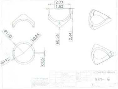
Version 6 - Surface Control Cable Vias
The next iteration of the orthogonal-cams line is Version 6, which routed control cables through surface vias
This design worked but not well. The design of the vias on alternating segment-faces was intended to create a ‘weave’ of the control cable surfaces such that the segments would be held in place in the snakebot while allowing adjacent segments to move. In practice, when adjacent segments were moved, the control cables tended to pop out of the via. Furthermore, there was enough
lateral motion between adjacent segments to allow these segments to become misaligned, allowing the snakebot to collapse.
To attempt to keep adjacent segments aligned, an additional set of cables was added. These construction cables were routed across the cam surface to act as hinges while keeping
15
adjacent segments correctly aligned. Grooves were created in the cam face to route the construction cables while keeping them from being damaged by the cam faces.
Version 7 - Construction Cables
The addition of the construction cable did help keep segments aligned, but was not a complete success: segments still came unaligned. Versions 7, 8, and 9 all explored permutations of construction cable via design in attempts to keep the segments aligned. All worked poorly since the construction cable tended to align with the stresses that occurred between segments rather than where the vias were inset to the segment, and adapting the via to follow the lines of force was iterative. In addition, the control cables tended to stay within the Y-channel vias as was designed, but would occasionally come out, particularly at high degrees of deflection of adjacent segments.
16
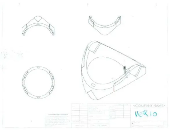
Version 10 - Lidded Control Cable Via
To keep the control cables in the vias, a ‘lid’ was added to Version 10. This lid kept the control cables in place, but the cam surface was too thin to keep adjacent segments aligned. One of the design criteria was to maximize the ‘payload’ of the snakebot, the lumen of the snakebot through which tools might be inserted in situ. Through Version 10, the payload was 90% of the snake’s cross section. Despite the addition of the construction cables, adjacent segments still became misaligned. To address this shortcoming, the wall thickness was increased in Version 11, which reduced the payload but resolved the misalignment problem.
17
Version 11 -Thicker Segment Walls
Figure 14 - Version 11
The cam surface was now thick enough to keep adjacent cams aligned throughout the range of travel of adjacent segments. The hollowing of segment walls was done initially to reduce material usage, but serendipitously these vias allow routing of permanent tools such as saline, vacuum lines, and fiber optic cables for lights and vision.
Production of these segments was problematic, however, due to the thin dimension of the control cable via. This narrow via also made assembly of the snakebot a challenge, an issue which, should this prototype ever be shrunk to production size, would become a serious obstacle.
18
Version 12 – Enlarged Control-Cable Via
Version 12 addressed the shortcomings of Version 11, combining the narrow control-cable-via with a material-saving via to create a larger channel. Also, fillets to via channel transitions were added to remove potential snag points.
19
20
21
Segment Dimension Solution-Space
Cam Radius
The radius of the segment’s cam determines how sharp a bend the snakebot can navigate. In the prototype, the radius of the hemicylindrical cam is less than the radius of the snakebot segment, but this dimension was arbitrary, a function of the process of exploring the segment-dimension solution space.
In the figure below, note that the configuration in which the radius of the cam is greater than that of the segment body becomes uncontrollable at angles where the cam faces are no longer in contact.
22
As the cam radius is increased, so must the control-cable via be lowered (for a given shoulder-angle), placing a physical limit on minimum segment length (ie, the segment has to be long enough to hold the control-cable via). In the case where the Cam Radius equals the Segment Radius, the control cable via is merely a radial hole through the segment body located at the center of the cam’s circle.
One problem with the configuration of the Cam-Radius equal to the Segment-Radius was the routing of the control cables at large angles-of-deflection: these cables crossed the payload space, either impacting and potentially crushing the payload or creating a cable-length-hysteresis wherein the total cable length varies with deflection-angle.
A smaller cam radius recreated the failures of segment CS1H2RN where the transition between applied tension and motion was difficult to control, making motions jerky. A larger cam radius increases the controllability and sensitivity of the snakebot.
Cam-Shoulder Angle
Another degree-of-freedom in the cam-dimension solution space is the angle of the cam ‘shoulders’, those flat surfaces adjoining the cam on segments where the radius of the cam is less than the radius of the segment body. Note it is this shoulder angle that determines the bend radius the snakebot can navigate, with larger shoulder angles generating snakebots that cannot navigate smaller-circumference paths.
23
Figure 19 - Cam Shoulder Angles
Segment Length
The minimum bend radius is proportional to the segment length. Increased segment length increased the lever-arm of each segment-joint, which increased cable tension per unit tip-force.
Segment Diameter
The prototype has a diameter of two inches. This was chosen because segments of smaller diameters are physically difficult to manufacture and assemble into a snakebot, and because the FDM material being used tended to break with smaller prototypes. When segment radius is increased, so does lateral stability and strength, but the minimum bend radius
24
Segment Evolution Results
The process of exploring the solution space was heuristic, evolutionary, and reactionary: permutations were proposed, simulated, produced, and improvements noted and used as the basis for the next iteration.
Snakebot dimensions can be customized for a given application, with a tradeoff of flexibility and complexity. Segments need not all be of identical dimension, so the tip can be composed of shorter, more dexterous segments while the body is composed of longer, more stable segments.
25 Cam radius R_cam > R_segment:
bad design.
Uncontrollable past angle_of_deflection > included_angle_of_ cam_surface. Also requires long control-cable vias
R_cam = R_segment: Good and bad: max snakebot
flexibility, but control cables cross payload-space at large angle-of-deflection
R_Cam < R_segment:
Good. Mandates use of ‘cam shoulder’, which controls min snakebot-navigable radius, which keeps control cables out of payload
Cam shoulder angle
Angle < 45-degrees: Good and bad: smaller minimum-radius-navigable, but control cables cross payload
Angle = 45-degrees: Good compromise: Control cables only impinge payload slightly, while snakebot can still navigate circle where R_circle >= (2.5 * R_segment) Angle > 45-degrees: Bad: payload is unimpinged, but snakebot loses navigability and cannot navigate sharp corners
Segment length
L_segment < R_segment:
Good and bad: many parts to create a long snakebot, with commensurate complexity to construction and controls, but very maneuverable. Optimal for tip of snakebot
L_segment = R_segment:
Good compromise. Perhaps optimal for mid-snakebot-body creation
L_segment > R_segment: Simplifies design effort for long snakebot, but less maneuverable. Optimal for base (distal segments) of snakebot. Wall thickness 90% payload: pre version 10
Bad for FDM snakebot prototype: segments cracked under pressure and would not stay axially aligned
50% payload: Version 10 and later: good. Stable. Perhaps excessive.
Less than 50% payload: excessive for FDM, but may be necessary with sintered TiCu alloy
Segment radius
1” – FDM prototype: smallest size that can be hand-assembled. Fragile when thin-walled. Too large for production endoscope
2” – FDM prototype: good for proof-of-concept. Features that would be too small for naked-eye-assembly are manageable at this scale >2” FDM: Unnecessary and wasteful
26
Known Segment Issues, Solutions, and Improvements
The last iteration, Version 12, is not quite optimal. It has control-cable tension hysteresis when moved from axially aligned to maximum deflection. The slack produced in the associated control cable (and all cables to distal segments that move in that degree-of-freedom) is small but enough to prevent deterministic kinematics, and the cumulative slack of multiple axes in the same degree-of-freedom all bent in the same direction (as when the snakebot curls in on itself) is not inconsiderable. Also, the wall thickness of Version 12 is excessive, a reaction to the inadequate wall-thickness of versions preceding it.
Despite the flaws of Version 12, it demonstrates the viability of a stacked segment design to generate tip-force omnidirectionally while the snakebot is contorted.
Control Cable Tension Hysteresis
The most pressing issue with Segment Version 12 is the cable-tension hysteresis. This problem manifests when the snakebot bends from axially aligned to a small-diameter curve: when aligned, all control cables are at maximum tension. As the snakebot bends, the control-cable path-length decreases due to the width of the ‘shielded via’ where it meets the ‘Y-shaped’ via.
The solution to this appears to be to curve the face of the ‘Y-channel’, increasing the total path length such that control cable tension remains constant over the range of segment motion.
Segment Wall Thickness
The second issue with Segment Version 12 is its payload. The current version has a segment diameter of 2”, with a payload of 1” diameter or 25% of the segment axial area. This provides a stable snakebot, but robs it of its purpose, which is to deliver usable payload space. Note that the transition from Version 10 to Version 11 increased the wall thickness from 0.15” to 1”, reducing the payload from 72.25% to 25%, which changed the snakebot from very unstable to
27
completely stable. The optimal design lies between these extremes, and will be a function of the snakebot diameter and material from which it is formed.
Tapered Y-Channel
The ‘Y-Channel’ of segment Version 12 removes part of the cam surface area. This may not be necessary. If the Y-Channel depth (as measured from the segment’s center axis) were tapered from a maximum depth at the point where it joins the ‘Shielded via’ to zero at the cam surface, the utility of the via would be accomplished while maximizing the segment stability.
28
Manually Manipulated Snakebot
A manually manipulated version of the snakebot segment Version 11 was constructed.
Figure 20 - Segment 11 Snakebot – nonmotorized
This prototype was controlled by turning the spools at the snakebot’s base. Since each axis is controlled by one spool, one person could simultaneously manipulate at most two segments. This demonstrated the ability of the snakebot to contort and to generate tip-force omnidirectionally. It was not clear that this paradigm would work once motorized, nor could this prototype demonstrate serpentine motion.
29
Motorized Snakebot
To enable the snakebot to perform serpentine motion and demonstrate the utility of the design of segment Version 12, a motorized snakebot was designed.
Baseplate
Design parameters for the motorized snakebot included a rigid baseplate to hold the snakebot with a motor for each snakebot joint (segment intersection). The prototype has eight segments, four in each of the two degrees-of-freedom. The baseplate also holds eight force sensors to detect cable tension on the control-cable. This latter feature is described in a subsequent section.
The baseplate chosen was formed from 12”x8”x3/8” aluminum, chosen because that thickness would not flex under applied control-cable tension. The baseplate also acts as a heatsink for the stepper motors.
30
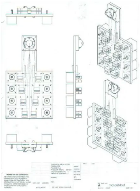
Figure 21 - Baseplate with Motors, Force Sensor Blocks, and Snakebot Base
The snakebot mounts at the end of the protruding arm, with the snakebot’s lowermost segment’s cam-face rotating against the cam-face of the hemicylindrical cam mounted to the baseplate. Both control and structural cables from the snakebot are routed to the baseplate: structural cables terminate at the baseplate, attaching the snakebot. Control cables route through the hemicylindrical cam attached to the baseplate, across the baseplate to the force sensor blocks, then to a stepper motor shaft.
31
Force Sensor Blocks
The prototype has a force sensor for each axis built into the baseplate. This sensor monitors the tension of the cable actuating that axis. There are several purposes to collecting this data. First, it is a way to generate axis limit data, since the limit-count of the stepper motor associated with a given axis changes as axes between that axis and the base move. Second, it offers the possibility of improved effector control and increased safety (31). Third, it offers the possibility of detection of interstitial tissue-type by ‘palpitation’; bone will offer little deflection per unit force, while soft tissues will offer more. Last, it offers the potential of active position maintenance, of having the steppers increase cable tension in response to applied force.
Figure 22 - Force Sensor Sliding Block Figure 23- Force Sensor Stationary Block
The force sensor consists of three pieces: a stationary block bolted to the baseplate, a sliding block held against the stationary part by the control cable tension across the rounded groove in the back of the sliding block, and a force sensor pad located between the two blocks.
32 Before the baseplate was mounted to the sled (described below), the force sensors were electrically connected to the 328p microcontrollers (also
described below). When the baseplate was mounted on the sled, the challenge of reconnecting the force
sensors was greater than the possible utility they might provide. On the sled-mounted
version of the snakebot, the sensors are in place, just not connected.
Stepper Motors
Steppers were chosen over alternatives because they are relatively inexpensive, powerful enough to move the snakebot, and able to move in discrete
increments and therefore do not require an encoder for their controller to ‘know’ their position. Alternative actuators considered include pneumatics, DC motors, and memory metal.
The requirement of strength and small size of the actuator inside the snakebot dictated the use of remote
actuation and cables. Low cost and the ability to use the stepper-count as an encoder further refined the option pool.
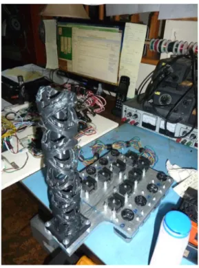
Note that in the figure “Motorized Snakebot (without sled)’, the steppers have attached to their shaft a wheel to which the control cables are glued. This increased the effective diameter of the shaft, causing the segments to move faster for a given stepper rotation. The wheel also affected the force that could be generated by the snakebot segments to such a degree that in some
Figure 24 - Force Sensor Blocks on Baseplate
33
configurations the steppers were unable to produce enough torque to move the snakebot and would ‘skip’. When the stepper
‘skipped’, its controller issued a move command and updated its internal count of the stepper’s position, but the stepper did not move. Later iterations of the motorized snakebot replaced the wheel with flexible tubing of smaller diameter, which reduced skipping by the stepper and added a slight flexion between forward and reverse actuation, reducing the cable-tension hysteresis problem.
Stepper Controller
Arduino 328p
To control the snakebot, steppers were chosen. To control the steppers, the Arudino 328p was chosen because, when combined with the associated ‘motor shield’ (described below), it offered the advantages of:
1. Inexpensive: an Arduino 328p with motor shield costs roughly $50 and will control two stepper motors.
2. Programmable: the Arduino development platform allows for programming in C, C++, and assembly.
3. Digital IO – the Arduino 328p has 23 digital Input/Output lines, of which 21 are used by the motor shield in controlling two stepper motors
4. Analog to Digital Conversion – the 328p has six analog inputs.
34
Figure 27 - Arduino 328p Microcontroller
35
Arduino Motor Shield
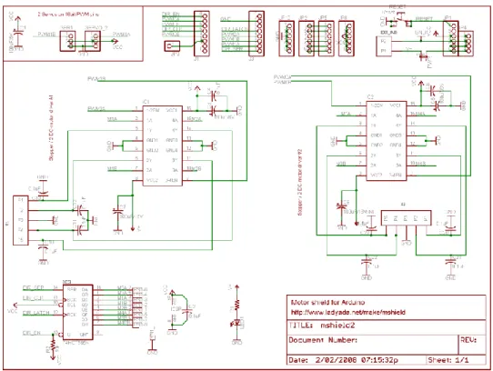
The Arduino ‘Motor Shield’ is a daughter board kit that, once assembled, mounts to the 328p via ‘stacking headers’. The motor shield is capable of controlling two stepper motors or four DC motors. It allows an external power supply to power the steppers instead of drawing power through the 328p, making possible the control of motors requiring higher voltages and currents.
Figure 29 - Motor Shield
36
The motor shield as it is designed has several shortcomings, primarily the lack of fuse in the stepper-power input and the capability to create short circuits within the multilayered printed circuit board. The former issue is addressed in the ‘sled’ version of the snakebot. The latter is a known bug with no resolution.
Motor Shield Adaptation
To implement the sled version of the snakebot requires the snakebot baseplate, five 328p controllers (four to control the snakebot and one to move the sled), a ‘sled’ to support the
baseplate and its controllers, and a stationary frame to support the sled. The moving portion is labeled the ‘sled’, and its weight is not inconsiderable. To move the sled, two steppers were used together. To ensure simultaneous movement of the two steppers, the motor controller attached to those steppers was adapted.
This adaptation consisted of disconnecting the lines from the motor shield’s 74HCT595N to IC2 (pins 5, 6, 7, and 15 of the 74HCT595N), then connecting the lines from 74HCT595N to IC1 to IC2. 74HCT595N Disconnect Reconnect 5 1 6 3 7 4 15 2
Table 3 – Adaptation of Motor Shield
This disconnection and reconnection was accomplished by rewiring a chip socket so that all the changes were confined to the chip socket: if the motor shield, the 328p, or the
37
Figure 31 - Motor Shield Adaptation - Custom IC Socket
The blue zip tie holds the IC Socket, the IC, and the heat sink. It is there to keep the stack compressed and so ensure positive electrical connection of the socket’s pins.
38
The effect of this alteration is that both ganged steppers are controlled by the signaling intended for IC1, ensuring simultaneous movement of both steppers. The fan-out on
74HCT595N was not exceeded, but a heat-sink was added to prevent that IC from overheating. Further documentation of the ganged steppers appears in the section on the snakebot’s sled.
Arduino 2560 microcontroller
Early in the process of software development of the motorized snakebot, the hierarchical control system consisted entirely
of a network of 328p microcontrollers. A bug manifested as an asynchronous reset of the central 328p. The memory map of allocatable RAM and ROM had been violated: the
stack was blown. There was insufficient RAM for the software application run on a 328p. The 2560 was selected to replace the central 328p. It used the same development environment, had the same TWI communications hardware as well as the same USB hardware, and supplied larger RAM and ROM. It also offered 16 analog-to-digital input lines, offering the capability to monitor all the force sensors currently in use.
Joysticks
Control of each axis is achieved through software. This can be implemented through several interfaces, including a joystick. Each joystick controls two orthogonal and sequential axes of the snakebot. Segment number zero is the one closest to the snakebot’s base.
39
Figure 34 - Joysticks Controlling Eight Snakebot Axes
Each joysticks consists of two variable resistors connected between 0VDC and +5VDC, generating a voltage between zero and five
volts proportional to the deflection of the joystick. This voltage is fed to the analog-to-digital converter of the 328p which controls the axes associated with the joystick.
The sled is also controlled by a joystick. Although both axes of the joystick are connected to the 328p’s A/D input, only one axis’ data is used since the sled has only one degree-of-freedom.
Although the snakebot can be controlled using joystick input, this is only marginally better than the manually manipulated snakebot described in the previous section. Subsequent software development built on the joystick input to implement ‘claymation’.
40
Stepper Power Supply
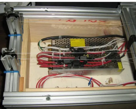
The stepper motors require more power than can be supplied through the 328p’s USB connection. To provide the correct voltage and sufficient current, a power supply is connected to each motor shield.
Figure 36 - Power Supply for Stepper Motors
Each line from the power supply has a fuse. The power supply converts 115VAC to +12VDC. The 115VAC is switched on/off by a relay, which is itself controlled by a digital line from the Arduino 2560 (described in the computer control section). This is necessary for several reasons, including the need to be able to move the snakebot
41
manually, a feat impossible when the steppers are powered. In addition, once the power supply is on, the power it supplies effectively latches the 328p ‘on’, preventing the 328p array from
powering off, which prevents safe access to circuitry and the snakebot.
Control of the relay is described in the section on ‘Computer Hardware’.
The Sled
After the snakebot was mounted on the baseplate, the ability to move the entire baseplate and thereby create axial snakebot motion
became necessary. To that end, various paradigms were considered, including mounting the baseplate on a vertically oriented elevator, a gantry robot to surround the baseplate, and an inflatable cushion. Since the goal was to move the snakebot axially, not necessarily
vertically, the simplest implementation was to mount the baseplate vertically and translate it horizontally. A sled would fulfill these requirements.
To that end, the author worked with Bertelkamp to produce a horizontal frame on which a sled would slide. Roller bearings would have reduced the static friction to be overcome in
moving the sled, but costs indicated the use of a teflon bearing. The frame and sled were built from 8020 aluminum, chosen for both low cost and low weight.
The 8020 aluminum frame was mounted on a 2x6 pine frame to create a space beneath for storage of the USB hub, power pigtail, and wiring.
42
Figure 39 - Snakebot mounted on Sled
hub, power supply, power relay, and the many cables necessary to connect the electrical components.
The sled is dragged along the base by two ganged stepper motors. The motors share control voltage from a
328p microcontroller and ‘Motor Shield’, so they step together with one motor stepping clockwise while the other steps counter-clockwise. The shafts of the motor are connected by a piece of
43
aluminum tube inserted in the tubing between the stepper’s shafts. The vinyl tubing serves two purposes. First, it increases the effective shaft length, allowing more control cable to spool onto the shaft without knotting over the control cable end which pulls in the opposite direction. Second, the short length of unsupported vinyl tubing between the motor shaft and the control-cable attachment acts as a shock absorber, allowing some ‘flex’ to the system. This flex reduces the torques when the motors do not move exactly simultaneously and thereby reduces startup currents in the motors, keeping the motors from burning each other out.
The cables that move the sled are tied to the sled, routed to the steppers’ conjoined shafts, back across the sled to a set of pulleys at the opposite end of the base, then back to the sled where they are tied off.
The stepper motor controlling the snakebot’s axes has a short length of vinyl tubing over its shaft, which replaced the wheels that appear in
the figure “Motorized Snakebot (without sled)”. The vinyl tubing has an inserted piece of the same diameter aluminum tubing mentioned in the section on the sled motors. The aluminum is present to control the deformation of the vinyl from stress from the attached control cable. The vinyl tubing serves a similar purpose to the tubing
Figure 41 - Sled Pulleys
Figure 42 - Axis Controlling Stepper's Flexible Shaft
44
used in the ganged steppers described above: it increases the shaft diameter, increasing the cable speed per stepper rotation, which moves the snakebot faster. It also acts as a damper of the control-cable hysteresis problem because the vinyl can flex slightly, absorbing the tension when the axes are aligned, and taking up some of the slack when the snakebot curls. This decreases the determinism of the kinematics of the snakebot, but since the snakebot was designed to work with minimal determinism, this seemed to be an acceptable tradeoff.
45
Computer Hardware
The computer hardware controlling the snakebot’s stepper-motors consists of several parts arranged hierarchically. At the top level is a PC sending ASCII commands over USB to an Arduino 2560 via a USB hub. Currently, the command set available for PC-to-2560 is basic, putting the onus for implementing intelligent serpentine control onto the to-be-developed PC-based application.
Figure 43 - Computer Hardware Topology
Power Relay
On receiving a POWER_ON command from the USB interface, the 2560 will activate a TTL relay (a.k.a. ‘pigtail’, described in the section regarding the power supply) which applies 115VAC to a 12VDC power supply. This 12VDC is distributed to the 328p microcontrollers, which use this power source both to run the microcontrollers and to power the steppers. Note that
46
the 328p can run off USB power, but cannot move the steppers without the 12VDC. The 12VDC power supply lights a green LED to provide a clear indication to the user that the steppers are powered.
Communications
Distributed control systems such as the one implemented in this multi-axis snakebot require communication between the control elements. This system has two communication systems: a USB port on each microcontroller through a USB hub to a PC, and a TWI system between microcontrollers.
USB
The software is designed as a top-down control system with the PC issuing commands (from a user, a script, or higher-level software) to the 2560 via a USB hub. Since the 328p microcontrollers must be programmed and their software debugged, the ability to communicate from the PC over USB to the 328p is also necessary. This can occur in parallel with the PC-to-2560-over-USB and 2560-to-328p-over-TWI communications. In addition, the 328p software is written such that it cannot distinguish between commands from the 2560 and commands from the PC-via-USB, so direct control of each 328p by the PC is possible and may be the means by which higher level software control by the PC of the snakebot is implemented.
TWI
The software design includes the 2560 receiving commands from the PC over USB, then implementing those commands by issuing commands over the TWI bus to an array of 328p and collecting subsequent status messages from the 328p over the same medium. TWI is two wire interface, a.k.a. I2C or the Phillips protocol. This top-down hierarchical control enables high-level and abstract control of the entire distributed control network using the PC-to-2560-over-USB communications.
47
Since TWI is a shared medium, communication lag can be nondeterministic, making coordinated motion problematic. Since the snakebot moves very slowly, and since the objective of the snakebot is not tight control but rather
proof-of-concept for the snakebot design, this rather sloppy level of control was acceptable.
Mushroom Slap Switch
There is a ‘slap switch’ to interrupt the 2560-to-pigtail-relay TTL signal, thereby removing power to the steppers should the snakebot be in a position where it might harm itself or the environment.
48
2560 Status LEDs
The 2560 has an array of 24 LEDs (contained in 8 triple-LED fixtures) with which to signal conditions to the user. For each of the 8 snakebot axes, the 2560 can signal Upper Limit, Lower Limit, and Overforce. Since the sensors to detect the limit conditions are not yet in place, this is available for future work, but the LEDs do provide a useful software debug interface.
Figure 45 - LEDs controlled by 2560
The resistors and the yellow wires connected to them in the above figure are the connections for the force sensors, should that functionality be required.
49
Software
The software that controls the motorized snakebot is intended primarily as an interface for subsequent to-be-written software which will implement higher-level intelligent kinematics and controls. This is a necessary design constraint due to the use of microcontrollers with limited resources: the processors are all 8-bit, relatively slow (16MHz for the 328p, 20 MHz for the 2560), with limited RAM, EEPROM, flash, and IO. By deferring the high-level kinematics to a hypothetical external computer, the interface and command set requirements are diminished to levels manageable by the microcontrollers, and the high-level kinematics calculations can be deferred to a processor with the resources to handle them.
Source Code Overview
The software was developed in C and C++ using AVR Studio version 4.19. There are many platforms for developing embedded software, but this application had a toolset intended for the Arduino chipset. It is also freeware, and as such had shortcomings. In particular, the 328p must have its flash code loaded using a DOS application called ‘AVRDUDE’, while the 2560 has to be loaded using special hardware called ‘AVRISP mkII’.
Both the 2560 and 328p software is, at root, an endless loop scanning for control commands. These commands can come from the USB or TWI (described in the
‘Communications’ section above). Commands from either source are treated identically, though the USB is checked first and therefore has priority over TWI.
There is, in the background, a timer-generated ISR that polls the A/D inputs and writes those values into global variables which are evaluated in the above loop. The A/D inputs are used, in the 2560, to monitor the force sensors which report control-cable tension. Although those sensors are present both physically and in the software, they are not connected to a microcontroller. The A/D inputs in the 328p are used to monitor the two axes of the joystick.
50
There are three sets of source code: that code which pertains only to the 2560, that which pertains to the 328p, and that which is common to both. The source code will be presented in that order in the software appendix.
USB Interface
The software controlling the snakebot is hierarchical, with all snakebot motion
originating from the user interface software running on the PC. This top-level application sends and receives ASCII over a USB port. These commands can be directed at a variety of USB ports: to the 2560 for high-level snakebot control or to one of the five 328p microcomputers which control stepper motors.
The PC application chosen is called “Terminal v1.9b by Br@y++”, and is downloadable from
https://sites.google.com/site/terminalbpp/
This application was chosen because it can run multiple instantiations to communicate with multiple USB ports simultaneously, can record the contents to and from a port, and has macros to load commands quickly.
51
PC-to-2560 Command Set
The PC-to-2560 via USB connectivity is intended both as a software development interface and as the primary means of control of the snakebot. The command syntax is a single-letter command followed by arguments as needed.
Command Intent Implementation Text Into 2560 Text from 2560
M Move axis Move axis Mx,123 n/a
J Move axis Joystick move Jx,123 n/a
U Axes limit adj Flaky code
L LED Turn LEDs on/off LF0F3 none
T Ping TWI Ping 328p TxP TxR
P Axes status req Status from 328p PRx PA…<status>
PC Text current axes
F Force sensor Read a/d Fab, ab==bitmap Axes’ force
G 115 VAC on/off Relay activation G0 or G1 n/a
E EEPROM access Read/write EE See below
H Help menu Print menus H