Development of a Simulation-Based Intelligent
Decision Support System for the Adaptive
Real-Time Control of Flexible Manufacturing
Systems
Babak Shirazi1, Iraj Mahdavi1, Maghsud Solimanpur2
1Mazandaran University of Science and Technology, Babol, Iran; 2Urmia University, Urmia, Iran. Email: [email protected]
Received April 25th, 2010; revised May 19th, 2010; accepted May 27th, 2010.
ABSTRACT
This paper describes a simulation-based intelligent decision support system (IDSS) for real time control of a flexible manufacturing system (FMS) with machine and tool flexibility. The manufacturing processes involved in FMS are com-plicated since each operation may be done by several machining centers. The system design approach is built around the theory of dynamic supervisory control based on a rule-based expert system. The paper considers flexibility in op-eration assignment and scheduling of multi-purpose machining centers which have different tools with their own effi-ciency. The architecture of the proposed controller consists of a simulator module coordinated with an IDSS via a real time event handler for implementing inter-process synchronization. The controller’s performance is validated by benchmark test problem.
Keywords: Intelligent Decision Support System, Real Time Control, Flexible Manufacturing System, Multi-Purpose Machining Centers
1. Introduction
A flexible manufacturing system (FMS) architecture can be characterized as a set of multi-purpose machine tools connected by automatic material handling and tool transportation devices. The material handling system has a mechanism to transport parts between machining cen-ters. Automatic tool transportation devices can also transfer tools among tool magazines and the central tool storage area [1,2]. Any material handling system has a mechanism to transport parts and tools automatically. These systems can transfer tools among tool magazines and the central tool storage area while the system is in operation [3,4]. FMSs are essentially more flexible than the conventional manufacturing systems, mainly because of utilizing versatile manufacturing lines, redundant and reconfigurable machines, alternate routings, and flexibil-ity in operation sequencing [5,6].
Due to different operations on a product and machine requirements to process each step of production, it is so hard to control different events that might happened at
and objectives [16]. The online posteriori control adapted directly to the system for preventive deviations by con-trolling occurrence of events.
Improving the performance of an FMS supervised by an effective controller is still a complex task that not only is time consuming but also needs much human expertise in decision making [17]. In order to implement an adap-tive controller, DSS have become an effecadap-tive method for their adaptability in controlling complex and dynamic operations [18]. There have been limited investigations on IDSS for controlling such systems as a unified ap-proach. There is a need to construct a framework in which a knowledge-based decision analysis will assist the decision process to improve the FMS control pa-rameters.
An effective approach for reinforcement of IDSS per-formance is to develop an embedded simulation model that meets the desired objectives of the system [19-22]. Discrete-event simulation is a very powerful tool that can be used to evaluate alternative control policies in the manufacturing system [23-26]. Although the procedure of analyzing simulation results could rely on various guidelines and rules, decision-making still requires sig-nificant human expertise and computer resources. To efficiently use simulation in the decision process, inte-gration of IDSS with simulation has been emphasized [27-30]. However, there have been limited investigations on integrating IDSS with the modular simulation lan-guages as a unified approach for controlling manufactur-ing systems. So FMS control appears to be an excellent area for applying adaptive IDSS simulation-based con-troller.
This research focuses on developing a simulation- based intelligent expert system with dynamic rules con-templating tool and machine flexibility control. For im-plementing inter-process synchronization in real-time control of FMS, the proposed IDSS receives online re-sults from simulation module and different scenarios of control parameters with simulation replication action. The outline of the paper is as follows. Section 2 describes adaptive flexibility control on FMS shop floor. Section 3 deals with FMS adaptive controller architecture to build IDSS. Sections 4 present experimental study to validate the effectiveness of the proposed system. Finally, con-clusions are made in Section 5.
2. Adaptive Flexibility Control on FMS Shop
Floor
2.1 Adaptive Control Mechanism
Adaptive supervisory implies selection of an appropriate control policy based on the current state of the workcell. Regarding dynamic control of manufacturing systems, jobs are dispatched to machining centers using
dispatch-ing rules at the specific moment based on the available information. Afterwards, appropriate tool is mounted in machining center according to the tooling strategy [31]. Because of the flexible characteristics of FMSs, control decisions should be applied as soon as possible based on the real time state of the system. An FMS adaptive con-troller has to deal with the dynamic environment in which the system operates to seize online machines and tools redundancy capabilities, alternative routing and hazard control remedy.
2.2 FMS Shop Floor Flexibility Control
Functions
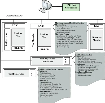
The most commonly accepted definition of flexibility is the ability to take up different positions or alternatively the ability to adopt a range of states [32]. Many different authors have defined many different types of flexibilities (machine, process, product, operation, routing, volume, production and expansion flexibility) in the literature [33-37]. Here we consider the flexibility control function as machine flexibility and tool flexibility. Browne et al. [38] defined machine flexibility as the ease of change to process a given set of part types. Buzacott [39] clarifies machine flexibility as the ability of the system to cope with changes. There are three technical constraints re-lated to a machining center: number and capacity of ma-chine-tools, local input/output buffer (LIB/LOB) size and operative efficiency. Das and Nagendra [40] define ma-chine flexibility of a machining center as the ability of performing more than one type of processing operation efficiently. Therefore, machine flexibility is measured by the number of operations that a workstation processes and the time needed to switch from one operation to an-other. The more operations a workstation processes and the less time switching takes, the higher the machine flexibility becomes [37]. Figure 1 shows the proposed adaptive flexibility control functions of the FMS shop floor.
FMS Host Co-Simulator
C.N.C
T
ool
Magaz
in
e Machine
Tool
LIB/LOB
C.N.C
T
ool
Magazi
ne Machine
Tool
LIB/LOB
P.L.C
Measuring Machine
P.
L
.C
Part Preparation Load/Unload
P.
L
.C
Tool Preparation
Machining Center Flexibility Function Machine Setup
Machining center identification* No. of machine tools Information on tool magazine Machine tool capacity
Machining Process
Machine state (Processing-Idle-Failed) Machining rules (RAN-SQL-LULIB) Load part from LIB (Local Input Buffer) Unload part to LOB (Local Output Buffer) Load/Unload parts from/to Central Buffer Remain process time
Operative efficiency
Part Control Function Part Setup
Part identification* Inter arrival time , Due date Earliness/Tardiness penalty Information on fixturing & Palletizing
Part Routing
NO. Of operation, Tools required Alternative machining center Operation time, Shared operation Sequence selection option
Part Process Planning
Part routing Machining operation
Tool Flexibility Control Function Tool Setup
Tool identification* Information on fixturing Tool magazine capacity Tool life, Tool slot, Kit ID
Tool Routing
Part identification
NO. of operation , Operation time Alternative machining center Tools required, Sequence selection ToolingStrategy (SPT-SOT-FCFS-FNOP-LTL)
Tool Replacement
Tool routing, Tool Changeover Machining operation Alternative tools
[image:3.595.79.523.97.534.2]Industrial FieldBus
Figure 1. FMS shop floor flexibility control functions
The tool magazine capacity is an influential factor in determining the flexibility of the system. A proper tool management is needed to control processing of parts and enhance the flexibility to variety of parts. It is important to design a tool management control function so that the proper tools are available at the right machine at the de-sired time for processing of scheduled parts.
The work-order processing and part control system essentially drives other control functions. This module concerns the determination of a subset of part types from a set of part types for processing.
A number of criteria can be used for selecting a set of part types for processing (i.e. due date, inter arrival time,
requirement of tools, operation time, shared operation, operations sequence).
3. FMS Adaptive Controller Architecture
3.1 FMS Configuration Parameters
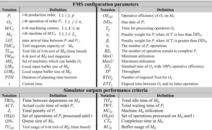
The following notations and criteria are utilized in devel-oping the rule-based model of the FMS controller ad-dressed in this research. Table 1 represents the notations.
Table 1. FMS configuration parameters and performance criteria
FMS configuration parameters
Notation Definition Notation Definition
Pi i-th production order, 1i p OEijkl Operative efficiency of Oij on Mkl
Oij j-th operation of order Pi, 1 jni DDPi Due date of Pi
M/Ck k-th machining centers, 1km Tij Time for processing operation Oij
Mkl l-th machine of M/Ck, 1lLk αi Penalty weight for Pi when ACTi is less than DDPi
IATi inter arrival time between Pi and Pi-1 βi Penalty weight for Pi when ACTi is greater than DDPi
TMCkl Tool magazine capacity of Mkl ni The number of Pi operations.
TLhkl Tool life of h-th tool of Mkl (time based) REi The number of operation remain to complete Pi
TMhkl h-th tool of Mkl tool magazine MinU Minimum utilization
MSij Set of machines which can handle Oij MaxU Maximum utilization
LIBkl Local input buffer size of Mkl STij Standard time of Oij with 100% operative efficiency
LOBkl Local output buffer size of Mkl TP Throughput
PTH Duration of planning time horizon RTOij Number of required Tool for Oij
t Current time ETTij Elapsed time between Oij and its latter operation
Simulator outputs performance criteria
Notation Definition Notation Definition
TBDkl Time between departures on Mkl TITkl Total idle timeof Mkl
ACTi Actual cycle time of order Pi TWTi Total waiting time of Pi
Zi Total penalty of Pi MUkl Machine Mkl utilization
OSi(t) Set of operations of Pi processed until t OSkl(t) Set of operations processed on Mkl until t
QMkl Queue size of Mkl CTkl Completion time in Mkl
TUhkl Tool usage of h-th tool of Mkl (time based) BUkl Buffer usage of Mkl
Table 2. Binary control flags
Variable Definition Variable Definition
OAijkl wise it is equal to 0 Equal to 1 if Oij is assigned to Mkl, other- MIUkl Equal to 1 if machineequal to 0 Mkl is in use; otherwise it is
TMLhijkl Equal to 1 if on M TMhkl load to perform Oij
kl and equal to 0 if unloads RTMh BSAkl
Equal to 1 if buffer space of Mkl is available;
other-wise it is equal to 0
PCi Equal to 1 if equal to 0 Pi complete otherwise it is MBkl Equal to 1 if machineis equal to 0 Mkl is bottleneck; otherwise it
λi Equal to 1 if otherwise it is equal to 0 ACTi is less than DDPi, ODijkl Equal to 1 if wise it is equal to 0 Oij is done on Mkl, and depart it;
other-APOi Equal to 1 if Pi should be scheduled next
otherwise it is equal to 0 PAi Equal to 1 if Pi arrive otherwise it is equal to 0
OWij Equal to 1 if Ootherwise it is equal to 0 ij is waiting for process;
flexibility characteristics of an FMS. Table 2 shows the binary control flags (BCF’s).
3.2 Simulation-Based Intelligent Decision Support System
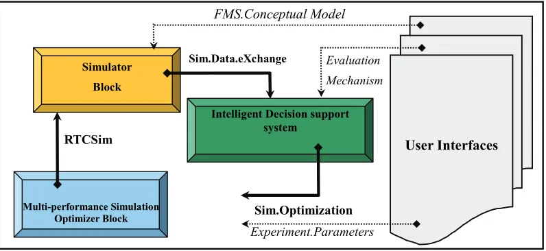
Figure 2 shows the combination between simulation and intelligent decision support system as for FMS adaptive control. The figure shows the cooperation between IDSS and the simulator module. The current configuration pa-rameters of the FMS are read by user interface and are used as the input data to build conceptual model. The simulation model will evaluate the current shop per-formance, such as actual cycle time, tool and buffer utilization. This process continues until a satisfying and controllable shop floor configuration is reached.
Intelligent Decision support system
Multi-performance Simulation Optimizer Block
Simulator Block
Sim.Data.eXchange
Sim.Optimization FMS.Conceptual Model
RTCSim
Evaluation Mechanism
User Interfaces
[image:5.595.100.498.95.278.2]Experiment.Parameters
Figure 2. The structure of simulation-based IDSS for FMS adaptive control
of operators and system control flags are recorded in separate databases. Sequence of jobs is used to control the flow of parts through the system. The first step to estimate the performance criteria is assigning the opera-tions to machines and scheduling the operaopera-tions on each machine.
The above posteriori adaptive control mechanism em-ploys a simulator block to predict different performance criteria of the FMS conceptual model. The simulator contains the discrete event simulation model and is able to measure several FMS performance criteria depending on the different inputs. The simulation results are then for-warded between external interfaces belonging to different external models. On the other hand, these interfaces
han-dle the necessary communications with the simulation and coordinate IDSS control signal transformations into the simulator.
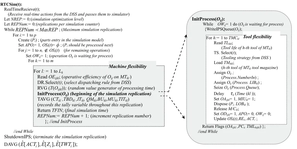
Sequence of jobs is used to control the flow of parts through the system. The first step to estimate the per-formance criteria of FMS is assigning the operations Oij to machining centers and extracting the set OSMkl(t)includes operations processed on M/Ck until t. The real time adap-tive control framework is based on affiliating all current events and expected future event to a time tag for process synchronization. The following pseudo-code shows the initialization phase of the simulation in order to configure the FMS conceptual model.
The initialization phase should be run in execution
mode using the function RealTimeInitialize(t) to syn-chronize simulation logic with an external process of FMS controller system. The module RTCSim(t) represents FMS events simulation to handle machine and tool flexibility.
The simulation clock is set to the real-time clock of the operating FMS system and all other simulation processes
are initiated by InitProcess(Oij). Because of the random-ness of processing times in each replication, the expecta-tions of system outputs are estimated by sample means. The function TAVG ACT TU( i, hkl,BUkl) records the values of system outputs throughout each replication and finally estimates the expectation of these statistics
FMSConfigParam()
Read Number of parts, machining centers and planning horizon (p,m,PTH); For i: = 1to p Read Number of parts operations and due date (ni, DDPi, IATi, αi, βi);
For k: = 1to m Read Number of machines at each machining centers (Lk);
For k: = 1 to m initialize Machining Centers ResourcesM/Ck, Capacity;
For k: = 1 to m
For l: = 1 to Lk initialize Machine Tools, Tool magazine and buffers (MTkl, TMCkl, LIBkl, LOBkl);
For i: = 1 to p
For j: = 1 to ni
Initialize queue used to hold part operations (Oij (Process.Queue));
Read (processing time of each operation (Oij , Tij , STij , MSij , ETTij , RTOij);
InitTime(t); (Initialize simulation current time)
RTCSim(t):
RealTimeRecieve(t);
(Receive real-time actions from the DSS and passes them to simulator) Let NREP:= 0;(simulation optimization level)
Let REPNum:= 0;(replications per simulation counter)
WhileREPNum MaxREP ; (Maximum simulation replications) For i:= 1to p
Create (Pi) ; (parts entry in the simulation model)
Set APOi= 1, OSi(t)= ф ; (Pi should be processed next)
For j:= 1to niOSi(t) (for remaining operations)
Set OWij= 1; (operation Oij is waiting for process)
For k:= 1to m
//end While
ShutdownIPS; (terminate the simulation replication) DAVG( [E ACT E Zˆ i], [ ], [ˆ i E TWTˆ i]);
(Return the average of time-persistent statistics throughout all replications)
InitProcess(Oij):
While OWij= 1 do (Oij is waiting for process)
{WriteIPSQueue(Oij);
Return Flags (OAijkl ,PCi, TMLhijkl) }; //end While
For h:= 1to TMCkl
Read TLhkl;
(Tool life of h-th tool of MTkl)
TS. Select(t);
(Tooling strategy from DSS ) Load TMhkl;
(h-th tool of MTkl tool magazine)
Assign Oij ;
(Process.NumberIn) ; Assign Oij(Process. LIBkl) ;
Seize Oij(Process.Queue);
Delay τij(Time (kl ));
Set OAijkl= 1, MIUkl= 1;
Dispose (Pi. LOBkl );
Release M/Ckl;
Set ODijkl= 1, APOi= 0,OWij= 0;
Update OSi(t),REi, ACTi ;
Tool flexibility
For l: = 1 to Lk
Read OEijkl; (operative efficiency of Oij on MTkl)
DR.Select(t); (select dispatching rule from DSS)
RVG (T(Oijkl)); (random value generator of processing time)
InitProcess(Oij) (beginning of the simulation replication) TAVG (CTkl ,TBDkl ,ITkl, QMkl,BUkl,MUkl,TITkl)
(records the tally variable throughout this replication) Return TFIN; (final simulation time)
REPNum:= REPNum + 1; (increment replication number) }; //end InitProcess
Machine flexibility
through the average functionDAVG E ACT( [ˆ i], E TUˆ[ hkl], ˆ[ kl])
E BU over MaxREP simulation replications. The number of replications per simulation (MaxREP) should be set to the minimum number necessary to obtain a re-liable estimate of performance criteria.
Based on the results obtained at each level of optimi-zation (NREP) and exchanging them with IDSS, addi-tional number of replications may be re-simulated for each design. The expected value of FMS performance criteria are extracted under design ijkl,OAijkl
. The E ACTˆ[ i |
, ],
ijkl OAijkl
E TUˆ[ hkl|ijkl,OAijkl],
ˆ[
| , ]
kl ijkl ijkl E BU OA represent the stochastic effects of system output by sam-ple mean. The ultimate goal is to find the solution that optimizes the value of these performance criteria. The optimization procedure uses the outputs from the simula-tion model of previous NREP to construct a response surface at each simulation optimization level of
, |
ijkl OAijkl NREP r
and to extract the next level of ,
ijkl OAijkl
as an input to the model.
To control the external processes of FMS, the simulator block and IDSS are synchronized via simulation data exchange Sim.Data.eXchange(IDSS). The IDSS ana-lyzes outputs of simulation model to control the real-time status of FMS after receiving these results by
Real-TimeSend() function. The IDSS then sends appropriate
control signals of beginning operation to the correspond-ing entities when an event is occurred. Proposcorrespond-ing the
[image:6.595.60.543.106.348.2]adaptive controller with this structure allows modeling of synchronization mechanism between FMS entities and transmission times for messages exchanged between the IDSS and simulator.
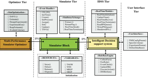
Figure 3 schematically describes the inter-process synchronization between different components of co- simulator. The approach for adaptive controller designing is built around the theory of supervisory control based on exchanging simulation outputs with an event-condi-tion-action real time system. The proposed system uses a posteriori adaptive control mechanism that also is an online control method acting after the event occurs versus such popular reactive control method.
The simulator can trigger the rule-based IDSS to gen-erate the appropriate control policy. The simulator block sends messages to the external rule-based system to in-dicate simulated results from FMS by RealTimeSend(). The rule-based IDSS interprets these results and sends appropriate action messages back to the simulator and user to indicate the instructions to be done.
3.3 Rule Production for FMS Real Time Simulation-Based Controller
The IDSS collect the facts into appropriate data base using
‹‹Event Handler››
♀ CEL,FEL
♀ InitTime()
♀ Create()
♀ InitProcess()
♀ Assign()
♀ Set()
♀ Update()
♀ TAVG()
‹‹RealTimeModule››
♀ RealTimeInitialize()
♀ UpdateTime()
♀ RealTimeRecive()
♀ RealTimeTerminate()
♀ ReadIPSQueue()
♀ WriteIPSQueue()
♀ ShutdownIPS ()
‹‹UserInterface››
♀ FMSConfigParam()
♀ SpecifyCritera()
♀ ExperimentParam()
♀ DefineDataBase()
‹‹RuleBaseEngine
♀ CollectFact()
♀ FireRule()
♀ EventCheck()
♀ UpdateDB()
♀ ExecuteAction()
♀ DSSReSim() ‹‹SimDataeXchange››
♀ Extract ()
♀ ReturnFlag ()
♀ RealTimeSend()
♀RealTimeTerminate()
Simulator Block
Intelligent Decision support system
‹‹SimOptimization››
♀ DAVG ()
♀ Estimate()
♀ DesignExperiment()
♀ ExperimentExe()
♀ RespEstimate()
♀ EvaluteCriteria()
IPS
‹‹RESOURCES››
♀ Seize()
♀ Delay()
♀ Release()
♀ Dispose()
‹‹VARIABLES››
♀ TNOW
♀ TFIN
♀ MREP
♀NREP
User Interface Tier IDSS Tier
Simulator Tier
Multi-Performance Simulator Optimizer
IPS Optimizer Tier
[image:7.595.65.537.98.349.2]Initialization
Figure 3. Real time simulation data exchange via inter-process synchronization
tation techniques are used for preventing ineffective re-dundancy at concurrent firing of rules and high degree of parallelism. This knowledge-based IDSS is aimed at pro-viding a powerful control on different operations of FMS. It acts as a cell manager which may work alongside the operating cell-oriented part and tool management system. These sections describe the knowledge representation through a set of control rules. Design of IDSS controller focuses on the development of appropriate Event-Condi-tion-Action (ECA) rules for tuning control parameters. These rules are formulated by the techniques of data gathering and knowledge elicitation to construct IDSS. The IDSS is able to obtain feedback results from the on-line system of simulator. These results are very sig-nificant and let the expert system to re-simulate if the performance criteria are not desirable.
The rules applied in this paper are structured in the following form and consist of three segments: event type, condition and action:
When ‹Event1 , Event2 ,Event3 , … ›
If ‹Condition1 , Condition2 , Condition3 , … › Then ‹Action1 , Action2 , Action3 ,… ›
Event type: This tag specifies that analysis of condi-tion should be done once the events take place.
Condition: This segment of ECA rules specifies a list of conditions. In order to trigger an action rule, all condi-tions should be satisfied. These condicondi-tions refer to a log-ical assertion of the FMS states extracted by the simula-tor module RTCSim(t).
Action: This segment specifies actions which may
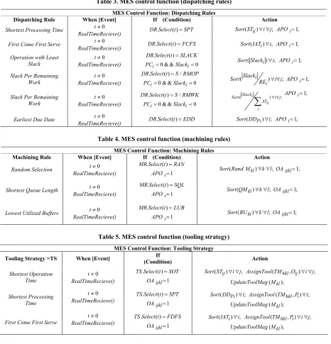
consist of a list of operations. Whenever an action rule is triggered by an event, the operations being in its action list will be initiated sequentially. The proposed rule- based system for manufacturing execution system pro-vides the parts sequence list to the multi-purpose ma-chines available and then the operation assignment and task proportions of parts on related machines. The output can be manipulated by changing the rules and strategies entered at the expert system query stage. Table 3 illus-trates MES control function about dispatching rules.
For each part Pi the slack index is defined as:
1 , i
n
i Pi ij
j
Slack DD ST t i
. The function Sort(array)finds the maximum or minimum value in the array and the binary flag APOi specifies the next scheduled part. Table 4 illustrates MES control function for machining rules in the FMS.
The binary flag OAijkl specifies the assignment of op-eration Oijto machine Mkl. Table 5 illustrates MES con-trol function for tooling strategy in the FMS.
Operative efficiency of doing operation Oij on Mkl is defined as OEijkl and thus tool usage can be considered as
(1 ); , ,
hkl ij ijkl
TU T OE h k l . For each executable
Table 3. MES control function (dispatching rules)
MES Control Function: Dispatching Rules
Dispatching Rule When [Event] If (Condition) Action
Shortest Processing Time t0
RealTimeRecieve() DR Select t. ( )SPT Sort ST( ij) i j; APOi1;
First Come First Serve t0
RealTimeRecieve() DR Select t. ( )FCFS Sort IAT( i)i; APOi1; Operation with Least
Slack
0
t
RealTimeRecieve()
. ( )
DR Select t SLACK
0 & & 0
i i
PC Slack Sort Slack( i)i; APOi1;
Slack Per Remaining Work
0
t
RealTimeRecieve()
. ( ) /
DR Select t S RMOP
0 & & 0
i i
PC Slack ( i i) ;
Slack
Sort RE i j APOi1;
Slack Per Remaining Work
0
t
RealTimeRecieve()
. ( ) /
DR Select t S RMWK
0 & & 0
i i
PC Slack
( i ) ;
ij j Slack
Sort i j
ST
APOi1;Earliest Due Date t0
RealTimeRecieve() DR Select t. ( )EDD Sort DD( Pi)i; APOi1;
Table 4. MES control function (machining rules)
MES Control Function: Machining Rules
Machining Rule When [Event] If (Condition) Action
Random Selection t0
RealTimeRecieve()
. ( )
MR Select t RAN
1 i
APO Sort Rand M( kl) k l;OAijkl1;
Shortest Queue Length t0 RealTimeRecieve()
. ( )
MR Select t SQL
1 i
APO Sort QM( kl) k l; OAijkl1;
Lowest Utilized Buffers t0 RealTimeRecieve()
. ( )
MR Select t LUB
1 i
APO Sort BU( kl) k l;OAijkl1;
Table 5. MES control function (tooling strategy)
MES Control Function: Tooling Strategy
Tooling Strategy =TS When [Event] (Condition) If Action
Shortest Operation Time 0 t RealTimeRecieve() . ( )
TS Select t SOT
1 ijkl
OA
( ij) ;
Sort ST i j AssignTool TM( hkl,Oij) i j;
( kl);
UpdateToolMag M
Shortest Processing Time
0
t
RealTimeRecieve() TS Select t. ( )1SPT ijkl
OA
( Pi) ;
Sort DD i AssignTool TM( hkl, )Pi i; ( kl);
UpdateToolMag M
First Come First Serve
0
t
RealTimeRecieve()
. ( )
TS Select t FDFS
1 ijkl
OA
( i) ;
Sort IAT i AssignTool TM( hkl i, )P i j; ( kl);
UpdateToolMag M
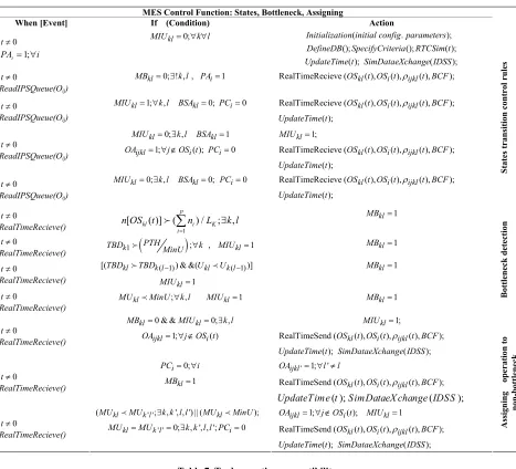
dynamically rebuild new configuration and replicate si-mulation module RTCSim(t). Table 6 contains the rules for control of transition of different states in FMS, bot-tleneck detection and resolving, assigning operation to a non-bottleneck machining centers.
For each part Pi actual cycle time is defined
as:
kl OS j ijkl ij ijkl ij i OE ST ETTACT and the penalty is
defined as:
p i i P i i i i i P i ii DD ACT ACT DD
Z 1 ) )( 1 ( ) ( .
4. Experimental Study
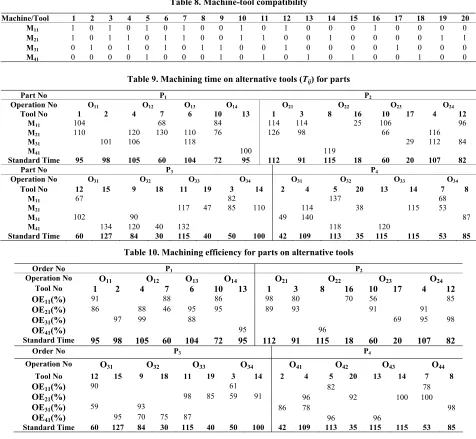
The problem presented has been adopted in this paper to validate the proposed method by Sarin and Chen [43]. The model presents machine loading and tool allocation problem in FMS with tool life and magazine capacity. The FMS model includes tool and machine alternatives. The experiment was done on a FMS with four machining centers. Tables 7 and 8 show tool-operation and machine -tool compatibility.
Table 6. MES control function
MES Control Function: States, Bottleneck, Assigning
When [Event] If (Condition) Action
0
t
i PAi1;
0; kl
MIU k l Initialization initial config parameters( . );
(); (); ( );
DefineDB SpecifyCriteria RTCSim t
( );
UpdateTime t SimDataeXchange IDSS( ); 0
t
ReadIPSQueue(Oij)
0; ! , kl
MB k l, 1PAi RealTimeRecieve (OSkl( ),t OS ti( ),ijkl( ),t BCF);
0
t
ReadIPSQueue(Oij)
1; , 0;
kl kl
MIU k l BSA PCi0 RealTimeRecieve (OSkl( ),t OS ti( ),ijkl( ),t BCF); ( );
UpdateTime t
0
t
ReadIPSQueue(Oij)
0; , 1
kl kl
MIU k l BSA
1; ( );
ijkl i
OA j OS t PCi0
1; kl
MIU
RealTimeRecieve (OSkl( ),t OS ti( ),ijkl( ),t BCF); ( );
UpdateTime t
0
t
ReadIPSQueue(Oij)
0; , 0;
kl kl
MIU k l BSA PCi0 RealTimeRecieve (OSkl( ),t OS ti( ),ijkl( ),t BCF); ( ); UpdateTime t St at es transit ion cont rol rules 0 t
RealTimeRecieve() [ ( )] ( 1 ) / ; ,
p
kl i K
i
n OS t n L k l
MBkl1
0
t
RealTimeRecieve() k1
;PTH
TBD MinU k , MIUkl1 MBkl1
0
t
RealTimeRecieve()
( 1) ( 1)
[(TBDklTBDk l ) & &(UklUk l )]
1 kl MIU 1 kl MB 0 t RealTimeRecieve() ; , kl
MU MinU k l MIUkl1 MBkl1 Bottleneck
det ecti on 0 t RealTimeRecieve()
0 & & 0; ,
kl kl
MB MIU k l
1; ( )
ijkl i
OA j OS t
1; kl
MIU
RealTimeSend (OSkl( ),t OS ti( ),ijkl( ),t BCF); ( );
UpdateTime t SimDataeXchange IDSS( );
0
t
RealTimeRecieve()
0; i PC i
1 kl
MB
' 1; '
ijkl
OA l l
RealTimeSend (OSkl( ),t OS ti( ),ijkl( ),t BCF);
( );
UpdateTime t SimDataeX change IDSS( );
0
t
RealTimeRecieve()
' '
(MUklMUk l;k k l l, ', , ') || (MUklMinU);
' ' 0; , ', , '; 0
kl k l i
MU MU k k l l PC
1; ( ); 1
ijkl i kl
OA j OS t MIU
RealTimeSend (OSkl( ),t OS ti( ),ijkl( ),t BCF); ( );
UpdateTime t SimDataeXchange IDSS( );
Assigning opera
ti
on
to
non-bottlen
eck
Table 7. Tool-operation compatibility
Part/Tool 1 2 3 4 5 6 7 8 9 10 11 12 13 14 15 16 17 18 19 20
O11 1 1 0 0 0 0 0 0 0 0 0 0 0 0 0 0 0 0 0 0
O12 0 0 0 1 0 0 1 0 0 0 0 0 0 0 0 0 0 0 0 0
O13 0 0 0 0 0 1 0 0 0 0 0 0 0 0 0 0 0 0 0 0
P1
O14 0 0 0 0 0 0 0 0 0 1 0 0 1 0 0 0 0 0 0 0
O21 1 0 1 0 0 0 0 0 0 0 0 0 0 0 0 0 0 0 0 0
O22 0 0 0 0 0 0 0 1 0 0 0 0 0 0 0 1 0 0 0 0
O23 0 0 0 0 0 0 0 0 0 1 0 0 0 0 0 0 1 0 0 0
P2
O24 0 0 0 1 0 0 0 0 0 0 0 1 0 0 0 0 0 0 0 0
O31 0 0 0 0 0 0 0 0 0 0 0 1 0 0 1 0 0 0 0 0
O32 0 0 0 0 0 0 0 1 0 0 0 0 0 0 0 0 1 0 0
O33 0 0 0 0 0 0 0 0 0 0 1 0 0 0 0 0 0 0 1 0
P3
O34 0 0 1 0 0 0 0 0 0 0 0 0 0 1 0 0 0 0 0 0
O41 0 1 0 1 0 0 0 0 0 0 0 0 0 0 0 0 0 0 0 0
O42 0 0 0 0 1 0 0 0 0 0 0 0 0 0 0 0 0 0 0 1
O43 0 0 0 0 0 0 0 0 0 0 0 0 1 1 0 0 0 0 0 0
P4
O44 0 0 0 0 0 1 1 0 0 0 0 0 0 0 0 0 0 0 0 0
[image:9.595.67.534.537.721.2]Table 8. Machine-tool compatibility
Machine/Tool 1 2 3 4 5 6 7 8 9 10 11 12 13 14 15 16 17 18 19 20
M11 1 0 1 0 1 0 1 0 0 1 0 1 0 0 0 1 0 0 0 0
M21 1 0 1 1 0 1 1 0 0 1 1 0 0 1 0 0 0 0 1 1
M31 0 1 0 1 0 1 0 1 1 0 0 1 0 0 0 0 1 0 0 0
M41 0 0 0 0 1 0 0 0 1 0 1 0 1 0 1 0 0 1 0 0
Table 9. Machining time on alternative tools (Tij) for parts
Part No P1 P2
Operation No O11 O12 O13 O14 O21 O22 O23 O24
Tool No 1 2 4 7 6 10 13 1 3 8 16 10 17 4 12
M11 104 68 84 114 114 25 106 96
M21 110 120 130 110 76 126 98 66 116
M31 101 106 118 29 112 84
M41 100 119
Standard Time 95 98 105 60 104 72 95 112 91 115 18 60 20 107 82
Part No P3 P4
Operation No O31 O32 O33 O34 O31 O32 O33 O34
Tool No 12 15 9 18 11 19 3 14 2 4 5 20 13 14 7 8
M11 67 82 137 68
M21 117 47 85 110 114 38 115 53
M31 102 90 49 140 87
M41 134 120 40 132 118 120
Standard Time 60 127 84 30 115 40 50 100 42 109 113 35 115 115 53 85
Table 10. Machining efficiency for parts on alternative tools
Order No P1 P2
Operation No O11 O12 O13 O14 O21 O22 O23 O24
Tool No 1 2 4 7 6 10 13 1 3 8 16 10 17 4 12
OE11(%) 91 88 86 98 80 70 56 85
OE21(%) 86 88 46 95 95 89 93 91 91
OE31(%) 97 99 88 69 95 98
OE41(%) 95 96
Standard Time 95 98 105 60 104 72 95 112 91 115 18 60 20 107 82
Order No P3 P4
Operation No O31 O32 O33 O34 O41 O42 O43 O44
Tool No 12 15 9 18 11 19 3 14 2 4 5 20 13 14 7 8
OE11(%) 90 61 82 78
OE21(%) 98 85 59 91 96 92 100 100
OE31(%) 59 93 86 78 98
OE41(%) 95 70 75 87 96 96
[image:10.595.147.448.558.723.2]Standard Time 60 127 84 30 115 40 50 100 42 109 113 35 115 115 53 85
Table 11. Operation assignment and task proportion (
ijkl) and tool loadPart/Machine M11 M21 M31 M41
O11 0.27 (1) 0.73 (2)
O12 0.81 (7) 0.19 (4)
O13 0.78 (6) 0.22 (6)
P1
O14 0.12 (10) 0.88 (10)
O21 0.89 (1) 0.11 (3)
O22 0.79 (16) 0.21 (8)
O23 0.75 (10) 0.25 (17)
P2
O24 0.22 (12) 0.78 (12)
O31 0.91 (12) 0.09 (12)
O32 0.79 (9) 0.21 (18)
O33 1 (19)
P3
O34 0.35 (3) 0.65 (14)
O41 0.66 (4) 0.34 (2)
O42 0.48 (20) 0.52 (5)
O43 1 (12)
P4
Table 12. Difference between the proposed method and the heuristic method of [43]
Total Actual Cycle Time
Total Idle Time
Total Time between Departure
Total Waiting Time
Penalty
Proposed system 2703 441 35 127 48.5
(Earliness) Classis mathematical
method
3108 731 63 463 154
[image:11.595.85.510.201.287.2](Tardiness)
Table 13. Statistical analysis of difference between the proposed and mathematical method
Actual Cycle Time
Idle Time Time between Departure
Waiting Time
Mean 2705.68 442.936 34.360 128.226
StDev 16.68 9.932 2.029 10.436
SEMean 0.85 0.507 0.104 0.533
T-Value –472.54 –568.36 –276.55 –628.64
Sample Size = 384
P-Value 0.000 0.000 0.000 0.000
Table 10 represents machining efficiency of operation allocation on alternative tools.
It is assumed that due date (DD = 2800), αi = βi = 0.5, and LIBkl = LOBkl = 15. Tool magazine capacity and tool life are considered 20 and 100, respectively. Manufac-turing execution system also includes dispatching rules (SPT), tooling strategies (FCFS) and machining rules (SQL). Table 11 shows the operation assignment and task proportion according to the rules of the proposed method.
Table 12 represents the difference of total actual cycle time, total idle time, total time between departures and total waiting time between the proposed rule-based sys-tem and the mathematical method.
The solution obtained from proposed method creates a balanced and controlled actual cycle time on machining centers. The proposed approach outperforms the heuristic method in terms of the total actual cycle time, total idle time, total time between departures and total waiting time. The proposed system presents 48.5 units of earliness pe-nalty despite the 154 unit of tardiness pepe-nalty of mathe-matical method. To show the effects of difference be-tween the proposed method outputs and ِclassic mathe-matical method, statistical analysis is given as shown in Table 13.
The aforementioned results verify and validate the FMS shop floor links to the supervisory control of ma-chine and tool flexibility. Different scenarios of per-formance criteria levels demonstrate effectiveness of the proposed method for the system control. The proposed method is also efficient in terms of the computation time which is highly important for the real time control of a manufacturing system. The proposed real-time simula-tion-based intelligent decision support system provides a real time control mechanism for improving performance of a flexible manufacturing shop floor.
5. Conclusions
This paper presents an intelligent decision support sys-tem to tackle the production control of a FMS. Develop-ment of the present knowledge-based system is aimed at integrating an ECA rule-based system and a simulator module to ease the cell adaptive supervisory control. A novel architecture of this intelligent adaptive controller prototype which is based on a real-time simulator core has been developed and presented to validate the pro-posed approach.
The FMS shop floor data are gathered and stored into the appropriate databases over time. The adaptive control mechanism employs a real time discrete event simulator to predict performance of the given system during the remaining time of planning horizon. The current state of the FMS performance criteria from the simulator is then stored on the appropriate databases. The proposed me-thod provides an applicable and efficient framework for real-time control of the shop floor in flexible manufactur-ing system. The criteria considered to measure perform-ance of the system shows that the proposed approach is effective and efficient in controlling shop floor. The main contributions of this paper can be summarized as follows. 1)Designing real time ECA rules according to feed forward reasoning with the high degree of granularity.
2)Reinforcement of the expert system reasoning nique using data mining and knowledge-elicitation tech-niques.
3)Proposed method constitutes the framework of adaptive controller supporting the ordination and co-operation relations by integrating a real time simulator and an IDSS for implementing dynamic strategies.
4)Avoiding ineffective redundancy at concurrent fir-ing of rules and high degree of parallelism
adap-tive control mechanism that also is an online control me-thod acting after the event occurs versus such popular reactive control method.
As a result, the proposed system is suitable for differ-ent control frameworks on an existing flexible manufac-turing system considering the physical constraints and the production objectives. Furthermore, the system illus-trates the potential of using the intelligent rule-based DSS for adaptive control of modern industrial plants. Future researches may concentrate on the application of other types of flexibility in shop floors using simulation- based predictive controllers.
REFERENCES
[1] J. A. Buzacott and D. D. Yao, “Flexible Manufacturing Systems: A Review of Analytical Models,” Management
Science,Vol. 32, No. 7, 1986, pp. 890-905.
[2] J. R. Dixon, “Measuring Manufacturing Flexibility: An Empirical Investigation,” European Journal of
Opera-tional Research, Vol. 60, 1992, pp. 131-143.
[3] R. Jaikumar, “Flexible Manufacturing Systems: Manage- ment Perspective,” Division of Research, Harvard Busi-ness School, 1984.
[4] J. S. Edghill and A. Davies, “Flexible Manufacturing Systems—The Myth and Reality,” International Journal
of Advanced Manufacturing Technology, Vol. 1, No. 3,
1985, pp. 37-54.
[5] M. D. Byrne and P. Chutima, “Real-Time Operational Control of an FMS with Full Routing Flexibility,”
Inter-national Journal of Production Economics, Vol. 51, No.
2, 1997, pp. 109-113.
[6] Y. M. Moon, “Reconfigurable Machine Tool Design,” In: A. I. Dashchenko, Ed., Reconfigurable Manufacturing
Systems and Transformable Factories, Springer, 2006, pp.
112-139.
[7] R. Tawegoum, E. Castelain and J. C. Gentina, “Real- Time Piloting of Flexible Manufacturing Systems,” Euro-
pean Journal of Operational Research, Vol. 78, No. 2,
1994, pp. 252-261.
[8] K. E. Stecke and L. Kim, “A Flexible Approach to Part Type Selection in Flexible Flow Systems Using Part Mix Ratios,” International Journal of Production Research,
Vol. 29, No. 1, 1991, pp. 53-75.
[9] C. Basnet and J. H. Mize, “Scheduling and Control of Flexible Manufacturing Systems: A Critical Review,” In-ternational Journal of Computer Integrated Manufactur-ing, Vol. 7, No. 6, 1994, pp. 340-355.
[10] J. Ayel, “Supervising Conflicts in Production Manage-ment,” International Journal of Computer Integrated
Manufacturing, Vol. 8, No. 1, 1995, pp. 54-63.
[11] H. Seifoddini and J. Zhang, “Application of Simulation and Petri Net Modelling in Manufacturing Control Sys-tems,” International Journal of Production Research, Vol. 34, No. 1, 1996, pp. 191-207.
[12] E. Szelke and L. Monostori, “Reactive Scheduling in Real-Time Production Control,” Modeling Manufacturing
Systems, Springer, New York, 1999.
[13] Z. Guo, W. Wong, S. Leung, J. Fan and S. Chan, “A Ge-netic-Algorithm-Based Optimization Model for Schedul-ing Flexible Assembly Lines,” International Journal of
Advanced Manufacturing Technology, Vol. 36, No. 1-2,
2006, pp. 156-168
[14] D. J. Van der Zee, “Modeling Decision Making and Con-trol in Manufacturing Simulation,” International Journal
of Production Economics, Vol. 100, No. 1, 2006, pp.
155-167.
[15] F. T. S. Chan, R. Bhagwat and S. Wadhwa,
, Vol.
2006, pp. 1-24.
[16] G. Habchi and C. Berchet, “A Model for Manufacturing Systems Simulation with a Control Dimension,”
Simula-tion Modelling Practice and Theory, Vol. 11, No. 1, 2003,
pp. 21-44.
[17] B. P. Douglass, “Real-Time Design Patterns: Robust Scalable Architecture for Real-Time Systems,” Addison- Wesley, 2003.
[18] L. Yao, W. Browne, I. Postlethwaite, T. Ozen, P. Atack, M. Mar and S. Lowes, “Architecture for Intelligent Knowledge-Based Supervisory Control of Rolling Mills,”
IFAC Workshop on New Technologies for Automation of
Metallurgical Industry, Shanghai, China, 2003, pp. 162-
167.
[19] G. Guariso, M. Hitz and H. Werthner, “An Integrated Simulation and Optimization Modelling Environment for Decision Support,” Decision Support Systems, Vol. 16, No. 2, 1996, pp. 103-117.
[20] C. Gertosio, N. Mebarki and A. Dussauchoy, “Model-ing and Simulation of the Control Framework on a Flexi-ble Manufacturing System,” International Journal of
Production Economics, Vol. 64, No. 1-3, 2000, pp. 285-
293.
[21] J. W. Fowler and O. Rose, “Grand Challenges in Model-ing and Simulation of Complex ManufacturModel-ing Systems,”
SIMULATION—Transactions of the Society for
Model-ling and Simulation International, Vol. 80, No. 9, 2004,
pp. 469-476.
[22] F. T. S. Chan and H. Chan, “A Comprehensive Survey and Future Trend of Simulation Study on FMS Schedul-ing,” Journal of Intelligent Manufacturing, Vol. 15, No. 1, 2004, pp. 87-102.
[23] G. R. Drake, J. S. Smith and B. A. Peters, “Simulation as a Planning and Scheduling Tool for Flexible Manufac-turing Systems,” Proceedings of the 1995 Winter
Simula-tion Conference, 1995, pp. 805-812.
Ad-vanced ManufacturingTechnology, Vol. 19, No. 11, 2002, pp. 830-849.
[25] S. Chong, A. Sivakumar and R. Gay, “Simulation-Based Scheduling for Dynamic Discrete Manufacturing,”
Pro-ceedings of the 2003 Winter Simulation Conference, New
Orleans, Louisiana, USA, 2003.
[26] R. W. Brennan and O. William, “Performance Analysis of a Multi-Agent Scheduling and Control System for Manu-facturing,” Production Planning Control, Vol. 15, No. 2, 2004, pp. 225-235.
[27] R. Schelasin and J. Mauer, “Creating Flexible Simulation Models,” IEE Solutions, Vol. 5, 1995, pp. 50-67.
[28] A. Anglani, A. Grieco, M. Pacella and T. Tolio, “Object- Oriented Modeling and Simulation of Flexible Manufac-turing Systems: A Rule-Based Procedure,” Simulation
Modelling Practice and Theory, Vol. 10, No. 3-4, 2002,
pp. 209-234.
[29] D. Arnott and G. Pervan, “A Critical Analysis of Deci-sion Support Systems Research,” Journal of Information
Technology, Vol. 20, No. 2, 2005, pp. 67-87
[30] R. W. Brennan, “Towards Real-Time Distributed Intelli-gent Control: A Survey of Research Themes and Applica-tions,” IEEE Transactions on Systems, Man, and
Cyber-netics, Vol. 37, No. 5, 2007, pp. 744-765.
[31] G. E. Vieira, J. W. Herrmann and E. Lin, “Rescheduling Manufacturing Systems: A Framework of Strategies, Policies, and Methods,” Journal of Scheduling, Vol. 6, No. 1, 2003, pp. 39-62.
[32] J. A. Ventura, F. F. Chen and C. H. Wu, “Grouping Parts and Tools in FMS Production Planning,” International
Journal of Production Research, Vol. 28, No. 6, 1990, pp.
1039-1056.
[33] R. Beach, A. Muhlemann, D. Price, A. Paterson and J. Sharp, “A Review of Manufacturing Flexibility,”
Euro-pean Journal of Operational Research, Vol. 122, No. 1,
2000, pp. 41-57.
[34] P. Kouvelis, “An Optimal Tool Selection Procedure for the Initial Design Phase of a Flexible Manufacturing
Sys-tem,” European Journal of Operational Research, Vol. 55, No. 2, 1991, pp. 201-210.
[35] P. Tomek, “Tooling Strategies Related to FMS Manage-ment,” FMS Magazine, Vol. 4, 1986, pp. 102-107. [36] D. Veeramani, D. Upton and M. Barash, “Cutting Tool
Management in Computer Integrated Manufacturing,”
The International Journal of Flexible Manufacturing
Systems,Vol. 3, No. 4, 1992, pp. 237-265.
[37] M. Wahab, “
I
, Vol.
3773-3786.
[38] J.
Stecke, “Classification of Flexible Manufacturing Sys-tems,” The FMS Magazine, Vol. 2, No. 2, 1984, pp. 114- 117.
[39] J. A. Buzacott, “The Fundamental Principles of Flexibil-ity in Manufacturing Systems,” Proceedings of the 1st
International Conference on FlexibleManufacturing
Sys-tems,1982, pp. 13-22.
[40] S. K. Das and P. Nagendra, “Investigation into the Impact of Flexibility on Manufacturing Performance,”
Interna-tional Journal of Production Research, Vol. 31, No. 10,
1993, pp. 2337-2354.
[41] A. Gray, A. Seidmann and K. Stecke, “A Synthesis of Decision Models for Tool Management in Automated Manufacturing,” Management Science, Vol. 39, No. 5, 1993, pp. 549-567.
[42] N. Buyurgan, C. Saygina and E. Kilic, “Tool Allocation in Flexible Manufacturing Systems with Tool Alterna-tives,” Robotics and Computer-Integrated Manufacturing, Vol. 20, No. 4, 2004, pp. 341-349.
[43] S. C. Sarin and C. S. Chen, “The Machine Loading and Tool Allocation in a Flexible Manufacturing System,”
International Journal of Production Research, Vol. 25,
![Table 12. Difference between the proposed method and the heuristic method of [43]](https://thumb-us.123doks.com/thumbv2/123dok_us/8935495.392935/11.595.82.520.111.173/table-difference-proposed-method-heuristic-method.webp)
