Cross Layer Design for Cooperative Transmission in
Wireless Sensor Networks
Kanojia Sindhuben Babulal, Rajiv Ranjan Tewari
Department of Electronics and Communication, J.K Institute of Applied Physics and Technology, University of Allahabad, Allahabad, India
E-mail:{sindhukanojia, tewari.rr}@gmail.com
Received April 19, 2011; revised June 1, 2011; accepted June 9, 2011
Abstract
Several protocols and schemes have been proposed to reduce energy consumption in Wireless Sensor Net-works (WSNs). In this paper we employ farcoopt, a cross layer design approach with the concept of cooper-ation among the nodes with best farthest neighbor scheme to increase the Quality of Service (QoS), reduce energy consumption, increases performance and end-to-end throughput. We present cooperative transmission to connect previously disconnect parts of a network thus overcoming the separation problem of multi-hop network. We show that this approach improves connectivity over 50% compared to multi-hop approaches and reduces the number of nodes necessary to provide full coverage of an area up to 35%. Simulation results show that on increase of data rates i.e. packet the network life time increases in farcoopt as compared to tra-ditional multi hop approach. The result of this analysis is presented in this work.
Keywords:Cooperative Network, Cross Layer Design, Wireless Sensor Networks, Energy Saving, Communication Protocol, Routing
1. Introduction
During last few years processor power consumption has increased by over 200% every four years, while battery energy density has increased by modest 25% [1]. In Wireless Sensor Network (WSNs), sensor nodes are deployed in a hostile environment which comes up with the problem charging the battery supported equipments. In fact it has been observed that power is and will always remain a problem to be solved. To deal with this problem, there have been increasing interests in design for wire-less networks that rely on interactions between various layers of the protocol stack. This approach called cross layer design has been widely recognized as a promising solution for various problems in wireless networks. However, such a design principle across different layers usually involves high complexity [2]. Cross layer design is currently one of the most active research areas in computer networks. Cross layering means allowing communication of layers with any other layer [3]. Cross Layering was thought of to address QoS (Quality of Ser-vice), Poor performance, wireless links, mobility, packet loss, delay problems observed in wireless networks. The traditional method to forward data in sensor network is
multi hop routing. Many MAC protocols and routing algorithm for WSN are developed like PAMAS [4], SMAC [5]. Many network layer algorithms such as MTE [6], DSR [7], and AODV [8] try to decrease the total energy consumption by multi hop routing. Nodes try to find a route between source and a destination to forward the information. For communication at least one route must exist. If two nodes are not able to communicate to each other because they are too far away to send/receive RF signals the network is segmented [9].
2. Related Works and Background
agement process performed by the DSR protocol. In pa-per [12], an energy optimization protocol based on cross layer wireless sensor networks named as EOA was pro-posed. For this physical, MAC and the routing layer were considered. A feedback algorithm is proposed which computes proper transmission power level between nodes was computed. Then the EOA routing protocol can make use of the transmission power as a metric by choosing route with optimal power consumption to for-ward packets. In research paper [13] an efficient flooding scheme which reduce the re-transmission redundancy are introduced. In this node can decide if it should retransmit the broadcast packet or not. In probabilistic flooding, node re transmits the broadcast packet according to probability. In [14] energy efficient cross layer routing is obtained by combining the MAC functionality with the routing decision at the network layer. By this the over-head is reduced to some level. The protocol used is based on geographic routing and the end-to-end decision is made by the source node and the destination node.
In [15] a cross layer design frame work called Coop-Geo, which performs the greedy forwarding nodes that wins the contention to forward the message, cooperative relaying scheme with single relay selection mechanism where the source node and relay node jointly transmit data through wireless channel is used. CoopGeo gains physical layer performance in terms of reliability. In [16, 17] authors understand cooperative transmission in the sense that several sensor nodes transmit symbols simul-taneously to achieve the power gain. In [17] the broad-cast coverage of a system using cooperative transmission is analyzed. It is based on a continuum approach model-ing the nodes as a homogenous density of possible transmits power. This simplifies the modeling and leads to closed-form solution and formulations. In [18] there is also a small section on the coverage achievable with co-operative transmission.
Our work is based on the maximum intermediate node concept [18-21]. In these researchers, the authors’ pro-posed novel concept for routing i.e. instead of using the traditional method for routing they introduced a new concept of sending the data to the maximum distance intermediate node. In [19] they have also applied a dy-namic re-transmission scheme also. And an important thing to note is that in those they have considered the networks that are static or less mobile. In our paper we have talked about the network that is mobile in nature, and applied cooperative transmission scheme which helps to increase the QoS and reliability of the system.
The rest of the paper is organized as below: Section 3 discusses briefly about the cooperative transmission scheme. Section 4 presents the detail of the network
model that is used in WSN and the detail description of FARCOOPT scheme. Section 5 shows the simulation of the scheme. Section 6 discusses the result of the simula-tions.
3. Network Model & Cooperative
Transmission Theme
Cooperative transmission theme is applied to the net-works that are not able to communicate with each other. It is in ideal means applied to tackle the bad connectivity. Connection break can be from any of the reasons like random installation process, changes in the environment, wear-out or due to the mobility of the networks. With cooperative transmission, a group of nodes can combine its emission power and achieve a higher emission power as a whole. To do so, cooperatively transmitting nodes emit identical symbols synchronously to superimpose the emitted waves on the physical medium. The destination receives the sum of waves and thus a higher total power. The more nodes cooperatively transmit the higher will the power on the physical medium be. With the higher power, the nodes can reach destinations that are very far away.
In this paper, we address the concern of cross layer design with wireless medium of physical layer and MAC sub layer being passed to the network layer and the in-formation of network being transmitted to lower layers. We aim to improve interactions of physical, MAC, and network layers. Information about the physical channel condition is transmitted from physical layer to network layer. Data rate and power information are transmitted from network layer down to the physical interface.
We model the dynamic wireless model as a set of N
nodes distributed into two dimensional planes. Wireless network is represented as a graph G(V, E), where V =
{v1, v2, v3, ⋅⋅⋅, vn} is a finite set of nodes and E = {e1,
e2, e3, ⋅⋅⋅, en} a finite set of links, the sink and nodes are randomly deployed in the areas. As wireless net-works do not have fixed infrastructure, sensor nodes col-
[image:2.595.350.493.574.675.2]laborate to work together by wireless channel. Every node is aware of its location and also the location of the neighbor. The network is also mobile in nature.
The set of nodes source Vsource = {VS1, VS2, ⋅⋅⋅, VSn}
knows the destination location. In this network Vsource is sending a set of packets to the destinations d(i) nodes. Each source node i transmit to its destination node d(i) which may or may or not belong to S. Let hij denote the channel gain power between node i and j. all nodes are assumed to be energy constrained and the total energy of each node is denoted by Etotal. Note that the energy allo-cated to a node is the total energy utilized in transmitting and relaying this node information. All nodes are fully charged initially and they have same energy. Since for a particular source destination (s-d) pair, some nodes may be far away from both source and destination only neighbor are selected in order to increase power effi-ciency and avoid error propagation.
We assume Atxas the nominal transmit power of a node. We assume that the transmit power is same for all nodes.
, rx j
A ←i, is the received power of a signal propagated from node i to node j. a receive power Prx j, ←i, above
a given threshold Pthwill provide sufficient SNR in re-ceiver to decode the transmission. For cooperating transmission scheme power gain can be completely ex-ploited. A group G of nodes all connected to each other can combine their power and transmits toward a node j:
, ,
rx j rx j i G
P G P i
∈
← =
∑
← (1)In our wireless communication system at physical layer we consider path loss model. Path loss model is the difference between the transmitted power and the re-ceived power. It represents signal l level attenuation caused by free space propagation, reflection, diffraction and scattering. Path loss in its simplest form can be de-scribed as below
( )
1010 log
L= n d +C (2) where L is the path loss in decibels, n is the path loss exponent, d is the distance between the transmitter and the receiver, usually measured in meters, and C is a con-stant which accounts for system losses
For radio and antenna consideration path loss can be calculated as below
( )
10 4
20 log d
L= π λ (3)
where L is the path loss in decibels, λ is the wavelength and d is the transmitter-receiver distance in the same units as the wavelength. For path loss which we model as a radial fading 1 i j,
β γ
. With this the maximum distance
for successful communication is tx th
th P P β
γ = . For channel
we assume Rayleigh fading. It models the effect of a propagation environment on a radio signal and assumes the magnitude of a signal that has passed through com-munication channel will randomly fade according to the Rayleigh distribution. Most mobile communication oc-curs when there is no direct path between the base station antenna and the mobile user. The signal reflects off many objects along the path between the two. This propagation follows a Rayleigh probability distribution about the mean signal level:
( )
[
]
( )
2 2 2 2 2 exp prob 2 1 exp 2 r R r rp r r R
R P R
α α
α
= <
= = − −
Ris the signal level, α the value of the peak in the di s-tribution, with mean α π 2 = and median RM =
( )
2 ln 2 1.774
α = α. The antennas of wireless sensor nodes are trans-receiver, Omni directional behavior. We consider that transmission of a node takes a certain amount of energy Etx. Hybrid cooperative
communica-tions consist of three parts: a single source S, a single destination D, and set of potential relay nodes B.A pack-et fails only when there is interference on intended re-ceiver. Even if the packets collide partially they are con-sidered to be collided. We assume that throughout the process there is some mechanism that notifies the sender of the success and failure of its transmission. We have assumed initially that the network is mobile in nature and no fixed infrastructure exit.
4. Farcoopt Scheme
Farcoopt is divided in two major subsections (4.1) Sending the data
(4.2) Cooperative Transmission applied in case
(4.2.1) when retransmission occurs
(4.2.2) when link failure occurs
Whole process is explained as below. As we have as-sumed earlier that our network is mobile so the chances of link breakages also increases. Let us assume Figure 2.
Case 4.1: want to send the data from source S(1) to des-tination D(10). First the shortest path from S to D is ob-tained by using algorithm all pair shortest path. Which is in this example set of nodes {1, 2, 3, 6, 7, 9, 10}. But
instead of using the simple multi hop (node by node) routing we use the best farthest neighbor concept. Best farthest neighbor can be assumed as that neighbor who is active (i.e. free to receive the data), charged, it is in transmission or radio range. The benefit of best farthest neighbor is that it reduces the overhead and instead of sending data to the node next with same energy why not to send to that node which is far not successfully receive the data, and to some extend it also help to save energy as while the nodes are communicating other nodes can sleep. This decreases the overhead. When any commu-nication is going on between two nodes other neighbor nodes do not do any transaction i.e. Case 4.2 when co-operative transmission takes places they (best farthest neighbor) need to be active. As it is assumed that trans-mission of data is with same energy no matter what data has to be send. Before the sending of the data occurs it is assumed that procedure of sending the request to check the status of the best farthest neighbor, and on the receipt of the acknowledgement that it is free and would receive, then only data is send. It means that after the confirma-tion that node is active and free to receive; data is trans-mitted to that node.
When once the route is discovered S(1) sends data to node 3 which is S(1) best farthest neighbor. On success-ful delivery of data node 3 has to send back acknowled-gement notifying that it has successfully receive the data.
Case 4.2.1 If the acknowledgement is not received with-in fixed time Tf, it is assumed that packet failure has oc-curred. Now we need to retransmit the data, so here we use the cooperative retransmission scheme and send the data to best farthest neighbor. As we are sending to the best farthest neighbor the number of relay nodes would be less which would help in cooperative transmission. To do so, cooperatively transmitting nodes emit identical symbol synchronously to superimpose the emitted waves on the physical medium. And then node 3 notifies with acknowledgement for successful delivery of data. These acknowledgement bits are small in size.
Case 4.2.2 Now node 3s best farthest neighbor is node 7, but during communication due to some reason (may be due to mobility, environment changes etc.) that link fails and network is cluster they are not able to commu-nicate with each other, then also the cooperation strategy is applied to find the nearest link, let us suppose in this example it is node 8 which would help to join the two clustered network. The data that is still lying on node 3 has to be forward to node 8. Node 8 also has to notify for successful receiving of the data. At this stage it should be made clear that node 8 would not be able to send back the notification for successful data delivery with the help of the cooperation means. This step would be costly in terms of time and energy because we are only sending
the acknowledgement and not the data. But still it would have to be done. This would increase the (Quality of Service) QoS and also the reliability of the network. Im-portant issue is that we are not proceeding without the guarantee that the data at that step was successfully re-ceived. But It can be noted that node 8 was not in the shortest path which we calculated before the starting of the process. Again the shortest path would be calculated and the data would be forwarded as discussed above. Benefits of best farthest neighbor is that, it reduces the overhead of control signal, and when same energy we can transmit at bode situated at farther node , then why to send it to just the neighbor.
5. Simulations & Results
The set up consist of 250 sensor nodes which are ran-domly deployed in area 1000 × 1000 m2. We summarize the configuration setting used as input in our simulator. Packets are generated by Poisson process. The mobile rate of nodes is v, we consider that maximum speed of 10 meter per seconds. We assume λe as the average number
of UDP packets generated per second for any source nodes and packets size of 1024 bytes. We change the value of λeto show the performance of FARCOOPT.
Network Lifetime is used as metric to evaluate the per-formance of cross layer design. We define network life-time as the life-time taken for 50% of the sensor nodes in a network to drain up their power. Table 1 gives the de-tails of the simulation parameters.
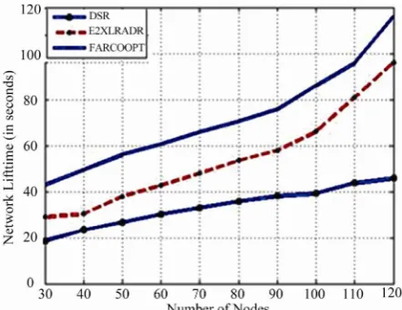
[image:4.595.325.524.588.722.2]Figures 3-5 shows the comparison of 3 different schemes DSR, E2XLRADR, and FARCOOPT method. All the three schemes are build on different strategy.DSR uses traditional multi hop routing; E2XLRADR uses the concept of maximum intermediate node. And FARCOOPT used the concept of best farthest neighbor with coopera-tive transmission. We can observe that with the increase of the node number the lifetime of FARCOOPT increase in comparison to the other schemes. As the rate increases, the lifetime of DSR changes very rapidly because of in-terference, but our FARCOOPT approach can handle
Table 1. Simulation parameters.
Parameters Value
Simulation area 1000 × 1000 m2
Number of nodes 10, ⋅⋅⋅, 250
Transmission range (M) 250
Bandwidth (Mbps) 2
Max node speed (MIS) 10
Tf (Time fixed) 100
Data item size (KB) (1 - 10)
Number of data item 1000
Request interval (S) 10
Simulation time (S) 2000
λe1 3packets/sec
λe2 6packets/sec
Figure 3. Network lifetime of 3 scheme at which node mo-bile rate is 3 packet/sec.
Figure 4. Network lifetime of 3 scheme at which node mo-bile rate is 6 packet/sec.
[image:5.595.311.536.74.267.2]Figure 5. Network lifetime of 3 scheme at which node mo-bile rate is 9 packet/sec.
Figure 6. Increase in the throughput in FARCOOPT.
Figure 7. On increase of number of packet the quality of service increases.
with this situation. Figure 6 talks about the throughput in terms of time. Throughput is not degraded with increase in time of the process. Throughput is measured in bit/Hz which is the unit of frequency efficiency. Figure 7 in-vestigates about the increase in Quality of service even if the number of packets increases.
6. Conclusions
[image:5.595.62.282.77.264.2] [image:5.595.311.536.290.449.2] [image:5.595.61.284.308.483.2] [image:5.595.61.282.523.693.2]throughput of WSN. We have used the cooperative re-transmission when we have to retransmit the data and when during communication link failure occurs. We compared our scheme with traditional approaches like the DSR protocol. By this approach we achieve end to end packet delivery, less loss of data, reliability of net-work, QOS, fairness in service, and energy is also saved to some extent. Several power conservation schemes have been proposed in the literature for prolonging the lifetime of the sensor network, either by trying to reduce the number of retransmission through efficient routing or by taking the advantages of the sleep mode capabilities of the sensor node. Network Performance is also in-creased by FARCOOPT approach.
7. References
[1] K. Lahiri, A. Ragunathan, S. Dey and D. Panigrahi, “Battery-Driven System Design: A New Frontier in Low Power Design,” Proceedings of 7th Asia and South Pa-cific and the 15th International Conference on VLSI De-sign, Bangalore, 7-11 January 2002, pp. 261-267.
[2] V. Kawadia and P. R. Kumar, “A Cautionary Perspective on Cross Layer Design,” IEEE Wireless Communications, Vol. 12, No. 1, 2005, pp. 3-11.
[3] V. Srivastava and M. Motawani, “Cross Layer Design: A Survey and the Road Ahead,” IEEE Communications Magazine,Vol. 43, No. 12, 2006, pp. 112-119.
[4] S. Singh and C. S. Raghavendra, “PAMAS: Power Aware Multi-Access Protocol with Signaling for Ad Hoc Net-works,” ACM Computer Communication Review, Vol. 28,
No. 3, 1998, pp.5-
[5] W. Ye, J. Heidermann and D. Estrin, “An energy Effi-cient MAC Protocol for Wireless Sensor Networks,”
Proceedings of IEEE Infocom, USC/Information Sciences Institute, New York, June 2002, pp. 1567-1576.
[6] W. Heinzelman, A. Chandrakasan and H. Balakrishnan, “Energy Efficient Communication Protocol for Wireless Microsensor Networks,” Proceedings of the Hawaii In-ternational Conference on System Sciences, Washington DC, January 2000, pp. 4-7.
http://www.isi.edu/johnh/PAPERS/Ye02a.html
[7] D. B. Johnson, D. A. Maltz, Y.-C. Hu and J. G. Jetchev, “The Synamic Source for Mobile Ad Hoc Wireless Net-works,” Internet Engineering Task Force Internet Draft, 2000.
[8] C. E. Perkins and E. M. Royer, “Ad Hoc on Demand Distance Vector Routing,” Internet Engineering Task Force Internet Draft, 2003.
http://www.ietf.org/internetdrifts/draft-ietd-manet-adsr-0 6.txt
[9] R. Gunesekaran and H. Qi, “XLRP: Cross Layer Routing Protocol for Wireless Sensor Network,” IEEE Communi-cation Society, Las Vegas, 31 March-3 April 2008, pp. 2135-2140.
http://www.ietf.org/internetdrifts/draft-ietf-manet-aodv-1 3.txt
[10] N. Chilamkurti, S. Zeadally, A. Vasilakos, et al., “Cross Layer Support for Energy Efficient Routing in Wireless Sensor Networks,” Journal of Sensors, Vol. 2009, 2009, pp. 1-9.
[11] Y. B. Bai, S. J. Liu, et al., “An Energy Optimization Proto-col Based on Cross Layer for Wireless Sensor Networks,”
Journal of Communication, Vol. 3, No. 6, 2008, pp. 27-34. doi:10.1155/2009/134165
[12] S. Ni, Y. Tseng, Y. Chen and J. Sheu, “The Broadcast Storm Problem in Mobile Ad Hoc Network,” Wireless Network, Vol. 8, No. 2-3, 2002, pp. 153-167.
[13] P. Skraba, H. K. Aghajan and A. Bahai, “Cross Layer Optimization for High Density Sensor Network: Distri-buted Passive Routing Decisions, Ad Hoc, Mobile, and Wireless Networks,” Proceedings of the Third Interna-tionalConference, ADHOC-NOW, Vancouver, July 2004, pp. 266-279.
[14] T. Aguilar, et al., “A Cross Layer Design Based on Geo-graphic Information for Cooperative Wireless Networks,”
Proceedings of the IEEE 71st Vehicular Technology Conference, Taiwan, 16-19 May 2010, pp. 1-5.
[15] A. Scaglione and Y. W. Hong, “Opportunistic Large Ar-rays: Cooperative Transmission in Wireless Multi Hop Ad Hoc to Reach Far Distances,” IEEE Transaction on Signal Processing, Vol. 51, No. 8, 2003, pp.2082-2092.
[16] A. Scaglione and Y. W. Hong, “Opportunistic Large Ar-rays: Cooperative Transmission in Wireless Multi Hop Ad Hoc to Reach Far Distances,” IEEE Transaction on Signal Processing, Vol. 51, No. 8, 2003, pp.16-20. doi:10.1109/TSP.2003.814519
[17] K. S. Babulal and R. R. Tewari, “E2XLRADR (Energy Efficient Cross Layer Routing Algorithm with Dynamic Retransmission for Wireless Sensor Network”, Interna-tional Journal of Wireless & Mobile Network, Vol 2, No.
3, August 2010, pp.166-177.
[18] K. S. Babulal and R. R. Tewari, “Cross Layer Energy Efficient Routing (XLE2R) for Prolonging Lifetime of Wireless Sensor Networks,” Proceedings of IEEE Interna-tional Conference on Computer and Communication Tech-nology, Allahabad, 17-19 September, 2010, pp. 167-177. [19] K. S. Babulal and R. R. Tewari, “Routing Algorithm: An
Energy Efficient Sleep/Awake Cross Layer for Wireless Sensor Networks”, Advances in Wireless and Mobile Com-munications, Vol. 3, No. 2, 2010, pp. 139–146.
[20] K. S. Babulal, T. R. Ranjan, “Cross Layer RouteDisco-very Using Farthest Intermediate Link Distance Reliabil-ity Cost Based for MANETS,” National Academy of Let-ters, Vol. 34, No. 5-6, 2011.