© 2019, IRJET | Impact Factor value: 7.211 | ISO 9001:2008 Certified Journal
| Page 378
Efficient Reduction of Fault Current in Distribution Systems
Connected With Multiple Distributed Generations
Radha Krishna K.R
1, Dr. T. Ananthapadmanabha
21
Assistant Professor, Department of Electrical & Electronics Engineering, Rajeev Institute of Technology, Hassan,
Karnataka, India
2
Principal, NIE Institute of Technology, Mysuru, Karnataka, India
---***---
ABSTRACT - Connection of distributed generation (DG) to the network and the extension of transmission system with a specific end goal to meet the developing for power are affecting the extent and unpredictability of the system structure. This situation brings about an extensive number of short circuits in the systems, which may cause extreme damage to the system. Introducing Fault current limiters (FCLs) into the power system is a standout amongst the most cost effective approaches to lessen fault current ranges. Likewise islanding operations of DG typically happen when power supply from the fundamental utility is hindered because of a few reasons but the DG continues supplying power into the distribution systems. In this paper, we proposed a novel method for lessening of fault current in distributed system with DGs alongside islanding detection method. In the proposed method, the islanding conditions are detected in light of two parameters they are voltage unbalance and total harmonic distortion of current. Then we design an efficient FCL so as to minimize the impact of the DG on the distribution protection system. At last, so as to locate the optimal location for setting the FCLs in distributed system we formulated the objective function as optimization problem and it is solved by using particle swarm optimization (PSO). The proposed method is implemented on the IEEE bus system and the experimental results are analyzed.
Keywords: Distributed generation (DG), Fault Current Limiter (FCL), Islanding, Particle Swarm Optimization (PSO), distribution system.
1. INTRODUCTION
The DG is in view of the renewable energy sources, for example, energy component, photovoltaic, and wind power, and additionally consolidated heat and power gas turbine, micro turbine, and so on. The number of DG systems is quickly expanding, and the majority of them are associated with a distribution system by supplying power into the system, and in addition neighborhood loads [1]. An islanding operation happens at the point when the DG keeps supplying power into the system after power from the principle utility is intruded [2-3]. In the event that the islanding operation happens, the distribution system gets to be out of the utility's control. It can in this way cause various negative effects on the system and DG itself, for example, the security risks to utility faculty and general society, the power quality issues, and genuine harm to the system and DG unless the fundamental utility power is restored accurately and rapidly. Moreover, the DG system must be detached from the system for its protection by the successful location strategy before the recloser begins to work taking after by the islanding operation [4].
Two types of islanding detection methods, which are the passive and active methods, have so far been developed. The active methods [5], for example, the system fault level checking system and the reactive export error detection technique. In spite of their viability in identifying island operation of DG, these active strategies need to ceaselessly fluctuate the DG output and may adversely influence the operations of the DG and the utility system [6]. Other detection routines can be called passive methods since they recognize islanding operation of DG by observing the system parameters: voltage magnitude, phase displacement, the rate of change in frequency, and impedance checking. Despite the fact that they are unrealistic to impact the working systems and administration of utility power system, if there are little changes in the DG loadings in the wake of islanding, these techniques experience issues in figuring out the islanding operation since the observing parameters don't change enough to recognize these islanding conditions [7].
© 2019, IRJET | Impact Factor value: 7.211 | ISO 9001:2008 Certified Journal
| Page 379
the range of two to three times of the rated current [13]. The impact of such an internal protection needs to be considered in the general system protection plan subsequent to the inverter inward protection can't identify fault streams with levels lower than its settings. There are essentially two sorts of control plans that govern IBDGs, viz., voltage control and current control [14].A few thoughts have been presented as would be prudent solutions [15-16]. These papers propose switchgears and protection coordination update in frameworks comprise of DG. Despite the fact that these arrangements might actually work, they are muddled and expensive. Along these lines, these arrangements are not useful for existing distribution frameworks [17]. Adaptive Relaying calculations were proposed in [18] and [19] to comprehend the detection issues of the IBDGs. In [20], considered the impact on fuse saving plans. While these plans showed promising results, but they are costly solutions obliging additional hardware to be introduced in the system. Besides, the greater part of the previously stated distributions did not examine the impacts on protection plan brought about by different sorts of controllers utilized in IBDGs. Then again, in the few papers that considered the impact of inverter controllers and gave arrangements that are constrained in extent of utilization.
The outline of the paper is organized as follows. Section 2 gives the related researches in impact of multiple DGs. The proposed methodology is given in section 3 and the simulation results and their discussions are given in section 4 followed by conclusion in section 5.
1.1 RELATED WORKS
Vahedi H et al. [21] have presented a new method for islanding detection of inverter-based distributed generation (DG). The main idea of paper was to change the dc-link voltage considering the PCC voltage changes during islanding condition. A simple islanding detection scheme has been designed based on this idea. The proposed method has been studied under multiple-DG operation modes and the UL 1741 islanding tests. The simulations results, carried out by MATLAB/Simulink, show that the proposed method has a small nondetection zone. Also, this method was capable of detecting islanding accurately within the minimum standard time.
Najy W.K.A et al. [22] have proposed a new passive islanding detection method for grid-connected inverter-based distributed-generation (DG) systems. A statistical signal-processing algorithm known as estimation of signal parameters via rotational invariance techniques was used to extract new features from measurements of the voltage and frequency at the point of common coupling as islanding indicators. The new features are defined based on a damped-sinusoid model for power system voltage and frequency waveforms, and include modal initial amplitudes, oscillation frequencies, damping factors, and initial phases. A set of training cases generated on the IEEE 34 us syst m w s us to tr in n v -Bayes classifier that discriminates islanding and nonislanding events. Cross-validation was used to evaluate the performance of the proposed islanding detection method. The results showed that by using the new features extracted from ESPRIT, the classifier was capable of discriminating islanding and nonislanding events with good accuracy.
Sinsukthavorn W et al. [23] have proposed a flexible control methodology of inverters as grid front end using an isochronous control function which is used by synchronous generators in conventional power systems to provide load sharing and control. The control tasks for voltage and frequency are done locally at the inverters to guarantee modularity and to minimize communication requirements. The simulation results illustrated the ability of the proposed concept of inverter control methodology for DG to supply high-quality power. The total load was distributed among the different inverters according to their capacity to guarantee flexibility.
Abdel-Khalik A.S et al. [24] have proposed a solution for IBDG in a medium voltage distribution network that allows active and adjustable IBDG fault current contribution without violating the nonoverload nature of the inverters. This was achieved by introducing a flywheel energy storage system based on a doubly-fed induction machine (DFIM) in parallel with the IBDG. Normally, the flywheel system was dedicated to power leveling; however, during faults, the flywheel DFIM storage system (DFIM) has the ability to supply an exponentially decaying current to the grid. The parallel combination of the IBDG and FW-DFIM as a distributed generation (DG) unit was capable of providing a response similar to that of synchronous generators during a fault, but with additional control capability. The simulated system showed the effectiveness of the DG unit for ownstr m f ults wh r it w s c p l of provi ing suffici nt f ult curr nt to trigg r th istri ution n twork’s prot ction devices when operating in island mode.
© 2019, IRJET | Impact Factor value: 7.211 | ISO 9001:2008 Certified Journal
| Page 380
utilized for calculating the fault current phase angle. The results of the case study simulations proved that IBDGs controlled the fault current magnitude effectively.2. PROPOSED METHODOLOGY TO MITIGATE THE IMPACT OF MULTIPLE DISTRIBUTED GENERATIONS
[image:3.595.111.487.276.324.2]This research work is intended to develop an efficient detection of islanding condition and reduction of fault current produced in distribution system when multiple distributed generations are introduced in the power system. In this work two parameters are used for detecting islanding conditions voltage unbalance and total harmonic distortion of current. Based on this parameters islanding conditions are detected. A fault current limiter is designed in order to minimize the impact of multiple DGs on the protection system in a distribution system during a fault occurrence. Finally, determining the optimal location and impedance of fault current limiter it is modeled as optimization problem with power loss and economical use as objective function. In this work, Particle Swarm Optimization (PSO) algorithm is used for determining the optimal location and impedance of fault current limiter. The outcome of the research produces efficient distribution systems with reduced fault current as well provide protection to the system by islanding detection. The process flow of the proposed system is shown in figure 1.
Islanding Detection System with Multiple
DGs
Optimal Location and Design of Fault Current
Limiter
Figure 1: Process Flow of Proposed System
2.1 ISLANDING DETECTION METHOD
Islanding detection is a one among the most essential issues for the distributed generation (DG) associated with an electric power grid. Islanding condition cause negative effects on protection, operation, and administration of distribution systems; consequently, it is important to effectively distinguish the islanding conditions and quickly detach DG from distribution system. If there are vast changes in loading for DG after loss of the fundamental power supply, then islanding conditions are effortlessly identified by checking a few parameters. In this paper, for detection of islanding operation of DGs, we have used two parameters they are voltage unbalance and total harmonic distortion of the current.
A. Calculation of Voltage Unbalance:
For the most part, despite the fact that the loading for DG has minimal changes after the loss of main source, because of the changes of the systems and the load, the voltage unbalance fluctuates. Along these lines, on the off chance that we continue monitoring the unbalance of three phase output voltage of the DG, at that point it is conceivable to adequately recognize an islanding operation of DG. With a specific end goal to do this, we characterize the voltage unbalance at the observing time by using equation (1) which is given by
100
t t t
PS
NS
VU
(1)Where PStand NSt represents the magnitude of positive and negative sequence of voltage at time t, correspondingly. This characterizes the one sequence average of voltage unbalance which is given in equation (2), furthermore characterizes the voltage unbalance fluctuation which is given in equation (3), which measuring how much the observed voltage unbalance variations from the steady state and ordinary loading conditions.
10 ,
1
Ni i t t
avg
VU
N
VU
(2)100
,,
,
s avg
t avg s
avg t
VU
VU
VU
VU
(3)© 2019, IRJET | Impact Factor value: 7.211 | ISO 9001:2008 Certified Journal
| Page 381
B. Calculation of total harmonic distortion of current:
The changes in the loading for DG due to loss of main power source obviously result in variations on the harmonics of the current. The total harmonic distortion of current at observing time t is given by
100
1 2 2
I
I
THD
H h hWhere
I
his RMS of the harmonic elements h andI
1is RMS value of fundamental element. The average ofTHD
tper cycle is given in equation (5) and the variations for observed THD at time t from the normal condition is given by equation (6).
1 0 ,1
N i i t t avgTHD
N
THD
(5)100
, , ,
s avg t avg s avg tTHD
THD
THD
THD
(6)Where N indicates sampling number per sequence
THD
avg,sindicates reference value for normal loading conditions. Afters avg
THD
, is originally set, if
THD
tremains within -100% through +75% for one cycle,THD
avg,sis updated byTHD
avg,t.C. Detection of islanding condition:
After the calculation of changes in voltage unbalance and total harmonic distortion of current, now we formulate a condition for detection of islanding condition which is given below
50% 100%
% 100 % 75 : t t t t VU or VU THD or THD RULE
If
THD
tand
VU
tsatisfies the above condition the proposed method detects as islanding condition. The flowchart for detection of islanding condition is shown in figure 2.START
Calculate
Satisfy the rule
[image:4.595.147.451.499.737.2]Islanding Condition Detected TRIP STOP Update False True
Figure 2: Flow Chart for Islanding Detection
© 2019, IRJET | Impact Factor value: 7.211 | ISO 9001:2008 Certified Journal
| Page 382
From figure 2, we can see that how islanding condition detected by observing the parameters of voltage unbalance and harmonic distortion of current. Once the islanding mode is detected it gives trip signal and the system is isolated. If it is not detected then the system is analyzed during the occurrence of fault and fault current produced is limited by using fault current limiter which is described in the next section.2.2 FAULT CURRENT LIMITER DESIGN
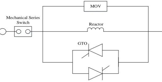
The most beneficial property of this setup is low steady state impedance, straightforwardness of structure and control, high impedance fault and quick response. The structure of fault current limiter is shown in figure 3. It comprises of a solid state switch, voltage limiting element, current limiting impedance, and series mechanical switch.
MOV
Reactor Mechanical Series
Switch
[image:5.595.167.431.216.349.2]GTO
Figure 3: Fault Current Limiter
The GTO thyristors are utilized as the quick solid state switch and current limiting impedance is attached in parallel with thyristors. The GTO thyristors are utilized to interfere with a current immediately after getting a turn off signal and current limiter impedance is utilized as path for passing the fault current when the solid state switch intrude on a shortcoming current. Yet, a sudden intrusion of current is prone to bring about an overvoltage in the circuit, so voltage limiting component is utilized to keep this. The overcurrent detector with the control device detect fault and generate turn on and turn off signals for GTO thyristor.
Most of the system faults are unsymmetrical, balanced three-phase faults are frequently the worst and are utilized to define the Circuit breaker (CB) capacity. For a balanced three-phase fault at bus i, the short circuit current can be computed by
b ii
i sc
i
I
Z
E
I
(7)Where sc i
I
denotes three phase short circuit current at bus i
E
iDenotes voltage before fault at bus i which can be set as 1 p.u
Z
iidenotes thevenin impedance at bus i and it is obtained from diagonal elements of impedance matrixZ
bus.I
bdenotes base current.On adding line with impedance
Z
bbetween buses j and k, original elementZ
xycan be changed as given in below equation
b jk kk jj
ky jy xk xj xy new xy
Z
Z
Z
Z
Z
Z
Z
Z
Z
Z
2
(8)Where new xy
© 2019, IRJET | Impact Factor value: 7.211 | ISO 9001:2008 Certified Journal
| Page 383
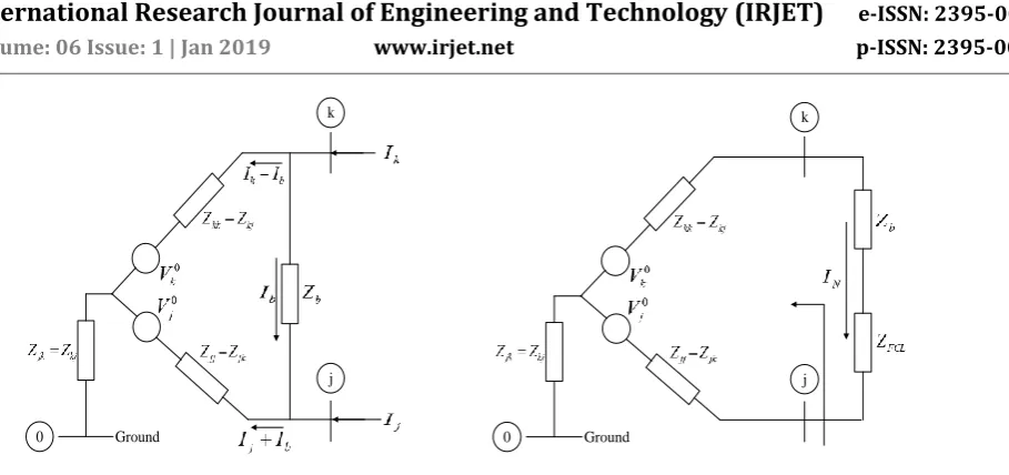
0 j k Ground 0 j k GroundFigure 4: Thevenin equivalent circuit by adding Figure 5: Thevenin equivalent circuit with a line between two existing buses FCL fired up
The total result of inserting
Z
FCLinto the system can be measured as adding a new branch with the following impedance to the system
FCL FCL b b FCL b p pZ
Z
Z
Z
Z
Z
Z
Z
//
(9)Therefore the change to the diagonal entries of
Z
busafter the active FCL fired up at a branch between buses j and k is
p p jk kk ij ik ij iiZ
C
C
Z
Z
Z
Z
Z
Z
Z
1 2 22
(10)The fault current deviation at a bus after the FCL fired up can be written as
ii i ii ii i F i
Z
V
Z
Z
V
I
, (11)Replacing (10) into (11), which can be altered as
1
2,
C
Z
Z
C
Z
V
I
ii p ii i Fi
(12)If the FCL is utilized to constrain the fault current from original
I
i,N toI
i,F, thenZ
prequired can be easily computed by (12) and expressed as1 2 , , ,
C
Z
C
I
I
I
Z
ii F i N i F ip
(13)Replacing (13) into (9), the impedance of active FCL needed is
p b b FCL
Z
Z
Z
Z
© 2019, IRJET | Impact Factor value: 7.211 | ISO 9001:2008 Certified Journal
| Page 384
2.3 LOCATION OF FAULT CURRENT LIMITER
In order to identify the location of fault current limiter we have formulated as nonlinear optimization problem, and different objectives were considered in this study. The objective function consists of minimization of power loss, and economical use of fault current limiter.
2.3.1 Minimization of Power loss:
Optimal placement of FCL can be performed with the reason for minimizing power loss. The aggregate real power loss is computed by using equation (15) which is given as follows:
Nbi
i i
loss
R
I
P
1
2
(15)
Where
R
irepresents resistance of ith branch,I
iis actual current of ith branch, andN
bindicates number of branches in the network.2.3.2 Economical use of FCL:
The total impedance utilized for the fault current limiters should be minimalized to reduce the financial costs [26]. Hence, the problem can be expressed as follows:
L spec f j k N sc j sc f FCL FCL i FCL i FCL i N i FCL i
B
j
k
I
I
B
f
I
I
N
i
Z
Z
Z
t
s
Z
J
FCL,....,
1
,
,...,
1
,...,
1
.
, max , max , , min , 1 ,
(16)where
Z
i,FCLis impedance of ith fault current limiter,N
FCLis the number of installed FCLs, min,FCL i
Z
and max ,FCL iZ
are the minimum and maximum allowed impedance of FCL, scf
I
and sc,max fI
are the fault current at bus f and maximum specified faultcurrent of bus f, f j k
I
, andI
specare the fault current flowing from bus k to j caused by fault at bus f and maximum fault current flowing in the lines.B
NandB
Lare the total number of buses and total number of lines in the system.2.3.3 Formation of objective function:
For the purpose of optimization, the above two mentioned objective function is formulated as follows:
Objective Function,
b FCL N i N i FCL i ii
I
Z
R
Min
F
1 1 , 2 (17)By minimizing the above objective function, we can place or identify the location of FCL to reduce the fault current produced at each bus while distributed generation to the power system. In order to minimize the objective function in our proposed method we have optimization algorithm called Particle Swarm Optimization (PSO).
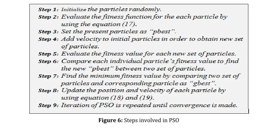
2.3.4 Particle Swarm Optimization (PSO):
© 2019, IRJET | Impact Factor value: 7.211 | ISO 9001:2008 Certified Journal
| Page 385
through the problem space subject to both deterministic and stochastic update rules to new positions, which are subsequently scor . E ch p rticl ptiv ly up t s its v locity n position ccor ing to its own flying xp ri nc n its comp nions’ flying experience, aiming at a better position for itself. As the particles traverse the search space, each particle remember its own personal best position that it has ever visited, and it also knows the best position found by any particle in the swarm. On successive iterations, each particle takes the path of a damped oscillatory movement towards its personal best and the global best positions. With the oscillation and stochastic adjustment, particles explore regions throughout the problem space and eventually settle down near a good solution. Th lgorithm st rts y initi lizing popul tion of p rticl s in th “norm liz ” search space with random positions x and random velocities v, which are constrained between zero and one in each dimension. A particle position vector is converted into a candidate solution vector in the problem space through a mapping. Here equation (17) is regarded as the fitness of the corresponding particle. Updating the position and velocity of particles is performed by using below equations.
k
i i k
i i k
i k
i
wv
c
rand
pbest
u
c
rand
gbest
u
v
1
1 1
2 2
(18) 1
1
ki k i k
i
u
v
u
(19) Where ki
v
is velocity of agent i at iteration kw is weighting function
1
c
andc
2are the relative weights of the personal best position and global best position, respectivelyrand is random number between 0 and 1
k i
u
is current position of agent i at iteration ki
pbest
is pbest of particle ii
gbest
is gbest of the groupThe weighting function can be calculated by using the below formula
iter
iter
w
w
w
m ax m in m ax
(20)
[image:8.595.66.530.558.773.2]Where
w
maxandw
minare the maximum and minimum weight,iter
maxanditer
are maximum and current iteration number. The steps involved in PSO algorithm is shown below:© 2019, IRJET | Impact Factor value: 7.211 | ISO 9001:2008 Certified Journal
| Page 386
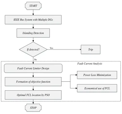
The overall process of the proposed method is shown in the flowchart which can be seen in figure 7.IEEE Bus System with Multiple DGs
If detected? Islanding Detection
Trip START
Fault Current Limiter Design
Formation of objective function
Power Loss Minimization
Economical use of FCL
Optimal FCL location by PSO
STOP
Fault Current Analysis
Yes
[image:9.595.100.496.110.481.2]No
Figure 7: Flowchart of Overall Proposed Method
From the flowchart given in figure 7, we can clearly understood the concept of the proposed method, initially an IEEE bus system with multiple DGs is considered, then the system is detected for islanding condition if detected means the trip signal is given to the circuit and the system is isolated. Then, the fault current limiter is designed and optimally placed in order to reduce the fault currents produced by DGs. The simulation results of the proposed method is given in next section.
3. SIMULATION RESULTS AND DISCUSSION
In this paper we have proposed a method for detection of islanding condition and placement of fault current limiter is done by using particle swarm optimization in a distribution system connected with multiple distributed generations.
System Configuration:
Operating System: Windows 8 Processor: Intel Core i3 RAM: 4 GB
© 2019, IRJET | Impact Factor value: 7.211 | ISO 9001:2008 Certified Journal
| Page 387
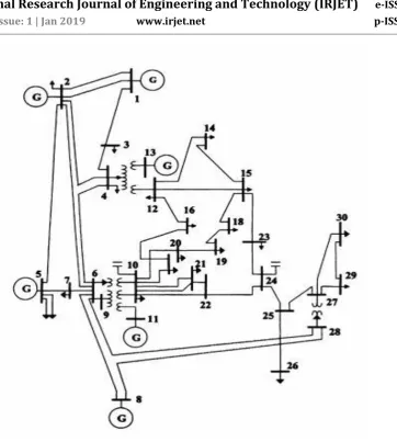
Figure 8: IEEE 30 bus System
To test the proposed method for islanding detection we have made a typical islanding condition of the DG connected at Bus 5 in figure 8 by opening the circuit breaker at the time 83ms between Bus 7 and 6. The magnitude of voltage before introducing islanding condition is shown in figure 9. After introducing islanding there is a large variation in DG loadings, as shown in Figure 10, there is a sudden change in the line to line voltage at the time 83ms. So, the islanding operation condition is easily and rapidly detected by voltage parameter.
[image:10.595.113.487.556.728.2]© 2019, IRJET | Impact Factor value: 7.211 | ISO 9001:2008 Certified Journal
| Page 388
Figure 10: Result for islanding operation with large variation in DG loading in Voltage magnitude.
Similarly, the variation in total harmonic distortion of current is shown in figure 11. However, unlike other parameters, the changes in the THD of the current and voltage unbalance are large enough to detect the islanding operation.
Figure 11: Result for islanding operation with THD of current
[image:11.595.99.496.397.642.2]© 2019, IRJET | Impact Factor value: 7.211 | ISO 9001:2008 Certified Journal
| Page 389
Figure 12: Fitness Graph of PSO
The optimal solutions obtained for this case are as follows:
An FCL with an impedance of 3.0187 ohms should be installed on line 23.
An FCL with an impedance of 2.3187 ohms should be installed on line 25.
An FCL with an impedance of 0.0094 ohms should be installed on line 12.
[image:12.595.59.534.500.601.2]The short-circuit currents at buses 12 and 21 after FCLs installations are reduced to 1.0234 kA and 1.5623 kA, respectively. Note that only three FCLs are required to suppress fault currents at three buses. Using the proposed PSO technique to solve the optimization problem, we can see that numbers of fault current limiter required are less compared with other techniques. After introducing the fault current limiter the total power loss reduced to 2.1021 kW. In order to prove the effectiveness of our proposed method, we make a comparison with other techniques like Genetic algorithm, Evolutionary Programming which is shown in table 1.
Table 1: Performance Comparison
Methods Number of FCL
FCL
Z
(total) Total Power LossEvolutionary Programming (EP) 5 6.125 ohms 2.7852 kW
Genetic Algorithm (GA) 4 5.9814 ohms 2.4982 kW
Proposed Method 3 5.3468 ohms 2.1021 kW
From table 1, we can see that our proposed has achieved minimum power loss with less number of fault current limiters compared with other techniques. From this, we can say that our proposed method is best method for optimal placement of fault current limiters in the distribution system.
4. CONCLUSION
© 2019, IRJET | Impact Factor value: 7.211 | ISO 9001:2008 Certified Journal
| Page 390
method. PSO is utilized to locate the minimum number of FCLs and select the conceivable littlest circuit parameters of FCLs to guarantee that bus fault currents are inside CB ratings.REFERENCES
[1] Fun shi T, Koy n gi K, n Yokoy m R, “A r vi w of isl n ing t ction m tho s for istri ut r sourc s” In Proceedings of IEEE International Conference on Power Tech Conference, vol. 2, 2003.
[2] De Mango F, Liserre M, Aquila A.D, and Pigazo A, "Overview of Anti-Islanding Algorithms for PV Systems. Part I: Passive Methods", In proceedings of IEEE International conference on Power Electronics and Motion Control Conference (EPE-PEMC), pp. 1878-1883, 2006.
[3] De Mango F, Liserre M, and Aquila A.D, "Overview of Anti-Islanding Algorithms for PV Systems. Part II: Active Methods", In proceedings of IEEE International conference on Power Electronics and Motion Control Conference (EPE-PEMC), pp. 1884-1889, 2006.
[4] Zeineldin H.H, "A Q–f Droop Curve for Facilitating Islanding Detection of Inverter-Based Distributed Generation", IEEE Transactions on Power Electronics, vol. 24, no. 3, pp. 665-673, 2009.
[5] Mahat P, Chen Z, and Bak-J ns n B, “R vi w of isl n ing t ction m tho s for istri ut g n r tion” In Proc ings of IEEE International conference on Electric Utility Deregulation and Restructuring and Power Technologies (DRPT), pp. 2743-2748, 2008.
[6] Xu W, Zh ng G, Li C, W ng W, W ng G, n Kli r, J, “A pow r lin sign ling s t chniqu for nti-islanding protection of distributed generators—p rt i: sch m n n lysis”, IEEE Tr ns ctions on Pow r D liv ry, vol. 22, no. 3, pp. 1758-1766, 2007.
[7] Zeineldin H. H, n Kirtl y J. L, “A simpl t chniqu for isl n ing t ction with n gligi l non t ction zon ”, IEEE Transactions on Power Delivery, vol. 24, no. 2, pp. 779-786, 2009.
[8] Mozina C.J, "Impact of Green Power Distributed Generation", IEEE Industry Applications Magazine, vol. 16, no. 4, pp. 55-62, 2010.
[9] Abdel-Khalik A.S, Elserougi A.A, Massoud A.M, and Ahmed S, "Fault Current Contribution of Medium Voltage Inverter and Doubly-Fed Induction-Machine-Based Flywheel Energy Storage System", IEEE Transactions on Sustainable Energy, vol. 4, no. 1, pp. 58-67, 2013.
[10] Nimpitiwan N, Heydt G.T, Ayyanar R, and Suryanarayanan S, "Fault Current Contribution From Synchronous Machine and Inverter Based Distributed Generators", IEEE Transactions on Power Delivery, vol. 22, no. 1, pp. 634-641, 2007.
[11] Yi Han, Xuehao Hu, and Dongxia Zhang, "Study of adaptive fault current algorithm for microgrid dominated by inverter based distributed generators", In Proceedings of IEEE International Symposium on Power Electronics for Distributed Generation Systems (PEDG), pp. 852-854, 2010.
[12] Mozina C.J, "Impact of green power generation on distribution systems in a smart grid", In Proceedings of IEEE International Conference on Power Systems Conference and Exposition (PSCE), pp. 1-8, 2011.
[13] Loix T, Wijnhoven T, and Deconinck G, "Protection of microgrids with a high penetration of inverter-coupled energy sources", In Proceedings of IEEE International Symposium on Integration of Wide-Scale Renewable Resources Into the Power Delivery System, pp. 1-6, 2009.
[14] Baran M.E, and El-Markaby I, "Fault analysis on distribution feeders with distributed generators," IEEE Transactions on Power Systems, vol. 20, no. 4, pp. 1757-1764, 2005.
[15] Brahma S.M, and Girgis A.A, "Development of adaptive protection scheme for distribution systems with high penetration of distributed generation", IEEE Transactions on Power Delivery, vol. 19, no. 1, pp. 56-63, 2004.
© 2019, IRJET | Impact Factor value: 7.211 | ISO 9001:2008 Certified Journal
| Page 391
[17] Shahriari S.A.A, Abapour M, Yazdian A, and Haghifam M-R, "Minimizing the impact of distributed generation on distribution protection system by solid state fault current limiter", IN Proceedings of IEEE International Conference on Transmission and Distribution Conference and Exposition, pp. 1-7, 2010.[18] Hui Wan, Li K.K, and Wong K.P, "An Adaptive Multiagent Approach to Protection Relay Coordination With Distributed Generators in Industrial Power Distribution System", IEEE Transactions on Industry Applications, vol. 46, no. 5, pp. 2118-2124, 2010.
[19] Mahat P, Zhe Chen, Bak-Jensen B, and Bak C.L, "A Simple Adaptive Overcurrent Protection of Distribution Systems with Distributed Generation", IEEE Transactions on Smart Grid, vol. 2, no. 3, pp. 428-437, 2011.
[20] Yazdanpanahi H, Yun Wei Li, and Wilsun Xu, "A New Control Strategy to Mitigate the Impact of Inverter-Based DGs on Protection System", IEEE Transactions on Smart Grid, vol. 3, no. 3, pp. 1427-1436, 2012.
[21] Vahedi H, Noroozian R, Jalilvand A, and Gharehpetian G.B, "A New Method for Islanding Detection of Inverter-Based Distributed Generation Using DC-Link Voltage Control", IEEE Transactions on Power Delivery, vol. 26, no. 2, pp. 1176-1186, 2011.
[22] Najy W.K.A, Zeineldin H.H, Alaboudy A.H.K, and Wei Lee Woon, "A Bayesian Passive Islanding Detection Method for Inverter-Based Distributed Generation Using ESPRIT", IEEE Transactions on Power Delivery, vol. 26, no. 4, pp. 2687-2696, 2011.
[23] Sinsukthavorn W, Ortjohann E, Mohd A, Hamsic N, and Morton D, "Control Strategy for Three-/Four-Wire-Inverter-Based Distributed Generation", IEEE Transactions on Industrial Electronics, vol. 59, no. 10, pp. 3890-3899, 2012.
[24] Abdel-Khalik A.S, Elserougi A.A, Massoud A.M, and Ahmed S, "Fault Current Contribution of Medium Voltage Inverter and Doubly-Fed Induction-Machine-Based Flywheel Energy Storage System", IEEE Transactions on Sustainable Energy, vol. 4, no. 1, pp. 58-67, 2013.
[25] Rajaei N, Ahmed M.H, Salama M.M.A, and Varma R.K, "Fault Current Management Using Inverter-Based Distributed Generators in Smart Grids", IEEE Transactions on Smart Grid, vol. 5, no. 5, pp. 2183-2193, 2014.
[26] ZARE S, Khazali A, HASHEMI S. M, KHALILI R, CO-Iran T. B. T. B, and UNI-Ir n I. U. S. T, “F ult Curr nt Limit r Optim l Pl c m nt y H rmony S rch Algorithm”, In Proc ings of IET International conference on Electricity Distribution, pp. 1-4, 2013.
[27] W ng C, n N hrir M. H, “An lytic l ppro ch s for optim l pl c m nt of istri ut g n r tion sourc s in pow r syst ms”, IEEE Tr ns ctions on Pow r Syst ms, vol. 19, no. 4, pp. 2068-2076, 2004.
BIOGRAPHIES
Radhakrishna K.R joined as lecturer in EEE department, Adichunchanagiri Institute of Technology chikmagaluru in the year 2000 and served the institution for 8 years and then he joined S.I.E.T Tumkur in 2009 as a Lecturer and served the institution for one year and presently he is working as Asst professor,EEE Department in Rajeev Institute of Technology, Hassan from 2009 to till Date. He is life member of ISTE, and Member of Institute of Engineers. He is Pursuing Ph.D. in VTU under the guidance of Dr.T.Ananthapadmanabha, Principal, NIEIT, Mysuru