Intensity-based image registration using multiple
distributed agents
TAIT, Roger J., SCHAEFER, Gerald and HOPGOOD, Adrian A.
Available from Sheffield Hallam University Research Archive (SHURA) at:
http://shura.shu.ac.uk/5646/
This document is the author deposited version. You are advised to consult the
publisher's version if you wish to cite from it.
Published version
TAIT, Roger J., SCHAEFER, Gerald and HOPGOOD, Adrian A. (2008).
Intensity-based image registration using multiple distributed agents. Knowledge-Based
Systems, 21 (3), 256-264.
Copyright and re-use policy
See
http://shura.shu.ac.uk/information.html
Intensity-Based Image Registration
Using Multiple Distributed Agents
Roger J. Tait*, Gerald Schaefer† and Adrian A. Hopgood** *
School of Computing and Informatics, Nottingham Trent University, Clifton Lane, Nottingham, NG11 8NS, UK
†
School of Engineering and Applied Science, Aston University, Aston Triangle, Birmingham, B4 7ET, UK
**
Faculty of Computing Sciences & Engineering, De Montfort University, The Gateway, Leicester, LE1 9BH, UK
Tel. +44 (0)115 848 8403; Email: [email protected] Tel. +44 (0)121 204 3470; Email: [email protected]
Tel. +44 (0)116 257 7092; Email: [email protected]
Abstract
Registration is the process of geometrically aligning two images taken from different sensors, viewpoints or instances in time. It plays a key role in the detection of defects or anomalies for automated visual inspection. A multiagent distributed blackboard system has been developed for intensity-based image registration. The images are divided into segments and allocated to individual agents on separate processors, allowing parallel computation of a similarity metric that measures the degree of likeness between reference and sensed images after the application of a transform. The need for a dedicated control module is removed by coordination of Distributor, Manager, and Worker agents through communication via the blackboard. Tests show that the system achieves large-scale registration with substantial speedups, provided the communication capacity of the blackboard is not saturated. The success of the approach is demonstrated in the detection of manufacturing defects on screen-printed plastic bottles and printed circuit boards.
1
Introduction
In fields as diverse as manufacturing and medicine, there is an increasing need for automated visual inspection in the detection of defects or anomalies. The main motivating factors for the adoption of an automated approach include reliability, reproducibility, reduction of labour costs, and speed. In a manufacturing context, increased speed holds the potential for inspection rates matched to high-speed production.
Many of the visual inspection methods reviewed in the literature employ image registration to align geometrically data taken from different sensors, viewpoints or instances in time [3]. During registration, fixed and moving images are aligned through a combination of translation, rotation, and scaling [4]. A universal registration technique is not possible due to the wide variety of noise and geometric deformations within captured data. Often these distortions are caused by the diverse methods of imaging available. Currently, registration is classified as either feature- or intensity-based, where both techniques have their own advantages and disadvantages.
Feature-based registration [5] is only as accurate as the initial selection of landmarks. In contrast, intensity-based registration methods [6] use all data within an image. Additional masking can be introduced to emphasise special features. The basic intensity approach consists of transform optimisation, image re-sampling and feature-matching stages. Feature matching is the most fundamental stage and is achieved through the use of a similarity metric [7], in which a degree of likeness between corresponding images is calculated. Both in practical and research terms, iterative computation of the similarity metric represents a considerable performance bottleneck that limits the speed of a visual inspection system. The flexibility of the inspection process is also limited by the inability to select between computational strategies for similarity based on their relative strengths, such as insensitivity to noise or possession of a large capture range [8].
The distributed multiagent framework presented in this paper achieves high-performance intensity-based image registration, which is a significant step in addressing the limitations of visual inspection. The innovative approach supports multiple distributed agents organised in a Worker/Manager model [9]. Agent interaction and cooperation is achieved through the blackboard architecture, which has emerged from its 1970s origins as a modern, practical means of managing agent cooperation towards a common goal [10]. The original blackboard architecture was envisaged as a coordinated and distributed problem-solving environment that could be used to combine multiple processing techniques [11]. Advances in networking and agent-based technologies mean that this vision is now a reality. In the current work, rapid image registration is achieved, without recourse to expensive hardware, by sharing the computational task among separate agents that can run on any networked computer.
2
The Blackboard Architecture
A blackboard system is analogous to a team of experts who communicate their ideas via a physical blackboard, by adding or deleting items in response to the information that they find there. The experts were originally represented by specialist modules known as knowledge sources but, in a modern blackboard system, they are replaced by independent autonomous agents with specialized areas of knowledge.
strategy for its particular task, e.g., backward- or forward-chaining, and can be thought of as a knowledge-based system in microcosm [10].
Since the emergence of the first blackboard architectures, most notably the Hearsay-II speech understanding system [12], a variety of frameworks have been employed in the inspection field. ARBS (Algorithmic and Rule-based Blackboard System) combined rules, algorithms, and neural networks for the interpretation of ultrasonic images [13]. More recently, artificial neural networks embedded in a different rule-based blackboard system have been employed to identify erosion in steel bridge structures [14]. Both of these examples are non-distributed architectures comprising three main components: the blackboard module, the agents, and a control or scheduler module.
DARBS (Distributed ARBS) [15, 16] is a distributed blackboard system based on a client/server model. The server functions as the blackboard while agents are implemented as client modules. The distributed nature of the implementation means that both blackboard and client modules run as separate processes and that no controller or scheduler is required. These independent processes may reside on a single processor or on any TCP/IP networked computers. Reading from and writing to the blackboard is implemented as standard functionality and provides a mechanism for communication between all agents. Storage of working data on the blackboard ensures equal access for all active agents.
Worker N agent Distributor agent Manager agent
Blackboard
[image:4.595.221.376.380.489.2]Worker 1 agent
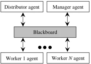
Fig 1 Worker/Manager model for the multiagent framework. The Distributor agent segments the image, Worker agents perform concurrent processing of the segments, and the Manager agent coordinates Worker agent activities.
3
Distributed Image Registration
Fig 1 shows that the image registration framework consists of Distributor, Manager, and N Worker agents. For an agent to be part of the framework it must first establish connection with the blackboard over the network. Framework initialisation and image selection are performed by the Distributor agent. The Distributor agent then splits fixed and moving images into segments before placing them on the blackboard. Worker agents take image segments from the blackboard and calculate local gradients using a global transform [17]. The Manager agent then updates the global transform based on local gradients, while coordinating Worker agent activities. Calculation of local gradients and updating of the global transform is repeated until predefined thresholds are exceeded. Finally, a resulting image is constructed from registered segments.
performance can be expected with a single-partition implementation. Similar inefficiency can be expected when an agent requests information through management and processing of excess partitions. To combat these problems the chosen partition scheme allows interaction between agents in a logical and efficient manner. DARBS’s unique ability to create, manipulate, and destroy partitions during run time overcomes the limitations of less dynamic blackboard implementations. The partitioning of data also aids design of the multiagent framework by introducing structure to an area of shared memory. This simplifies creation of agent rule files as the number of partitions with which an agent works is kept to a minimum.
As shown in Fig 2, the blackboard is initially divided into seven partitions. Image data are transmitted to and from the blackboard by the agents. Transmission data are divided into three parts: segment identification number, segment size, and pixel data.
Blackboard
Worker agent Manager agent
Distributor control
Fixed
Worker control Manager control
Moving Processed
Parameters
[image:5.595.156.443.311.427.2]Distributor agent
Fig 2 Blackboard partitions used for logical storage and efficient retrieval of data. Arrows indicate the specific partitions accessed by the individual agents.
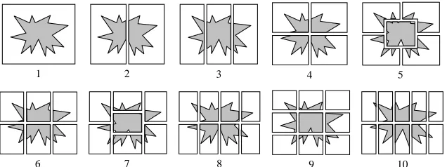
A distribution scheme was chosen whereby full resolution images are divided into a variable number of segments, each containing approximately the same number of pixels. Fig 3 shows how an image is split up into any number of segments between two and ten. This maximises the possibility of detail appearing in all segments and evenly distributes the workload between processors. The distribution scheme also benefits from the fact that no inter-processor communication is required. Duplication methods were not considered due to their transmission overheads.
10 9
8 7
6
1 2 3 4 5
[image:5.595.140.458.552.671.2]In a sequential registration process, a similarity metric is used to compute the degree of likeness between fixed and moving images after the application of a transform. To distribute similarity computation, two new correlation-based metrics have been developed for the registration framework. They are adaptations of metrics implemented as part of the ITK toolkit [18]. Mutual Information metrics, described elsewhere [19], can also be implemented in the framework. During evaluation of a transform, for each pixel coordinate in the fixed segment, a corresponding coordinate in the moving segment is calculated. By repeating the process within predefined regions of interest and summing intensities from a gradient image for all valid pixel coordinates, local gradients are calculated by Worker agents. The chosen interpolation scheme is used to compute non-discrete pixel coordinates. Accumulation and summation of local gradients by the Manager agent allows for computation of either mean-squares (MS) or normalised-correlation (NC) similarity metrics between fixed (A) and moving (B) images. In the ITK implementations, MS and NS are defined as
(
)
∑
= − = p N i i i p B A N 1 2 1MS (1)
(
)
∑
∑
∑
= = =−
=
p p p N i i N i i N i i iB
A
B
A
1 2 1 2 1NC
(2)where Ai and Bi are gradients at the ith pixel coordinates and Np is the number of
valid pixels considered. A pixel coordinate is thought valid if it maps to a position within the boundaries of the moving image. The new, more efficient, distributed version of these metrics, implemented as part of the registration framework, are
(
)
∑
∑ ∑
= = =
−
=
S i i S i P j i j i jP
B
A
i 1 1 1 2MS
(3)∑
∑
∑
∑ ∑
= = = = =
−
=
S i P j i j P j i j S i P j i j i j i i iB
A
B
A
1 1 2 1 2 1 1NC
(4)where Aij and Bij are gradients at the jth pixel coordinates of segment i from image
A and B respectively, Pi is the number of valid pixel between segments identified
4
Agent Implementation
Worker and Manager agents are provided with image registration functionality through the embedding of shared library algorithms in rule files. An intensity-based algorithm suited to images of the same modality forms the basis of this functionality. The algorithm can be tailored, via the blackboard, to a specific problem with dynamically selectable components. The components consist of transform, interpolation and optimiser types. Both translation-only and centred-affine transform types are available to perform a spatial mapping between fixed and moving segments. In order to evaluate non-discrete pixel coordinates, linear and b-spline interpolation schemes are provided. A gradient-descent optimiser is used to search iteratively for the transform that best satisfies the chosen metric.
4.1Distributor agent
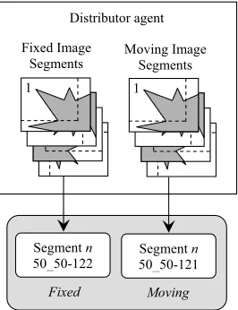
The Distributor agent consists of four rule files. Tasks performed by Initalise_Distributor include clearance of all data from the blackboard. The Select_Images rule causes the appearance of a user interface consisting of a simple image viewer and Open File dialog box. On image selection, the user interface is automatically closed. Moments calculated from the selected images are used to estimate centres of mass. The vector that joins both centres is used as an initial transform and added to the Parameters partition. These actions form part of the Set_Transform rule. On firing of Store_Segments, the images are divided into segments and sent to the blackboard. A region of interest is also generated for each segment and again added the blackboard. The region of interest is designed to create a border at the edges of a segment.
As illustrated in Fig 4, only edges that face neighbouring segments have a border. The border is intended to remove non-pixel values that enter at the edges of a segment, due to translation and rotation during registration. Although the size of border is variable, the setting of a wide border will cause a decrease in efficiency as additional redundant data will be accrued and processed.
Distributor agent
1 Fixed Image
Segments
1
Moving Image Segments
Moving Fixed
Segment n
50_50-122
Segment n
[image:7.595.232.365.488.661.2]50_50-121
Fig 4 The Distributor agent divides an image into segments and places them in the
4.2Worker agent
A Worker agent comprises five rule files. Connection to the blackboard and initialisation of a Worker agent are performed by the Initalise_Worker rule. On firing of Fetch_Segments, both fixed and moving segments with a corresponding region of interest are retrieved from the blackboard. The Worker agent then enters a loop, by means of Wait_Worker, where it waits for a transform to appear in its
control partition.
Fig 5 shows addition and retrieval of data from the blackboard by a Worker agent. As soon as a transform appears, it is removed. This stops the Worker agent from repeatedly firing the Perform_Optimisation rule. On firing of Perform_Optimisation, a local gradient between fixed and moving segments is calculated by the registration module using the fetched transform. Once calculated, the number of valid pixel coordinates and local gradient are placed in the Worker’s
control partition. The process is repeated each time an updated transform appears in the Worker agent’s control partition. When a final transform appears, the Resample_Segment rule is fired, causing translation and rotation of the moving segment using final transform parameters and return of the registered segment to the blackboard.
Workern agent
Transform 1_0_0_1_4.2
Gradient 2.7182374
Pixels 34555 Transform
1_0_0_1_4.2
Gradient 2.7182374
Worker n control Fixed
Moving
Pixels 34555 Segment n
50_50-121
n
Segment n
[image:8.595.215.381.360.550.2]50_50-122
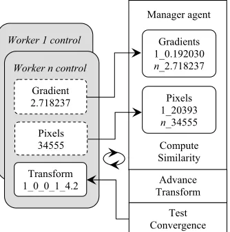
Fig 5 The Worker n agent iteratively collects transform parameters and calculates gradient and pixels data.
4.3Manager agent
Addition and retrieval of data from the blackboard by the Manager agent are shown in Fig 6. A similarity measure is calculated using the total number of valid pixel coordinates and local gradients, on firing of Advance_Transform. The similarity measure is used to calculate an updated transform. A convergence test is then carried out that considers the updated transform’s length, the magnitude of similarity measure and number of iterations performed. In the event of these parameters exceeding a predefined threshold, the updated transform is replaced with a final transform. Otherwise, the updated transform is propagated to all
Worker control partitions and the process is repeated.
Reconstruct_Image is fired on appearance of the final transform. This rule causes registered segments to be retrieved from the blackboard. Each registered segment then has its borders removed before being inserted into a resulting image. The resulting image is automatically displayed by means of an image viewer.
Worker 1 control
Transform 1_0_0_1_4.2
Worker n control
Manager agent
Compute Similarity
Test Convergence
Advance Transform
Gradients 1_0.192030
n_2.718237
Pixels 1_20393
n_34555 Gradient
2.718237
[image:9.595.216.383.301.470.2]Pixels 34555
Fig 6 The Manager agent collects gradient and pixel data, which it uses to compute similarity, update transform parameters, and test if convergence of the registration process has been reached.
4.4Interaction between agents
As each agent adds to an iterative process, a control scheme was needed to coordinate contributions. Most blackboard implementations achieve coordination by the inclusion of a dedicated control module to activate specific agents. In the registration framework described here, preconditions are attached to agent rule files. These preconditions determine, in accordance with information on the blackboard, when an agent can make its contribution at any given time. This reactive behaviour removes the need for a dedicated control module and related overheads.
these items are also removed from the blackboard. A corrupt path through transform search space would occur if both Manager and Worker agents operated with parameters from different iterations.
Blackboard
Worker 1 agent
Gradient & Pixels
Transform
Workern agent
Gradient & Pixels
Manager agent Gradients & Pixels
[image:10.595.164.430.186.275.2]Transform
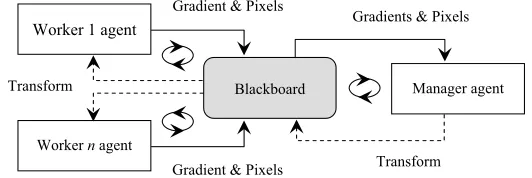
Fig 7 Flow of gradient data and updated transform parameters between agents. Once updated by the Manager, transform parameters are propagated to all Worker agents.
5
Experimental Results
Registration into a common coordinate system requires iterative computation of a similarity metric before any referential comparison by an inspection system can be made. Accuracy of the registration process is also wholly dependent upon the selection of appropriate transform, interpolation and optimisation types. Components selected to perform testing of MS and NC metrics were therefore based on a priori knowledge. The following components were chosen:
• a centred-affine transform that allows rotation, scaling, shearing, and translation of image segments;
• b-spline interpolation in order to achieve greater accuracy than linear interpolation;
• a regular step gradient descent optimiser because of its compatibility with other components.
In order to evaluate the increased performance of the registration framework, quantitative evidence of its advantages over an alternative method currently in use was required. A sequential algorithm, provided by the ITK toolkit, was updated with the same components and used as a benchmark for comparison.
Ultimately, the choice of resolution will determine the smallest size of detectable defect. Therefore large images, containing screen-printed bottle logos of approximately 1400×1800 pixels, were chosen as test samples. The fixed image represented a sample with an acceptable and verified quality of manufacture. In contrast, the moving images contained samples with a variety of defects. These included screen leak and missing print, both of which can be caused by incorrect ink viscosity, material contamination or tool wear. Subtraction before testing revealed that an unknown translation and rotation between fixed and moving images existed. In all cases, once selected, images were divided by the Distributor agent into segments and a 10-pixel wide border was assigned.
subtracting the thresholded fixed segment from the registered segment. Finally, noise is removed from the difference image using morphological opening [21]. This process results in an opened segment which is returned to the blackboard in place of the registered segment.
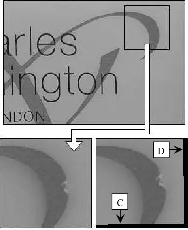
An example of a fixed reference image, the corresponding moving image data, and a resulting registered segment after alignment by a Worker agent is shown in Fig 8. An area of missing print is clearly visible in the moving and registered segments. Translation and rotation caused by the alignment process has introduced non-pixel locations which are visible at the bottom (C) and right-hand sides (D) of the registered segment. These extraneous pixels are removed by the Manager agent when it constructs the resulting image.
D
[image:11.595.201.395.279.516.2]C
Fig 8 Fixed, moving and registered image data. An area of missing print is clearly visible in the moving and registered segments.
E
[image:12.595.198.399.145.238.2]F G
Fig 9 Referential comparison of the fixed and registered segments reveals a screen-printing defect.
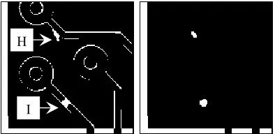
To demonstrate the flexibility of the registration framework, printed circuit board [22] images were also tested. Fig 10 shows how samples containing artificially introduced defects can also be successfully registered and segmented by the framework. A spur (H) and an open circuit (I) have been detected. These are typical manufacturing defects that can be caused by dirt on the preprinted board or by air bubbles from electrolysis.
H
[image:12.595.200.397.347.443.2]I
Fig 10 Referential comparison of the fixed and registered segments reveals printed circuit board defects.
Performance testing of the image registration framework was carried out in a computer laboratory with personal computers interconnected by an Ethernet 100Mbps switch. All computers in the network contained AMD Athlon 1.67GHz processors with 224 megabytes of random access memory and were running the Debian Sarge Linux operating system. During testing, the number of Worker agents was equal to the number of segments. Distribution of the framework also represented the ideal case, i.e. one processor for the blackboard and one processor for each agent. Each algorithm was applied to four images and the average processing time calculated. On convergence of the registration process, the number of iterations and final transform parameters were compared with the sequential implementation.
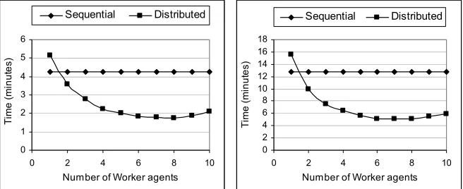
Figs 11(a) and 11(b) illustrate the sequential execution time and distributed speedup achieved during registration of bottle images with the MS and NC similarity metrics respectively. It can be seen that, in each case, the distribution of image data among seven Worker agents reduces the execution time by approximately 60% compared with sequential processing. The performance diminishes as the number of processors is increased beyond seven.
parameters that matched those computed by the sequential algorithm. This correspondence of parameters indicates that the path through transform search space followed was the same for sequential and distributed implementations. Thus, the framework achieves increased performance when compared to an existing implementation. The reduced processing time of the MS metric, compared with the NC implementation, is caused by its shorter path through transform search space. The shorter path and hence fewer iterations is reflected in the timescale of Fig 11.
0 2 4 6 8 10 12 14 16 18
0 2 4 6 8 10
Number of Worker agents
T
im
e
(
m
in
u
te
s
)
Sequential Distributed
0 1 2 3 4 5 6
0 2 4 6 8 10
Number of Worker agents
T
ime
(mi
n
u
te
s
)
[image:13.595.134.462.231.365.2]Sequential Distributed
Fig 11 Sequential and distributed similarity metric performance with increasing numbers of Worker agents: (a) MS metric, (b) NC metric.
Mean-squares (MS) Normalised-correlation (NC) Registration
parameters: Sequential Distributed Sequential Distributed
Iterations 19 19 31 31
Translation in x 13.806 13.806 13.681 13.681 Translation in y 10.945 10.945 10.657 10.657 Rotation centre x 665.707 665.707 665.799 665.799 Rotation centre y 896.997 896.997 896.983 896.983
Angle 9.95° 9.95° 9.898° 9.898°
Table 1 Registration parameters after convergence.
6
Discussion
Efficiency of the framework is reduced by an initial overloading of communications caused by Worker agents that try to obtain segments from the blackboard when first triggered. A second overload occurs when Worker agents have finished processing and try to return registered segments to their respective partitions. This synchronisation occurs when Worker agents operate in a first-come first-served fashion, particularly in situations when the number of segments is high. Creation of a schedule, prior to commencement of the Worker agents, represents a static load-balancing approach that could be adopted. Similarly, compression of transmission data should increase communication efficiency. The goal of any such approaches will be to distribute communications better and to reduce the idle time of Worker agents.
7
Conclusions
High image resolutions, coupled with complex algorithms, have increased the demand for greater performance capabilities in the automated visual inspection field. Based on a worker/manager model and implemented using a distributed blackboard architecture, an innovative framework has been presented that achieves high-performance intensity-based image registration for use in referential comparison. Data partitioning and distribution, followed by dynamic algorithm selection and computation of either MS or NC similarity metric, are achieved with specialised agents that work in parallel. Defect detection on screen-printed bottles and printed circuit boards has demonstrated the effectiveness of the approach.
The performed tests show that parallel calculation of the similarity metric, which is seen as the major performance bottleneck associated with intensity-based registration, results in significant speedup compared with a non-distributed implementation. The approach described is cost-effective and can be easily expanded by the addition of agents and processors, unlike schemes with specialised hardware, such as shared-memory and multiprocessor environments. Other similarity computation strategies can be added as specialised agents, without changes to the framework.
For future work, it is intended that additional flexibility will be added to the framework in the form of metrics that are suited to images of differing modalities [23] and volumetric data [24]. Because some metrics need to be initialised with near optimal transform parameters while others have larger capture ranges, the selection of an appropriate metric for an inspection application will be dependent on the registration problem in hand.
Acknowledgement
The authors are grateful to M&H Plastics Ltd for the supply of the screen-printed bottles showing known defects.
References
1. T.S. Newman and A.K. Jain, A survey of automated visual inspection, Computer Vision and Image Understanding 61 (1995) 231-62.
3. B. Zitova and J. Flusser, Image registration methods: a survey, Image and Vision Computing 21 (2003) 977-1000.
4. L.G. Brown, A survey of image registration techniques, ACM Computing Surveys (1992) 325-376.
5. B. Temkin, S. Vaidyanath and E. Acosta, A high accuracy, landmark-based, sub-pixel level image registration method, International Congress Series 1281 (2005) 254-259. 6. K. Jeongtae and J.A. Fessler, Intensity-based Image Registration using Robust
Correlation Coefficients, IEEE Transactions on Medical Imaging 23 (2004) 1430-1444. 7. G.P. Penney, J. Weese, J.A. Little, P. Desmedt, D.L.G. Hill and D.J.A. Hawkes,
Comparison of similarity measures for use in 2D-3D medical image registration, IEEE Transactions on Medical Imaging 17 (1998) 586-95.
8. J. Zhang and A. Rangarajan, Affine image registration using a new information metric, IEEE Computer Society Conference on Computer Vision and Pattern Recognition (CVPR’04) (2004) 848-855.
9. R. Murch and J. Johanson, Intelligent Software Agents, Prentice Hall, USA (1998). 10. A.A. Hopgood, The state of artificial intelligence, Advances in Computers 65 (2005)
1-75.
11. H.P. Nii, Blackboard systems: the blackboard model of problem solving and the evolution of blackboard architectures, AI Magazine 7 (1986) 38-53.
12. L.D. Erman, F. Hayes-Roth, V.R. Lesser and D.R. Reddy, The Hearsay-II speech understanding system: integrating knowledge to resolve uncertainty, ACM Computing Surveys 12 (1980) 213-253.
13. A.A. Hopgood, N. Woodcock, N.J. Hallam and P.D. Picton, Interpreting ultrasonic images using rules, algorithms and neural networks, European Journal of Non-Destructive Testing 2 (1993) 135-149.
14. S.V. Barai and P.C. Pandey, Integration of damage assessment paradigms of steel bridges on a blackboard architecture, Expert Systems with Applications, 19 (2000) 193-207.
15. L. Nolle, K.C.P. Wong and A.A. Hopgood, DARBS: a distributed blackboard system, Research and Development in Intelligent Systems XVIII, M. Bramer, F. Coenen and A. Preece (eds.) (2001) 161-70.
16. K.W. Choy, A.A. Hopgood, L. Nolle and B.C. O'Neill, Implementation of a tileworld testbed on a distributed blackboard system, 18th European Simulation Multiconference (2004) 129-135.
17. R.J. Tait, G. Schaefer and A.A. Hopgood, Towards high performance image registration using intelligent agents, 13th International Conference on Systems, Signals and Image Processing (IWSSIP), Budapest, Hungary (2006).
18. NLM. Insight segmentation and registration toolkit, http://www.itk.org (2004).
19. R.J. Tait, G. Schaefer, K. Howell, A.A. Hopgood, P. Woo, and J. Harper, Automated overlay of visual and thermal medical images, Int. Biosignal Conf. (2006).
20. N. Otsu, A threshold selection method from gray-level histograms, IEEE Transactions on Systems Man and Cybernetics (1979) 62-66.
21. S. Umbaugh, Computer Vision and Image Processing, Prentice Hall USA (1998). 22. M. Moganti, F. Ercal, C. Dagli and S. Tsunekawa, Automatic PCB inspection
algorithms: a survey, Computer Vision and Image Understanding 63 (1996) 287-313. 23. C. Nikou, F. Heitz and J. Armspach, Robust voxel similarity metric for the registration
of dissimilar single and multimodal images, Pattern Recognition 32 (1999) 1351-1368. 24. W. Wells, P. Viola, H. Atsumi, S. Nakajima and R. Kikinis, Multi-modal volume