©IJRASET: All Rights are Reserved
179
Stability Improvement of Multi-Machine Power
System Network using STATCOM & UPFC
Sandeep Kumar1, Dr. Deependra Singh2, Dr. K. S. Verma3 1
M.Tech Scholar,Department of Electrical Engineering, Kamla Nehru Institute of Technology, Sultanpur, U.P, India
2, 3
Professor, Department of Electrical Engineering, Kamla Nehru Institute of Technology, Sultanpur, U.P, India
Abstract: Recent power system transmission networks are becoming with increasing complexity due to growing demand and restrictions on building new lines. Loss of stability is one of the major problem of such a modern power system following a disturbance. Transient stability control is an important concept which ensuring the stable operation of power system during the fault and large disturbances. FACTS technologies are raise to be very effective in a power system transmission network for better controllability and increase power transfer capability without sacrificing the desired stability margin. This paper provides the comparative performance of STSTCOM, SVC and UPFC for improvement of transient stability of IEEE 9 bus power system. Static Synchronous Compensator and Static Var Compensator are the shunt devices of the Flexible AC Transmission Systems (FACTS) family.
When the system voltage is low, STATCOM generates reactive power and when the system voltage is high then it absorbs reactive power whereas SVC is also operates as same as the STATCOM. SVC provides the fast acting dynamic compensation in case of severe fault. The UPFC is more effective Flexible AC Transmission Systems (FACTS) device for controlling active and reactive power flow in a transmission line and power oscillation damping by controlling its series and shunt parameters. To analyzing the effects of STATCOM, UPFC and SVC on transient stability performance of the system by using the MATLAB/Simulink environment for multi- machine system. The performance of STATCOM, SVC and UPFC are compared with each other.
The simulation results will show the effective and robustness of all the three FACTS devices. Higher degree Flexible AC Transmission Systems (FACTS) device can be identified by this project for transient stability of IEEE 9 bus power system. Keywords: FACTS, STATCOM, SVC and UPFC, Transient Stability and IEEE 9 bus power system.
I. INTRODUCTION
Power system generally consist of three stages: such as generation, transmission, and distribution. The First stage is generation, the electric power is generated generally by using synchronous generators. Then the voltage range is increased by transformers before the power is transmitted in order to decrease the line currents which consequently reduce the power transmission losses. After the transmission, the voltage is stepped down using transformers in order to be distributed accordingly. Power systems are planned to provide uninterrupted power supply that hold voltage stability.
However, due to undesired events, such as lightning, accidents or any other uncertain events, short circuits between the phase conductors of the transmission lines or between a phase conductor and the ground which may occur is called a fault. Due to occurring of a fault, one or more generators may be severely disturbed causing an instability between generation and demand. If the fault persists and is not cleared in a pre-specified time frame, it may cause strong damages to the equipment’s which in turn may lead to a power loss and power outage.
Hence, antifouling equipment’s are compartment to observe faults and clear/separate faulted parts of the power system as quickly as possible in front the fault energy is pass on to the rest of the system.
MATLAB Simulink is an interactional environment for modelling and simulating a wide variety of dynamic systems. A system is built easily using blocks and results can be displayed quickly. Simulink is used for perusing the effects of non-linearity of the system and thus is an ideal research tool.
©IJRASET: All Rights are Reserved
180
II. POWER SYSTEM STABILITY
Electrical Power system stability is the ability of an electric power system, for a given initial operating condition, to retrieve a state of operating equilibrium after being subjected to a physical disturbance, with most system variables bounded so that practically the entire system remains intact. Stability phenomenon is a single problem associated with various forms of instabilities affected on power system due to the high dimensionality and complexity of power system constructions and behaviors. For properly understood of stability, the classification is essential for significant power system stability analysis. Stability classified based on the nature of resulting system instability (voltage instability, frequency instability), the size of the disturbance (small disturbance, large disturbance) and time frame of stability (short term, long term). In the other hand, stability broadly classified as steady state stability and dynamic stability. Steady state stability is the ability of the system to transit from one operating point to another under the condition of small load changes. Power system dynamic stability appears in the literature as a class of rotor angle stability to describe whether the system can maintain the stable operation after various disturbances or not.
A. Transient Stability
Whenever a power system is under steady state, the load and transmission loss equals to the generation in the system. The generating units run at synchronous speed and system frequency, voltage, current and power flows are steady. When a large disturbance such as three phase fault, loss of load, loss of generation etc., occurs the power balance is upset and the generating units rotors experience either acceleration or deceleration. The system may come back to a steady state condition maintaining synchronism or it may break into subsystems or one or more machines may pull out of synchronism. In the previous case the system is said to be stable and in the later case it is said to be unstable.
III. FACTS CONTROLLERS
FACTS are defined by the IEEE as “a power electronic based system and other static equipment that provide control of one or more AC transmission system parameters to enhance controllability and increase power transfer capability”. Basically, FACTS controllers can be divided into four categories:
1)Series Controller
2)Shunt Controller
3)Combined series-series Controller
[image:2.612.145.469.480.624.2]4)Combined series-shunt Controller
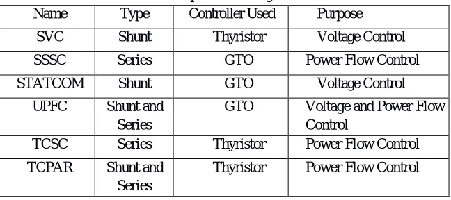
Table 1. Comparison among FACTS Controllers Name Type Controller Used Purpose
SVC Shunt Thyristor Voltage Control
SSSC Series GTO Power Flow Control
STATCOM Shunt GTO Voltage Control
UPFC Shunt and Series
GTO Voltage and Power Flow Control
TCSC Series Thyristor Power Flow Control
TCPAR Shunt and Series
Thyristor Power Flow Control
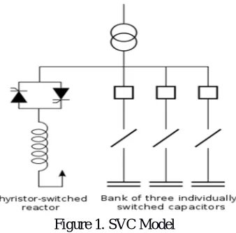
A. Static VAR Compensator (SVC)
Static VAR Compensator (SVC) provides the fast reactive power on high voltage transmission networks. An SVC is based on
©IJRASET: All Rights are Reserved
181
Figure 1. SVC Model
Static VAR Compensator (SVC) had a great advantage over simple mechanically-switched compensation schemes is their fast instantaneous response to changes in the system voltage. For this reason they are often operated at close to their zero-point in order to maximize the reactive power correction they can rapidly provide in system whenever required. They are in general cheaper, higher- capacity, faster, efficient and more reliable over dynamic compensation schemes such as synchronous condensers.
B. Static Synchronous Compensator (STATCOM)
STATCOM is a shunt-connected static Var compensator whose capacitive or inductive output current can be controlled independently of the ac system voltage. STATCOM is made up of a coupling transformer, a VSC and a dc energy storage device as shown in fig2. STATCOM is capable of exchanging reactive power with the transmission line
Figure 2. STATCOM Model
C. Unified Power Flow Controller (UPFC)
The Unified Power Flow Controller (UPFC) is the most versatile FACTS controller developed so far, with all-encompassing
©IJRASET: All Rights are Reserved
182
Figure 3. UPFC Model
D. Power System Stabilizers
PSS have been extensively used as supplementary excitation controllers to damp out the low frequency oscillations and enhance the overall system stability. Fixed structure stabilizers have practical applications and generally provide acceptable dynamic performance. There have been arguments that these controllers, being tuned for one nominal operating condition, provide sub optimal performance when there are variations in the system load. There are two main approaches to stabilize a power system over a wide range of operating
[image:4.612.179.434.352.417.2]Conditions, namely robust control. The block diagram for the designed conventional PSS is shown in Fig.4
Figure 4. Power System Stabilizer Model
IV. SIMULATION MODEL AND RESULTS
A. IEEE 9-bus power system installed with P
[image:4.612.215.434.475.719.2]©IJRASET: All Rights are Reserved
183
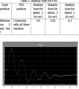
Table 2. Stability chart for PSS Fault
position
PSS position
Stability time for delta1_2 (in sec)
Stability time for delta2_3 (in sec)
Stability time for delta3_1 (in sec) Between
bus 5 and bus 7
Connected with all three machine
[image:5.612.175.443.80.381.2]3.9 3.65 4.3
[image:5.612.184.439.409.551.2]Figure 5.1Rotor angle deviation between machine M1 and M2
Figure 5.2. Rotor angle deviation between machine M2 and M3
[image:5.612.183.440.582.708.2]©IJRASET: All Rights are Reserved
184
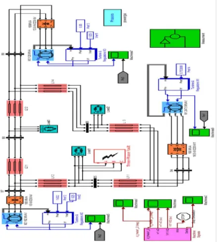
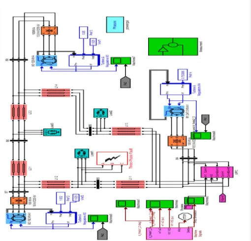
B. IEEE 9-bus power system installed with STATCOM and PSS
[image:6.612.205.422.95.389.2]Figure 6. Simulink model of three machine 9-busbar network with PSS and STATCOM
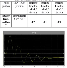
Table 3. Stability chart for STATCOM Fault
position
STATCOM position
Stability time for delta1_2 (in sec)
Stability time for delta2_3 (in sec)
Stability time for delta3_1 (in sec) Between
bus 5 and bus
7
Between bus 4 and bus 5
4.2 4.1 4.3
[image:6.612.167.444.435.715.2]©IJRASET: All Rights are Reserved
185
[image:7.612.178.433.472.717.2]Figure 6.2. Rotor angle deviation between machine M2 and M1
Figure 6.3. Rotor angle deviation between machine M3 and M1
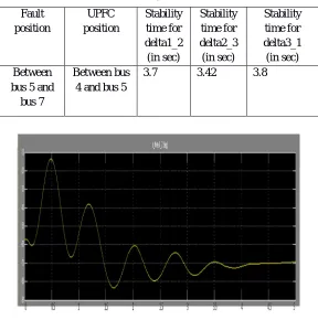
C. IEEE 9-bus Power System Installed with UPFC and PSS
©IJRASET: All Rights are Reserved
186
[image:8.612.179.434.406.537.2]Table 4. Stability chart for UPFC
[image:8.612.180.433.570.713.2]Figure 7.1. Rotor angle deviation between machine M1 and M2
Figure 7.2. Rotor angle deviation between machine M2 and M1
Figure 7.3. Rotor angle deviation between machine M3 and M1 Fault
position
UPFC position
Stability time for delta1_2 (in sec)
Stability time for delta2_3 (in sec)
Stability time for delta3_1 (in sec) Between
bus 5 and bus 7
Between bus 4 and bus 5
©IJRASET: All Rights are Reserved
187
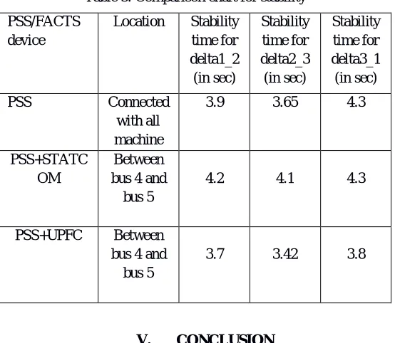
Table 5. Comparison chart for stability
V. CONCLUSION
The power system stability has been compared and discussed for improvement of a 3-machine 9 bus system by PSS, STATCOM & UPFC. After simulation results shown in Fig, a comparison is made between the above FACTS devices for stability enhancement of IEEE 9 bus system as shown in Table-5. From the Table-5, it is inferred that UPFC is the effective FACT device for stability enhancement over STATCOM and PSS as the post settling time obtained from the use of UPFC is less as compared to that obtained from STATCOM and PSS.
REFERENCES
[1] Dr. Raja Singh Khela and Sandeep kaur, “Transient Stability Using FACTS Controller”, IJLTET, Volume 7, Issue 1, May 2016.
[2] Shenglong Yu, Tat Kei Chau, and Tyrone Fernando, Andrey V. Savkin, and Herbert H.-C. Iu, “Novel Quasi- Decentralized SMC-Based Frequency and Voltage Stability Enhancement Strategies using Valve Position Control and FACTS Device”, IEEE Access, May 2016.
[3] Bhuvan Sharma Arvind Sharma, “Power System Stability Enhancement Using FACTS”, IJARCSSE, Volume 5, Issue 5, May 2015.
[4] Tingjian Liu, Youbo Liu, and Junyong Liu, Yue Yang, Gareth A. Taylor, and Zhengwen Huang, “Multi- indicator Inference Scheme for Fuzzy Assessment of Power System Transient Stability”, IEEE, Volume 2, Issue 3, September 2016.
[5] Yang Liu, Q. H. Wu, and Haotian Kang, Xiaoxin Zhou, “Switching Power System Stabilizer and Its Coordination for Enhancement of Multi-machine Power System Stability”, IEEE, Volume 2, Issue 2, June 2016
[6] Divya Prakash, Er. Vinay Kumar, “Enhancing Stability of Multi-Machine IEEE 9 Bus Power System Network Using PSS”, IJAREEIE, Volume 4, Issue 5, May 2015
[7] Ben-Sheng Chen and Yuan-Yih Hsu, “An Analytical Approach to Harmonic Analysis and Controller Design of a STATCOM”, IEEE, Volume 22, Issue 1, January 2007
[8] Siwei Liu, Gengyin Li, and Ming Zhou, “Power System Transient Stability Analysis with Integration of DFIGs Based on Center of Inertia” IEEE, Volume 2, Issue 2, June 2016
[9] P. Kundar, “Power System Stability and Control”. NewYork: McGraw-Hill, 1994.
[10] Swaroop Kumar.Nallagalva,Mukesh Kumar Kirar, and Dr.Ganga Agnihotri, “Transient Stability Analysis of the IEEE 9-Bus Electric Power System” IJSET, Volume 1, Issue 3, July 2012.
[11] S.K.Sethy, J.K.Moharana, “Design, Analysis and Simulation of Linear Model of a STATCOM for Reactive Power Compensation with Variation of DC- link Voltage” IJEIT, Volume 2, Issue 5, November 2012.
[12] Prof. P.S.R. Murthy, “Power System Analysis”, Hyderabad: BS Publications, 2007.
[13] M. Srinivasa Rao, L. Murali Mohan, “Transient Stability Performance Analysis of Power System Using Facts Devices” IJERA, Volume 4, Issue 2, February 2014.
[14] Sanjiv Kumar, Dr. Narendra Kumar, “Effectiveness of FACTS Devices for Power System Stability Enhancement” IJAES, Volume 1, Issue 2, April 2011. [15] P R Sharma, Narender Hooda, “Transient Stability Analysis of Power System Using Matlab” IJESRT, Volume 1, Issue 7, September 2012.
[16] Hingorani, N. G., &Gyugyi, L. (2000). Understanding FACTS: concepts and technology of flexible AC transmission systems (Vol. 1). M. El-Hawary (Ed.). New York: IEEE press.
[17] Murali, D., Rajaram, D. M., &Reka, N. (2010). Comparison of FACTS devices for power system stability enhancement. International Journal of Computer Applications (0975–8887) Volume, 30-35.
[18] Deshpande, A. S., Kadam, P. A. and Rana, V. M. (2011, May). First Swing Stability of Power System Using FACTS Device. 2011 National Conference on Recent trends in Engineering and Technology.
PSS/FACTS device
Location Stability time for delta1_2 (in sec) Stability time for delta2_3 (in sec) Stability time for delta3_1 (in sec)
PSS Connected with all machine
3.9 3.65 4.3
PSS+STATC OM
Between bus 4 and bus 5
4.2 4.1 4.3
PSS+UPFC Between bus 4 and bus 5
©IJRASET: All Rights are Reserved
188
[19] Rath, S., Sahu B., & Dash, P. (2012). Power System Operation and Control Using FACTS Devices. International Journal of Engineering Research and Technology. 1(5).
[20] Murali, D., &Rajaram, M. (2010). Active and Reactive Power Flow Control using FACTS Devices. International Journal of Computer Applications. 9(8). 45-50.
[21] Kumar, A., &Priya, G. (2012, December). Power system stability enhancement using FACTS controllers. In Emerging Trends in Electrical Engineering and Energy Management (ICETEEEM), 2012 International Conference on (pp. 84-87). IEEE.
[22] Kodsi, S. M., &Canizares, C. A. (2003). Modeling and simulation of IEEE 14 bus system with FACTS controllers. University of Waterloo, Canada, Tech. Rep. [23] Haddad, S., Haddouche, A. &Bouyeda, H. (2009, April). The use of FACTS Devices in Distributed power systems-Modelling, Interface and case
study.International Journal of Computer and Electrical Engineering. 1(1).
[24] Abido, M. A. (2009). POWER SYSTEM STABILITY ENHANCEMENT USING FACTS CONTROLLERS: A REVIEW. Arabian Journal for Science & Engineering (Springer Science & Business Media BV),34.
[25] Somalwar, R. &Khemaria, M. (2012, March). A Review of enhancement of Transient stability using FACTS Devices. International journal of Emerging Technologies in Sciences and Engineering, 5(3).
[26] Mohanty, A. K., &Barik, A. K. (2011). Power System Stability Improvement Using FACTS Devices. International Journal of Modern Engineering Research, 1(2), 666-672
[27] ABAZARI, & EMADI. (2003). Transient stability improvement by using advanced static VAR compensators. Electric Power Components and Systems, 31(4), 321-334