Vibrant Performance of Power Oscillation
Damping Controller by E-STATCOM
Sathya Prathap1, B.Rambabu2, D.Mahesh Kumar3, Dr. B. Ramesh Babu4
M.Tech, Dept. of EEE, ALITS, Affiliated to JNTUA, AP, India1
Associate Professor, Dept. of EEE, ALITS, Affiliated to JNTUA, AP, India2
Associate Professor, Dept. of EEE, ALITS, Affiliated to JNTUA, AP, India3
Principal, ALITS, Affiliated to JNTUA, AP, India4
ABSTRACT: This paper describes an approach to design a damping controller of a energy storage type STATCOM (E-STATCOM). The energy storage type STATCOM is an advanced flexible AC transmission system (FACTS) device, which controls both active and reactive power injection/absorption to the power system. It also provides a better power swing damping. Using a linearized block diagram proposed by the author, the present study examines the design of the E-STATCOM damping controller. Several case studies have been performed to evaluate the power swing damping effect of the ESTATCOM a machine infinite bus system. The effectiveness of the proposed control method to provide power oscillation damping irrespective of the connection point of the device and in the presence of system parameter uncertainties will be verified through simulation results.
KEYWORDS: Power system stability, Flexible ac transmission system (FACTS), Static synchronous compensator (STATCOM), Energy storage, Linearized model.
I. INTRODUCTION
These nonlinear controllers have good performance if the system model is accurate and the parameters are precisely obtained. The shortcoming is that the robustness is not guaranteed in the presence of modelling inaccuracies. i.e. Parameter uncertainty and un-modelled dynamics, especially in feedback linearization (FL) method.
II. INTEGRATION OF BATTERY ENERGY STORAGE WITH A STATCOM
The static synchronous compensator or statcom is a shunt-connected device. The statcom does not employ capacitor or reactor banks to produce reactive power as does the Static Variable Compensator (SVC). In the StatCom, the capacitor bank is used to maintain a constant DC voltage for the voltage-source converter operation. Common Statcom may vary from six-pulse topologies up to forty-eight-pulse topologies that consist of eight six-pulse converters operated from a common dc link capacitor. The displacement angle between two consecutive six-pulse converters in a multi pulse converter configuration is where the total number of six-pulse converters is. The configuration of an integrated Statcom/ESS is shown in Fig: 1 Phase adjustments between the 6-pulse converter groups are accomplished by the use of appropriate magnetic circuits. Using this topology, the angle of the statcom voltage can be varied with respect to the AC system voltage. By controlling the angle, the Statcom can inject capacitive or inductive current at the AC system bus. Although the ability of a Statcom to improve power system performance has been well accepted, very little information regarding its dynamic control has been published. The Statcom is best suited for voltage control since it may rapidly inject or absorb reactive power to stabilize voltage.
Fig: 1.Integrated Statcom with energy storage
III. POD CONTROLLER DESIGN
Considering the simplified two-machine system in Fig: 2, the active power output from each generator should change in proportion to the change in its speed to provide damping. It can be observed that the effect of the power injected by the compensator on the generator active power output highly depends on the parameter α, i.e., on the location of the E -STATCOM. Using the equivalent system, a control input signal that contains information on the speed variation of the generators can be derived. When the E-STATCOM is not injecting any current, the variation of the locally measured signals, Өg and Ptran and at different E-STATCOM connection points using the dynamic generator rotor angles δg1and
δg2 is given by
Өg = δg2 + tan
From a small-signal point of view and under the assumption that the PCC-voltage magnitude along the line Eg does not
change significantly, the required control input signals can be derived from the PCC-voltage phase and transmitted active power as
Where Ѓpis a constant (transmitted active power). The nominal system frequency is represented by wg0 whereas ∆wg1
and ∆wg2 represent the speed variation of the generators in p.u. The electromechanical dynamics for each generator is
given by
Where Hgi , ∆wgi , ∆Tmi , ∆Tgi , and KDmi represent inertia constant, speed variation, change in input torque, change in
output torque and mechanical damping constant for the ith generator, respectively. The derivative of the PCC-voltage phase and transmitted active power are both dependent on the speed variation of the generators. Moreover, the derivative of the PCC-voltage phase depends on the location of E-STATCOM, through the parameter, as well as the mechanical dynamics of the generators as shown in above equation. This information will be exploited in the POD controller design. For the two machine system in Fig: 2, damping is related to the variation of the speed difference between the two generators, ∆wg12= ∆wg1-∆wg2. It can be understood that the change in the output power from the generators due to injected active power is maximum when the compensator is installed at the generator terminals. Assuming equal inertia constant for the two generators, no damping is provided by injection of active.
IV. ESTIMATION OF CONTROL INPUT SIGNALS
To describe the estimation algorithm, an input signal which could be either wg or Ptran, as shown in Fig: 2, is
Fig: 2 Block diagram of the POD controller.
Therefore, the input signal consists of an average component Yavg and an oscillatory component Yosc which can be modelled as
Where Yosc is expressed in terms of its amplitude (Yph), frequency (wosc)and phase (φ) and it can be rewritten as
From the observation matrix and measured input signal y(t), the estimated state vector ĥ is derived using RLS algorithm in discrete time as
Calling the I identity matrix, the gain matrix G and covariance Matrix R are calculated recursively starting with an initial invertible matrix R(0) as:
Where λ represents the forgetting factor for the RLS algorithm such that 0< λ <1 . With Ts representing the sampling time, the steady-state bandwidth of the RLS αRLS and the estimation error is given by:
V. STABILITY ANALYSIS OF SYSTEM MODEL
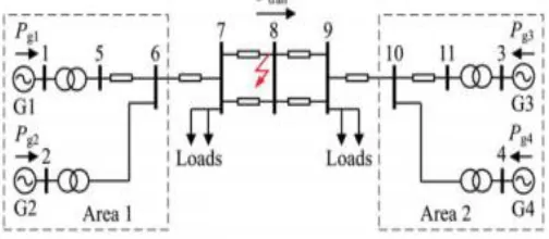
The POD controller described in this section is verified by using the well-known two area four machine system as shown in Fig: 3.
As it is seen in these figures, voltage angles are controlled in order to damp oscillations and variations of voltage magnitudes are rather small. This clearly shows that inter-area oscillations have close relationship with active power flow changes throughout the network. Fig: 4 Without POD controller and Fig: 5 Shows injected active powers by E-STATCOMs. As it is seen, E-STATCOMs need to inject multiple orders of their nominal active powers in a short period of time and this in turn causes dc capacitors to be discharged temporarily.
VI. SIMULATION RESULTS
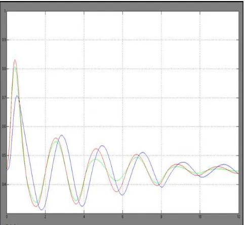
(A) E-STATCOM CONNECTED AT BUS7
(B)E-STATCOM CONNECTED AT BUS 8
(C) E-STATCOM CONNECTED AT BUS 9
Fig 5: Measured transmitted active power output following a three-phase fault with E-STATCOM connected at bus 7 (A), bus 8 (B), and bus 9 (C)
VII. CONCLUSION
POD controller by E-STATCOM has been produced in this paper. For this, a changed RLS calculation has been utilized for estimation of the low-recurrence electromechanical motions segments from privately measured signs amid force framework unsettling influences. The dynamic execution of the POD controller to give compelling damping at different association purposes of the E-STATCOM has been approved through reproduction and additionally test check.
REFERENCES
[1] N.G.Hingorani and L.G yugyi “understanding FACTS. Concepts and Technology of Flexible AC Transmission System. New York, NY,USA:IEEE,2000
[2] G.Cao,Z.Y.Dong,,Y.Wang, P.Zhang,and Y.TOh, “VSC Based STATCOM Controller for Damping Multimode Oscillations,” in Proc. IEEE Power and
EnergySoc. General Meeting-Conversion and Delivery of Electrical Energy in the 21st Century, jul.2008,PP.1-8
[3] M. Zarghami and M.L Crow, “Damping Inter-area Oscillations n Power Systems by STATCOMS,” in Proc. 40th North Amer. Power Symp, Sep.2008,PP.1-6.
[4] Z.Yang, C.Shen, L.Zhang, M.L.Crow, and S.Atcitty, “Integration of A STATCOM and Energy Storage,” IEEE Trains. Power Syst., Vol.16, No.2, PP.254-260, May 2001
[5] A. Arulamplam, J.B Ekanayake, and N.Jenkins, “Applications Study of A Study of A STATCOM with Energy Storage,” Proc. Inst. Eletr. Eng.-Gener., Transm .andDistrib., Vol.150,PP. 373-384, July 2003.
[6] N. Wade, P. Taylor, P. Lang, and J. Svensson, “Energy Storage foe Power Flow Management and Voltage Control on an
11 KV UK Distribution Network,” Prague, Czech Republic, CIRED paper 0824, Jun.2009.
[7] A. Adamczyk, R.Teodorescu, and P.Rodriguez, “Control of Full-Scale Converter Based Wind Power Plants for Damping of low Frequency System Oscillations,” in Proc. IEEE Power Tech, Trondheim, Norway, Jun.2011,PP.1-7
BIOGRAPHY
P.SATHYAPRATHAP, completed My B.Tech (E.E.E.) in Gokula Krishna College Of Engineering , Sullurupet(Nellor Dist) And Now Pursuing My M.Tech (E.P.S.) In Anantha Lakshmi Institute of Technology and Sciences, Anantapuram.
B.RAMBABU, completed My B.Tech (E.E.E.) in K.S.R.M.COLLEGE OF ENGG, KADAPA, A.P. ,and M.TECH(H.V.Engg.),in J.N.T.U.K, KAKINADA, currently working as Associate Professor in Anantha Lakshmi Institute of Technology and Sciences, Anantapuram
D.MAHESH KUMAR, M.TECH (Ph.D.) Associate Professor in Anantha Lakshmi Institute of Technology and Sciences, Anantapuram