(SOFCS) BASED ON LA- AND CA-DOPED SRTIO
₃
Lanying Lu
A Thesis Submitted for the Degree of PhD at the
University of St Andrews
2015
Full metadata for this item is available in St Andrews Research Repository
at:
http://research-repository.st-andrews.ac.uk/
Please use this identifier to cite or link to this item:
http://hdl.handle.net/10023/7068
This item is protected by original copyright
Studies of Anode Supported Solid Oxide Fuel Cells
(SOFCs) Based on La- and Ca-Doped SrTiO
3Lanying Lu
This thesis is submitted in partial fulfilment for the degree of PhD
at the
University of St Andrews
I
I, Lanying Lu, hereby certify that this thesis, which is approximately 52,000 words in length, has been written by me, and that it is the record of work carried out by me, or principally by myself in collaboration with others as acknowledged, and that it has not been submitted in any previous application for a higher degree.
I was admitted as a research student in October 2011 and as a candidate for the degree of Doctor of Philosophy in October 2014; the higher study for which this is a record was carried out in the University of St Andrews between 2011 and 2014.
Date …… signature of candidate ………
I hereby certify that the candidate has fulfilled the conditions of the Resolution and Regulations appropriate for the degree of Doctor of Philosophy in the University of St Andrews and that the candidate is qualified to submit this thesis in application for that degree.
Date …… signature of supervisor………
Date …… signature of supervisor ………
In submitting this thesis to the University of St Andrews I understand that I am giving permission for it to be made available for use in accordance with the regulations of the University Library for the time being in force, subject to any copyright vested in the work not being affected thereby. I also understand that the title and the abstract will be published, and that a copy of the work may be made and supplied to any bona fide library or research worker, that my thesis will be electronically accessible for personal or research use unless exempt by award of an embargo as requested below, and that the library has the right to migrate my thesis into new electronic forms as required to ensure continued access to the thesis. I have obtained any third-party copyright permissions that may be required in order to allow such access and migration, or have requested the appropriate embargo below.
The following is an agreed request by candidate and supervisors regarding the publication of this thesis:
Access to printed copy but embargo on electronic copy for a period of 2 years on the following ground:
Publication would preclude future publication.
Date …… signature of candidate ……
Date …… signature of supervisor ………
II
First and foremost, I would like to sincerely thank my supervisors, Prof. John Irvine and Dr. Mark Cassidy, for giving me the opportunity to work as a PhD student in the research filed of solid oxide fuel cells. My knowledge and experience on solid oxide fuel cells were quite minimal before I started this project, but they have been always patient to me and responded to my queries associated with the laboratory work and data analysis very promptly. Their support, trust and profound knowledge are definitely the most essential factors for the completion of my thesis. Without their involvement, I would never be capable of finishing my thesis.
I would like to thank all the members of the JTSI group for the help with testing instruments and result discussion during my three years in St Andrews. In particular, I want to show my deep gratitude to Dr. Maarten Verbraeken for teaching me the slurry preparation and tape casting technique, Dr. David Miller for the TEM and EDX analysis on my samples and Dr. Mark Cassidy for the kind help on screen printing technique. I also acknowledge Mrs. Julie Nairn and Dr. Paul Conner who helped me a lot in the lab, Mrs Sylvia Williamson who taught me to operate TGA and dilatometer, and Mr. Ross Blackley for the demonstration of SEM equipments.
My deepest gratitude goes to Mr. Alan Davidson in Napier University, Edinburgh for his supervision and guidance on the work about Ni-YSZ anode fabrication using the electroless Ni-YSZ co-deposition process. Special thanks to Dr Callum Wilson, Dr. Neil Shearer and Mr. Dong Wang for the lab-related work and discussion.
My thanks also to MCS company, Edinburgh that collaborated with my research. Mr. Stewart McCracken, Dr. Andrew Gibson and Dr. Stephen Mee have helped me to slot my samples for FIB preparation even when the cutting system was extremely busy and spared their time for my manuscript correction.
I would like to grant my special thanks to my family for all the help and support throughout my study. Although being far away, my parents have encouraged me to pursue my PhD study all the time. To my husband, Dr. Chengsheng Ni, who always stood by me even at the bad times and gave me his best suggestions about my experimental analysis. Without their intrinsic love and inspiration, I would not be able to conquer the difficulties I have encountered for the completion of my thesis.
III
Solid oxide fuel cells (SOFCs) have attracted much interest as the most efficient
electrochemical device to directly convert chemical energy to usable electrical energy.
The porous Ni-YSZ anode known as the state-of-the-art cermet anode material is
found to show serious degradation when using hydrocarbon as fuel due to carbon
deposition, sulphur poisoning, and nickel sintering. In order to overcome these
problems, doped strontium titanate has been investigated as a potential anode material
due to its high electronic conductivity and stability in reducing atmosphere. In this
work, A-site deficient strontium titanate co-doped with lanthanum and calcium,
La0.2Sr0.25Ca0.45TiO3 (LSCTA-), was examined.
Flat multilayer ceramics have been produced using the aqueous tape casting technique
by controlling the sintering behaviour of LSCTA-, resulting in a 450µm thick porous
LSCTA- scaffold with a well adhered 40µm dense YSZ electrolyte. Impregnation of
CeO2 and Ni results in a maximum power density of 0.96Wcm-2 at 800oC, higher than
those of without impregnation (0.124Wcm-2) and with impregnation of Ni alone
(0.37Wcm-2). The addition of catalysts into LSCTA- anode significantly reduces the
polarization resistance of the cells, suggesting an insufficient electrocatalytic activity
of the LSCTA- backbone for hydrogen oxidation, but LSCTA- can provide the
electronic conductivity required for anode.
Later, the cells with the configuration of LSCTA-/YSZ/LSCF-YSZ were prepared by
the organic tape casting and impregnation techniques with only 300-m thick anode as support. The effects of metallic catalysts in the anode supports on the initial
performance and stability in humidified hydrogen were discussed. The nickel and iron
impregnated LSCTA- cell exhibits a maximum powder density of 272mW/cm2 at
700oC, much larger than 43mW/cm2 for the cell without impregnation and
112mW/cm2 for the cell with nickel impregnation. Simultaneously, the bimetal Ni-Fe
impregnates have significantly reduced the degradation rates in humidified hydrogen
(3% H2O) at 700oC. The enhancement from impregnation of the bi-metal can possibly
be the result of the presence of ionic conducting Wustite Fe1-xO that resides
IV
effective TPBs, ionic conducting ceria was impregnated into the LSCTA- anode, along
with the metallic catalysts. The CeO2-LSCTA- cell shows a poor performance upon
operation in hydrogen atmosphere containing 3% H2O; and with addition of metallic
catalysts, the cell performance increases drastically by almost three-fold. However,
the infiltrated Ni particles on the top of ceria layer cause the deposition of carbon
filament leading to cell cracking when exposure to humidified methane (3% H2O). No
such behaviour was observed on the CeO2-NiFe impregnated anode. The
microstructure images of the impregnated anodes at different times during stability
testing demonstrate that the grain growth of catalysts, the interaction between the
anode backbone and infiltrates, and the spalling of the agglomerated catalysts are the
main reasons for the performance degradation.
Fourth, the YSZ-LSCTA- composites including the YSZ contents of 5-80wt.% were
investigated to determine the percolation threshold concentration of YSZ to achieve
electronic and ionic conducting pathways when using the composite as SOFC anode
backbone. The microstructure and dilatometric curves show that when the YSZ
content is below 30%, the milled sample has a lower shrinkage than the unmilled one
due to the blocking effect from the well distributed YSZ grains within LSCTA- bulk.
However, at the YSZ above 30% where two phases start to form the individual and
interconnected bulk, the composites without ball milling process show a lower
densification. The impact of YSZ concentration and ball milling process on the
electrical properties of the composites reveals that the percolation threshold
concentration is not only dependant on the actual concentration, but also related to the
local arrangement of two phases.
In Napier University, the electroless nickel-ceramic co-depositon process was
investigated as a manufacturing technique for the anodes of planar SOFCs, which
entails reduced costs and reduced high-temperature induced defects, compared with
conventional fabrication techniques. The Ni-YSZ anodes prepared by the electroless
co-deposition technique without the addition of surfactant adhere well to the YSZ
electrolyte before and after testing at 800oC in humidified hydrogen. Ni-YSZ anodes
co-deposited with pore-forming starch showed twice the maximum power density
V
electroless plating technique incorporating pore formers followed by firing at 450oC
in air. Although the use of surfactant (CTAB) increases the plating thickness, it
induces the formation of a Ni-rich layer on the electrolyte/anode interface, leading to
the delamination of anode most likely due to the mismatched TECs with the adjacent
VI
8YSZ 8mol.% yttria doped zirconia AFC alkaline fuel cell
ASR area specific resistance BET brunauer–emmett–teller BSE backscattered electron BZCYYb BaZr0.1Ce0.7Y0.1Yb0.1O3-δ
CPE constant phase element
CTAB cetyltrimethyl ammonium bromide DBP di-n-butyl phthalate
EDS energy dispersive x-ray spectroscopy EIS electrochemical impedance spectroscopy EMF electromotive force
EN electroless nickel FEG field emission gun FIB focused ion beam GDC/CGO gadolinia-doped ceria HF high frequency I-P current-power I-V current-voltage
LF low frequency
LSBT La0.4Sr0.6-xBaxTiO3 (0<x≤0.2)
LSC strontium-doped lanthanum cobalt LSCF lanthanum strontium cobalt ferrite
LSCTA- A-site deficient lanthanum strontium calcium titanate
LSCX La0.75Sr0.25Cr0.5X0.5O3-δ (X=Co, Fe, Ti, Mn)
LSF strontium-doped lanthanum ferrite
LSGM lanthanum strontium gallium magnesium oxide LSM strontium-doped lanthanum manganite
LST lanthanum-doped SrTiO3
LSTC La and Cr co-doped SrTiO3
LSTCo Co-doping in B site on LST LSTM Mn-doping in B site on LST
LVDT linear variable displacement transducer MCFC molten carbonate fuel cell
MIEC mixed ionic and electronic conductor OCV open circuit voltage
PAFC phosphoric acid fuel cell PEG poly(ethylene glycol)
VII
PVB polyvinyl butyral redox reduction-oxidation RT room temperature
ScSZ scandia stabilized zirconia SDC samaria-doped ceria
SEM scanning electron microscopy SOFC solid oxide fuel cell
SSA specific surface area SSC Sm0.5Sr0.5CoO3
STF iron-doped SrTiO3
STN niobium–doped SrTiO3
STO strontium titanium oxide TEC thermal expansion coefficient TEM transmission electron microscopy TGA thermal gravimetric analysis TPB triple phase boundary XRD x-ray diffraction YST yttrium-doped SrTiO3
VIII
Contents
Declarations ... I
Acknowledgements ... II
Abstract ... III
Abbreviations ... VI
Contents ... VIII
Chapter 1. Introduction ... 1
1.1 Fuel cell technology... 1
1.1.1 Definition ... 1
1.1.2 History ... 2
1.1.3 Classification of fuel cells ... 2
1.1.4 Advantages ... 4
1.2 Basics of solid oxide fuel cells ... 5
1.2.1 Principles of operation ... 5
1.2.2 Thermodynamic principles of SOFCs ... 6
1.2.3 Configuration and evolution of SOFCs ... 8
1.3 Electrolyte materials for SOFCs ... 9
1.4 Cathode materials for SOFCs ... 12
1.5 Anode materials for SOFCs ... 15
1.5.1 Requirements for anode ... 15
1.5.2 Ni-YSZ cermet anodes ... 16
1.5.3 Modified Ni-YSZ based anodes ... 18
1.5.4 SrTiO3 (STO)-based perovskite anodes ... 20
1.5.4.1 A-site doped SrTiO3 ... 21
1.5.4.2 B-site doped SrTiO3 ... 23
1.5.4.3 A- and B-site co-doped SrTiO3... 24
1.6 Direct oxidation of hydrocarbon ... 26
1.7 Infiltration/impregnation method ... 28
1.8 Objective of the work ... 29
Chapter 2. Experimental techniques ... 32
2.1 Cell fabrication techniques ... 32
IX
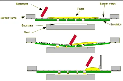
2.1.2 Screen printing ... 34
2.1.3 Infiltration/impregnation ... 36
2.2 Material characterization ... 38
2.2.1 X-Ray Diffraction (XRD) ... 38
2.2.2 Scanning Electron Microscopy (SEM) and Back-Scattered Electron (BSE). ... 40
2.2.3 Energy Dispersive X-ray (EDX) spectroscopy ... 42
2.2.4 Transmission Electron Microscopy (TEM) ... 43
2.2.5 Focused Ion Beam (FIB) ... 44
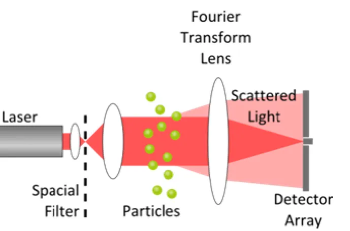
2.2.6 Particle Size Analysis (PSA) ... 47
2.2.7 Brunauer–Emmett–Teller (BET) measurement ... 47
2.2.8 Dilatometry ... 48
2.2.9 Thermal Gravimetric Analysis (TGA) ... 50
2.2.10 Conductivity measurement ... 51
2.3 Electrochemical testing techniques ... 52
2.3.1 Two-electrode, four-probe testing setup ... 52
2.3.2 Current-Voltage (I-V) measurement ... 53
2.3.3 Electrochemical Impedance Spectroscopy (EIS) ... 54
2.3.3.1 AC impedance ... 54
2.3.3.2 Equivalent circuit ... 55
2.3.3.3 Studying the electrical properties of bulk using impedance spectroscopy ... 58
Chapter 3. Characterization of LSCTA- powder and its initial performance for anode-supported SOFCs prepared by aqueous tape casting ... 62
3.1 Characterization of LSCTA- powder ... 62
3.1.1 Analysis of X-ray Diffraction (XRD) ... 62
3.1.2 Particle Size Analysis (PSA) and Specific Surface Area (SSA) .... 65
3.1.3 Scanning Electron Microscopy (SEM) ... 67
3.1.4 Dilatometry ... 68
3.1.5 Thermal Expansion Coefficient (TEC) ... 72
3.1.6 Electrical conductivity ... 76
X
3.2.1 LSCTA- tapes made from the powder calcined at single
temperature…... 79
3.2.2 LSCTA- tapes made from the mixed powder calcined at two temperatures ... 82
3.3 Performance of LSCTA- anode-supported cells ... 87
3.3.1 Microstructure of the cells ... 87
3.3.2 Electrochemical testing ... 89
3.3.3 Microstructure of impregnated anode ... 96
3.4 Conclusion ... 98
Chapter 4. Stability studies of metal-impregnated LSCTA- anode as support for SOFCs ... 99
4.1 Introduction ... 99
4.2 Cell fabrication ... 100
4.3 Results and discussion ... 103
4.3.1 Cell microstructure ... 103
4.3.2 EIS of symmetric LSCF-YSZ cell ... 105
4.3.3 Effects of metallic infiltration on the initial performance ... 106
4.3.4 Stability of bare LSCTA- anode ... 108
4.3.5 Stability of nickel impregnated LSCTA- anode ... 111
4.3.6 Stability of bimetallic Ni0.75Fe0.25 impregnated LSCTA- anode .... 116
4.3.7 The effect of anode porosity on the performance of bimetallic Ni0.75Fe0.25 impregnated LSCTA- anode (see section 4.3.6) ... 123
4.4 Conclusion ... 126
Chapter 5. Performance of LSCTA- anode infiltrated with CeO2 and metal as catalyst ... 128
5.1 Introduction ... 128
5.2 Infiltration ... 130
5.3 Results and discussion ... 131
5.3.1 Initial performance in hydrogen ... 131
5.3.1.1 CeO2 impregnated LSCTA- cell ... 131
5.3.1.2 CeO2+Ni impregnated LSCTA- cell ... 134
5.3.1.3 CeO2+Ni0.75Fe0.25 impregnated LSCTA- cell ... 136
XI
5.3.2.1 CeO2 impregnated LSCTA- cell ... 138
5.3.2.2 CeO2+Ni impregnated LSCTA- cell ... 141
5.3.2.3 CeO2+Ni0.75Fe0.25 impregnated LSCTA- cell ... 145
5.3.3 Stability in hydrogen ... 148
5.3.3.1 CeO2 impregnated LSCTA- cell ... 148
5.3.3.2 CeO2+Ni impregnated LSCTA- cell ... 151
5.3.3.3 CeO2+Ni0.75Fe0.25 impregnated LSCTA- cell ... 161
5.3.4 Redox stability and microstructure of CeO2+Ni impregnated cell……. ... 166
5.4 Conclusion ... 171
Chapter 6. Effects of YSZ/LSCTA- ratio and ball-milling process on sintering processes and electrical properties ... 172
6.1 Introduction ... 172
6.2 Experimental ... 173
6.3 Results and discussion ... 175
6.3.1 Microstructure ... 175
6.3.2 Dilatometry ... 178
6.3.3 Impedance analysis ... 181
6.4 Conclusion ... 187
Chapter 7. Ni-YSZ coating prepared by electroless co-deposition process for an SOFC anode ... 189
7.1 Introduction ... 189
7.2 Experimental ... 191
7.2.1 Preparation of the half cells ... 191
7.2.2 Ni-YSZ co-deposition onto half cells ... 192
7.2.3 Characterization of Ni-YSZ coatings ... 193
7.2.4 Cell performance testing ... 193
7.3 Results and discussion ... 194
7.3.1 XRD pattern ... 194
7.3.2 Ni-YSZ anode without surfactant and pore formers ... 195
7.3.3 Effect of pore formers on the Ni-YSZ anode ... 199
7.3.4 Effect of pore formers and surfactant on the Ni-YSZ anode ... 204
XII
General conclusions ... 208
Suggestions for future work ... 208
1
Chapter 1.
Introduction
1.1 Fuel cell technology
1.1.1 Definition
Fuel cells are energy conversion devices that transfer the chemical energy directly
into electricity through the chemical reaction between a fuel and an oxidant. Across
the different types of fuel cells, a typical fuel cell is composed of three basic elements:
anode (fuel electrode), electrolyte and cathode (air electrode), as shown in Figure 1.1.
The fuel (such as hydrogen or methanol) is fed into the anode and oxidized liberating
electrons to the external circuit; the oxidant (usually air or oxygen) is reduced on the
cathode in combination with electrons from the external circuit. The ions produced
during reduction or oxidation transport from one electrode to the other through
electrolyte that is an ionic conductor but electronic insulator. The electrolyte also
serves as a barrier for gaseous diffusion. The electrons flowing through the external
circuit from the anode side to the cathode side generate the electricity on the load.
Theoretically, a fuel cell system produces electricity continuously as long as the fuel
and oxidant are introduced into the chambers, but the malfunction of each component
can cause the degradation of performance, limiting the practical application.
Figure 1.1 Schematic of a fuel cell: an electrolyte is sandwiched by an anode and a
cathode
Anode
Electrolyte
Cathode
Fuel
Oxidant
External load e
-2
1.1.2 History
The concept of fuel cells has been efficiently demonstrated by Humphry Davy dating
from the early nineteenth century [1]. The first hydrogen fuel cell was successfully
invented by William Grove in 1839 [2], generally referred as the start of fuel cell
history. He discovered a small amount of current flowing between the two platinum
electrodes immersed into the sulphuric acid as a result of the chemical reaction of
hydrogen and oxygen produced from electrolysis reaction of water [3].
Until the early 20th century, much effort had been devoted to the optimization of the
original fuel cells. However, the development of fuel cell technology has been limited
by the electrode materials and manufacturing methods. In 1959, Francis Bacon
successfully prepared a 5KW stationary fuel cell using alkaline solution as electrolyte
and metallic nickel as electrodes, unveiling a prosperous era for development of fuel
cells. Since the early 1960s, significant advances in fuel cell technology have been
achieved: they have been used for space vehicles [4], submarines [5] and power
suppliers for commercial and industrial locations.
Nowadays, with concerns over energy shortage and environmental contamination
caused by combustion of fossil fuel, much work has aimed at the development and
optimization of more efficient and cleaner fuel cell system. In despite of the fact that
fuel cell has been developed for over 170 years, there are still some issues in respect
to process techniques, material selection and stability needed to be addressed to
prompt the practical application.
1.1.3 Classification of fuel cells
According to the different types of electrolytes used in the cells, fuel cells are
classified into 5 major kinds: polymer electrolyte membrane fuel cells (PEMFCs),
alkaline fuel cells (AFCs), phosphoric acid fuel cells (PAFCs), molten carbonate fuel
cells (MCFCs) and solid oxide fuel cells (SOFCs). Generally, the operating
temperature is dependent on the type of electrolyte materials. The first three kinds of
fuel cells are usually operated at the low temperature, while the other two types are
3
fuels, electrolyte materials and conducting mechanism among all kinds of fuel cells
are listed in the Table 1.1 [6].
Table 1.1 Comparison of different types of fuel cells [6]
Type Temperature (Operating o
C) Fuel Electrolyte
Mobile Ion
Polymer electrolyte membrance fuel cell
(PEMFC)
70-110 H2, CH3OH Polymers (H2O)nH +
Alkaline fuel cell
(AFC) 100-250 H2
Aqueous
K(OH) OH
-Phosphoric acid fuel
cell (PAFC) 150-250 H2
H3PO4
(liquid) H
+
Molten carbonate
fuel cell (MCFC) 500-700
Hydrocarbon, H2, CO
(Na, K)2CO3
(liquid) CO3
2-Solid oxide fuel cell
(SOFC) 700-1000
Hydrocarbon, H2, CO
(Zr, Y)O3-δ O
2-Despite of the similar operating principle, significant differences lie in design,
application, efficiency and cost due to varied electrolytes and temperature of
operation. PEMFCs employ solid electrolytes at the low temperature, which reduces
the corrosion and electrolyte management problems; however, they are subjected to
poisoning by the trace contaminants in fuel. Moreover, the need for the high cost
platinum catalyst is another limiting factor for the practical application of PEMFCs.
AFCs as the most mature fuel-cell technologies offer high electrical efficiencies under
non-precious metal catalysts, but suffer from the problem of low resistance to
poisoning by carbon dioxides and liquid electrolyte management. PAFCs are tolerant
to the impurities in hydrogen, such as CO, while the cathodic reaction is slow and
requires the use of the platinum catalyst. In addition, the highly corrosive nature of
phosphoric acid requires the use of expensive materials. Because MCFCs are used at
relatively high temperature, no expensive electro-catalysts are required, and both CO
and certain hydrocarbon can be used as fuels. The challenge for MCFCs stems mainly
4
material problems and causing the performance degradation upon operation. SOFCs
are composed of solid components, which alleviate the corrosion problems in the cell.
The high operating temperature for SOFCs allows using low-cost electro-catalysts and
varied fuels, but it places severe constraints on material selection and manufacturing
processes. And the long-term reliability of the materials under operating conditions is
also of the greatest concern.
The application of solid electrolyte precludes the need for corrosive liquid, prompting
the development of PEMFCs and SOFCs. The SOFC is more demanding than the
PEMFC from the standpoint of materials and has been developed for its potential
application arising from the flexibility of fuel from hydrogen to hydrocarbon then
further to CO, higher energy conversion efficiency operated at high temperature and
less emission of pollutants, compared to the conventional internal combustion engines
and other types of fuel cells.
1.1.4 Advantages
One of the most attractive properties of fuel cells is their extremely high
energy-conversion efficiency which is superior to those conventional internal combustion
engines. Because the fuel cells convert the chemical energy directly into the electrical
energy without thermal energy conversion as intermediate steps, the conversion
efficiency is not confined by the Carnot cycle. Theoretically, the efficiency of fuel
cells is expected to be 40–60% when converting fuel to electricity [7]. If the heat from
the fuel cell system can be captured and utilized, the overall system efficiencies could
be up to 80–85% [7]. For hydrogen fuelled fuel cells, the only product is water. Fuel
cells can eliminate CO emission in exhaust gases by converting into CO2 at high
operating temperature. Besides those advantages, fuel cells offer some additional
5
1.2 Basics of solid oxide fuel cells
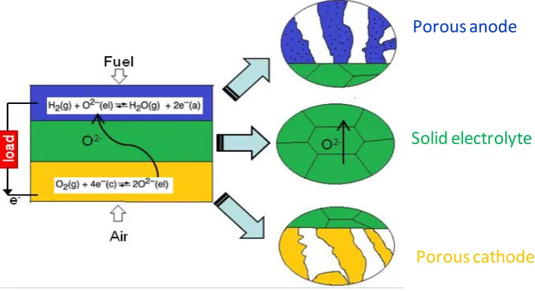
1.2.1 Principles of operation
SOFCs with hydrogen as fuel and oxygen as oxidant have been studied extensively.
The operating principles of a typical SOFC are shown in Figure 1.2 using hydrogen
and oxygen as fuel and oxidant respectively. The anode and cathode must be porous,
to allow fuel and oxidant to access the corresponding triple phase boundaries (TPB)
where gaseous species, ions and electrons meet and the chemical reaction occurs upon
catalyst surfaces [8]. On the cathode side, O2 is absorbed and combines with electrons
to form O2-, which can migrate through the ion conducting electrolyte to the anode
side. On the anode side, supplied H2 reacts with O2- to produce H2O and release
electrons. Consequently, electrical power is generated as the result of the electrons
passing through the external circuit from the anode to cathode.
Figure 1.2 Operating principle of a basic SOFC using H2 as fuel and O2 as oxidant.
The abbreviations g, el, a and c in the reaction equations refer to gas, electrolyte,
anode and cathode, respectively.
Porous anode
Solid electrolyte
[image:20.595.97.484.379.589.2]6
1.2.2 Thermodynamic principles of SOFCs
In a typical SOFC device, oxidant is reduced at the cathode side and fuel is oxidised
at the anode side. If hydrogen and oxygen are used as fuel and oxidant in SOFC, the
overall reaction in the fuel cell is given as
H2 (anode) + 1/2O2 (cathode) = H2O (anode) (Equation 1.1)
where the subscripts anode and cathode refer to the states at the anode and cathode,
respectively.
The reaction of oxygen and hydrogen occurs on the cathode and anode, respectively,
according to Equations (1.2) and (1.3):
O2 (cathode) + 4e- = 2O2- (electrolyte) (Equation 1.2)
H2 (anode) + O2-(electrolyte) = H2O (anode) + 2e- (Equation 1.3)
where the subscript electrolyte represents the oxygen ions transporting through the
electrolyte.
The equilibrium voltage, E, is given by the Nernst equation:
0 2 anode
2 cathode
2 anode
P(H ) ln P(O ) ln
4 2 P(H O )
RT RT
E E
F F
(Equation 1.4)
Where R is the gas constant, F the Faraday’s constant, T the temperature, and
2 cathode
P(O ) , P(H2 anode) and P(H O2 anode) the partial pressure of cathodic oxygen,
anodic hydrogen and water vapour, respectively. 0
E is the equilibrium voltage at the
standard state for oxidation of H2, which can be established by
0 0 0
0
4 4
G H T S
E
F F
(Equation 1.5)
where ∆G0 represents the standard Gibbs energy change of reaction of hydrogen with
oxygen to produce water, ∆H0 is the standard enthalpy change and ∆S0 is the standard
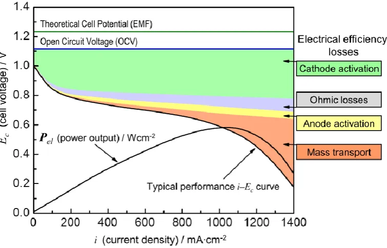
entropy. However, the actual cell voltage Ec under current load is less than the
7
associated with ohmic losses, mass transport and the kinetics of electrode reactions, as
[image:22.595.111.489.136.378.2]depicted in Figure 1.3 [9].
Figure 1.3 Schematic of a current-voltage curve with marked regions of the different
contribution of polarization losses. Image is taken from reference [9].
The maximum thermodynamic efficiency,
, can be obtained only when the Gibbsfree energy of the cell reaction, G, is totally converted into electrical energy,
therein expressed by the following equation:
G H
(Equation 1.6)
where H is the enthalpy changes for the combustion of fuel. In practise, Gis
consumed not only to achieve the cell reaction but also to produce heat and water
vapour above 100oC, resulting in a significant energy losses compared to the
8
1.2.3 Configuration and evolution of SOFCs
Figure 1.4 Planar design of SOFCs. Image is taken from reference [10].
In general, there are two types of SOFC designs: planar and tubular. In a planar cell,
each component is made into flat plates and all components are assembled into a stack
by connecting the interconnect plates of two adjacent cells, shown in Figure 1.4. In
this system, the interconnect plates form gas flow channels for fuel and oxidant and
serve as bipolar gas separators contacting the anode and the cathode of adjoining cells
[image:23.595.93.445.108.342.2][11].
9
Another important type of SOFC configuration is tubular. As illustrated in Figure 1.5,
outside of one electrode is electrolyte and another electrode in order. Generally, one
electrode is fabricated into a long tube by extrusion and sintering, and then the other
components are deposited as a thin layer on the electrode tube. The main advantage of
this type of SOFC configuration is the elimination of gas-tight seal problem and
mechanical strength. However, the cell internal resistance and gas diffusion are the
limiting factors of this design [13].
The development of SOFCs can be divided into three stages according to operating
temperature. The earlier SOFCs were based on electrolyte-supported fuel cells, which
contain a thick yttria-stabilized zirconia (YSZ) layer as electrolyte, operated at high
temperature up to 1000oC [14]. The next generation involves an electrode-supported
fuel cell operating at intermediate temperature (600-800oC), and is the most widely
studied at present. The benefits of lowering the operating temperature can be
summarized in the following ways: 1) increasing the choice of materials, such as
using metallic interconnect; 2) the lower constraints imposed by the cell components
and seals; 3) improved stability and durability [15,16]. Moreover, an anode-supported
fuel cell is preferred due to the higher diffusivity of hydrogen than that of oxygen
through the electrodes with a similar porosity at intermediate temperatures [17,18],
which will decrease the diffusion losses of the whole fuel cell. The third generation
tends to be metal-supported cells, which provide significant advantages over
conventional ceramic cells including low material cost, ruggedness, and tolerance to
rapid thermal cycling and redox cycling [19]. They are believed to achieve a good
performance at lower temperature around 500-600oC as an alternative to the anode-
and electrolyte-supported cells [20~22].
1.3 Electrolyte materials for SOFCs
The electrolyte in SOFCs serves as a separator between the fuel and the oxidant and
an ionic conductor from the cathode to the anode. In terms of its function, the
electrolyte should satisfy several needs, including efficient ionic conductivity,
negligible electronic conductivity and good chemical stability over a broad range of
10
Currently, 8mol.% yttria-stabilized zirconia (YSZ) known as fluorite structure is
widely used as SOFC electrolyte due to excellent ionic conduction at 1000oC and
chemical stability under redox condition. The dopant of the yttria serves two roles
[23]: it stabilizes the high temperature cubic phase in zirconia and also generates
oxygen vacancies through the following defect reaction, as written in Kroger-Vink
notation:
2
ZrO
2 3 Zr O O
Y O 2Y +3O +V' (Equation 1.7)
The high ionic conductivity is attributed to the produced oxygen ion vacancies, which
are created by doping with Y2O3. It has been reported that the highest conductivity
levels can be achieved by doping yttria in ZrO2 at the range of 8-11mol.% [24]. The
further addition could increase the association of the oxygen vacancies into complex
defects of low mobility, and therefore decrease the ionic conductivity. The ohmic
resistance from the thick YSZ electrolyte will cause a significant decrease of power
density at intermediate temperature due to the insufficient ionic conductivity. In
addition, chemical reaction between YSZ electrolytes with the cathode materials to
produce insulating phases is generally of greatest concern [25]; for example, the most
commonly used cathode material, La1-xSrxMnO3 (LSM), in a combination with YSZ
electrolyte, can react with YSZ to produce the electronically insulating phases at high
temperature. In terms of the strontium content in the A-site stoichiometric LSM, the
LSM/YSZ ratio and the temperature, two zirconate phases, i.e., the pyrochlore
La2Zr2O7 and the perovskite SrZrO3, would form at the interface between LSM and
YSZ [26~32].
To decrease the resistance from the YSZ electrolyte, two methods can be employed:
either decreasing the thickness of YSZ electrolyte or using new materials exhibiting a
high ionic conductivity at lower temperature, such as Gd-doped ceria (GDC/CGO)
[ 33 ] and lanthanum strontium gallium magnesium oxide (La1-xSrxGa1-yMgyO3-δ,
referred to as LSGM) [34]. Based on the conductivity data in Figure 1.6, LSGM and
GDC are preferable for being operated at the intermediate temperature. In addition,
GDC has a better chemical stability with high-performance cathode materials, such as
La1-xSrxCoO3 [ 35 ~ 37 ], compared with YSZ. However, GDC electrolyte when
11
and therefore provides a short-circuit pathway [38], which reduces the efficiency of
SOFCs [39]. Furthermore, lattice expansion from the chemical state change between
Ce4+ and Ce3+ in the reducing atmosphere can cause cracks and delamination [40],
resulting in cell degradation.
The conductivity of LSGM is comparable to GDC and much higher than YSZ. LSGM
does not have an easily reducible ion, like Ce4+, and thus is superior to GDC for use in
the reducing conditions [25]. However, it has been found difficult to synthesize a pure
phase electrolyte material of LSGM, and the cathode and anode materials suitable for
LSGM need further development.
[image:26.595.94.376.281.506.2]
Figure 1.6 Comparison of the conductivity data for various ionic conductors: 8-YSZ
(8mol.% Y2O3 doped ZrO2) [41], 10-ScSZ (10mol.% Sc2O3 doped ZrO2)[42], GDC20
(Gd0.2Ce0.8O1.9) [42] and LSGM20 (La0.2Sr0.8Ga0.85Mg0.15O3-δ) [43]
Scandia stabilised zirconia (ScSZ) also gives a high conductivity in intermediate
temperature, as shown in Figure 1.6. This can be attributed to a smaller mismatch in
size between Sc3+ and Zr4+, as compared to that between Y3+ and Zr4+, decreasing
energy for defect association and thus increasing conductivity [44]. However, ScSZ
was not widely used as the SOFC electrolyte material because of its phase transition
and conductivity degradation under operating temperature of SOFCs. Therefore, in
0.6 0.8 1.0 1.2 1.4 1.6 1.8 2.0 2.2
1E-5 1E-4 1E-3 0.01 0.1
C
on
du
ct
ivi
ty
(S
/cm
)
1000/T (1/K)
8-YSZ 10-ScSZ GDC20 LSGM20
1200
1000 800 600 400
Temperature (oC)
12
order to decrease the ohmic loss, a thin film of YSZ electrolyte, typically 40-60m in thickness, was employed in this study.
1.4 Cathode materials for SOFCs
The cathodes for SOFCs as the sites for oxygen reduction need to meet the following
requirements [45]: 1) high electronic conductivity (preferably more than 100S/cm
under oxidizing condition); 2) matched thermal expansion coefficients (TECs) with
electrolyte materials; 3) good chemical compatibility with other cell components; 4)
sufficient porosity for the gaseous species to diffuse to triple phase boundaries (TPBs);
5) good stability in oxidizing condition; 6) high catalytic activity for oxygen reduction.
Strontium-doped lanthanum manganite (LSM) has been known as the most commonly
used cathode material, where substitution of lower valent strontium for lanthanum
enables to increase the content of Mn4+ in oxidizing atmospheres and therefore
enhances the electronic conductivity. However, the Sr dopant does not increase the
oxygen vacancies, which can be explained by the following equation:
3
LaMnO
Mn La Mn O
SrOMn Sr' Mn O (Equation 1.8)
This reaction increases the electron-hole concentration and therefore improves the
electrical conductivity under oxidizing atmosphere; however, this reaction also
suggests that LSM lacks sufficient oxygen ionic conductivity. So the reduction of
oxygen in LSM is restricted to the interface between the electrolyte and the LSM
cathode, where oxygen, electrolyte and cathode are in intimate contact. The limitation
of reaction sites has a great impact on the cell performance when using single phase
LSM as cathode.
The addition of ionic conductor, such as YSZ, to LSM cathodes has been reported to
show a better performance than those composed of single phase LSM, since the TPBs
for reduction of oxygen have been extended into the composite cathode
three-dimensionally [46~49]. In general, the LSM-YSZ composite is prepared by
screen-printing onto the YSZ electrolyte with the inks that contain the LSM, YSZ and pore
13
The calcination temperature should be high enough to yield good LSM particle
percolation but not so high as to cause substantial particle coarsening and
densification [51]. Choi et al. [52] reported that the optimal firing temperature for the
LSM-YSZ composite was 1100oC, when the composite offers the optimum cathodic
performance by compromising the interfacial resistance and the TPB sites. In addition,
infiltration of the nanoparticles of LSM into the porous YSZ backbone has been
demonstrated as an effective method to produce the connected electronic and ionic
transporting networks for SOFC cathodes [50,53~56].
Another way to improve the cathode performance is to replace LSM with mixed ionic
electronic conductors (MIECs), such as strontium-doped LaCoO3 (LSC) [35,57,58],
LaFeO3 (LSF) [59~61] and LaCoyFe1-yO3 (LSCF) [62~64]. They show high electronic
and ionic conductivity at intermediate temperature as well as electrocatalytic activity
for the reduction of oxygen, therefore reducing the polarization losses. LSCF series
show an intermediate performance between LSC and LSF. Their electronic
conductivity, ionic conductivity and also the thermal expansion coefficients (TECs)
are listed in Table 1.2.
Table 1.2 Comparison of the electronic and ionic conductivity (S/cm) at 800oC in air,
and TECs (10-6K-1) of LSC, LSF and LSCF
Typical composition Electronic conductivity
Ionic
conductivity TEC
LSC La0.6Sr0.4CoO3-δ Over 1000 [65] 0.22 [66] 25.0 [67]
LSF La0.6Sr0.4FeO3-δ 128 [67] 5.6×10⁻³ [67] 13.4±0.4 [68]
LSCF La0.6Sr0.4Co0.2Fe0.8O3-δ Around 300 [69] 8×10⁻³ [67] 13.2 [70]
LSC is an attractive cathode material for intermediate temperature SOFCs (below
800oC) because of the higher electronic and oxygen ionic conductivity, and higher
catalytic activity for oxygen incorporation reaction than LSM [71]. However, the
mismatch of thermal expansion coefficients (TECs) between LSC and the typical
14
cracking and delamination of cell components due to the stress developed during
fabrication and operation [72]. Moreover, a highly reactivity between YSZ electrolyte
and LSC cathode forming insulting phases, such as La2Zr2O7 and SrZrO3, is another
drawback hindering its development [61,73] when using YSZ as electrolytes. In order
to minimize the mismatch of TECs between the LSC and electrolyte materials, the
efforts have been made by incorporating LSC into ceria-based cathode backbone to
form a composite cathode [71,74] on ceria-based or LSGM electrolytes.
Despite the lower electronic and ionic conductivity than LSC, LSF exhibits a closely
matched TEC with commonly used electrolyte materials [68], such as YSZ and GDC,
and no detrimental reaction occurs between LSF and YSZ [ 75 ] under sintering
conditions.
In order to achieve a desirable electrochemical performance, along with chemical and
mechanical compatibility with electrolyte materials such as YSZ and GDC, the
combination of LSC and LSF was proposed by incorporating strontium in the A site
and cobalt in the B site on the perovskite LaFeO3, known as La1-xSrxCoyFe1-yO3
(LSCF). Previous research [76~79] has shown that the properties, such as ionic and
electronic conductivity, TEC and reactivity with the YSZ electrolyte are related with
the composition, namely the content of Sr and Co. The electrical and ionic
conductivities increased with increasing Sr and/or Co content, and they show the
highest value for the composition La0.2Sr0.8Co0.8Fe0.2O3. However, the increasing Sr
and Co content causes an increase in thermal expansion >26×10-6K-1, which is not
compatible with the commonly used electrolytes. Therefore the composition with
0.2<x<0.4 and y<0.5 seem to be more attractive as cathode material for SOFCs.
Moreover, in order to prevent the undesired chemical reactions between LSCF
cathode and YSZ electrolyte, two effective methods have been investigated: to
employ GDC as an interlayer [63,64] or prepare the cathode at the low temperature
[80,81]. It has been reported that no impurity phase is observed when LSCF is formed
15
1.5 Anode materials for SOFCs
1.5.1 Requirements for anode
Based on the operation principle and laminated structure, an anode material must
meet some requirements to function efficiently [82]:
1) High electronic conductivity. The electrons produced from oxidation of fuel on the
triple phase boundaries (TPBs) on the anode, where electrons, oxygen ions and fuel
meet together and react, need to be transported to the external circuit. The thicker the
anode layer is, the longer distance electrons travel through the anode to current
collector and therein the higher electronic conductivity the anode requires.
Figure 1.7 Schematic of the sites where the electrochemical reaction occurs for
different types of anode: (a) metal, (b) Ni-YSZ cermet and (c) MIEC. The yellow,
blue and green spheres represent Ni, YSZ and MIEC particles, respectively. The pink
areas indicate TPBs where the oxidation of fuel takes place.
2) High oxygen ionic conductivity. Three types of materials have been employed as
anode for SOFCs: metal (such as Pt and Ni), Ni-YSZ cermet and mixed ionic and
electronic conductor (MIEC, such as Gd-doped ceria). Take metal anode as example,
as shown in Figure 1.7(a), the electrochemical reaction only takes place at the
interface of electrolyte/anode (1-D). For the Ni-YSZ as anode, the TPBs spread out
over the Ni/YSZ particle interface within the bulk anode (in Figure 1.7(b)). When
MIEC being used as anode, the electrochemical reaction is more likely to occur at the
16
clear that the sites where the electrochemical reaction occurs are increased
significantly by applying mixed ionic electronic conductor as anode.
3) High catalytic activity for the oxidation reaction of the fuel. The oxidation of
hydrogen and hydrocarbon on the anode begins with a chemisorption and dissociation,
then followed by a reaction of the products from the dissociation with O2- from the
electrolyte [83]. The catalyst plays an important role in facilitating these reactions to
occur.
4) Chemical stability. The anode is required to be chemically stable not only in the
reducing and oxidizing atmospheres, but also with the electrolyte and current collector
in contact with anode.
5) Thermal compatibility with the contacting components. The thermal expansion of
the anode must match that of the electrolyte and current collector during heating stage
and reduction-oxidation (redox) cycles. Otherwise, the delamination and cracking of
the cell components can be induced by the mismatch, resulting in failure for operation
of the fuel cell.
6) Porosity. Because the gaseous species must transport to the TPBs of the anode and
meet the electron and oxygen ions, the anode need to retain a porous structure during
operation to allow the fuel into and the products out of the anode.
1.5.2 Ni-YSZ cermet anodes
For SOFCs based on YSZ electrolyte, Ni(O)-YSZ cermets are the-state-of-the-art
materials for anode [84,85]. In this composite, YSZ phase acts as a supporting matrix
for metal phase, ensuring a uniform dispersion of nickel particles and inhibiting
coarsening of nickel [86]; the Ni phase provides the electronic conducting pathways
and catalytic activity for hydrogen oxidation.
Because the TECs of Ni metal and NiO are 16.9×10⁻⁶ and 14.2×10⁻⁶/oC [ 87 ],
respectively, much larger than that of YSZ (10.9×10⁻⁶/oC)[88], which has potential to
cause mechanical stresses on the cells, especially upon thermal cycles, lowering Ni
17
compatible with YSZ electrolyte. However, the conductivity would be decreased
with increasing loading of YSZ [ 89 ]. A lot of work has been undertaken for
optimization of the ratio between Ni and YSZ [84,86,90]. Based on the conductivity
and TEC of Ni-YSZ pellets with different content of Ni (vol.%) [86] listed in Table
1.3, nickel-YSZ cermets with 30-50vol.% Ni are more attractive anode materials.
Table 1.3 Electrical conductivity (S/cm) at 900oC and TEC (×10-6K-1) of Ni-YSZ
containing 15-50vol.% Ni [86]
Ni content (vol.%) Conductivity TEC (room temperature-900oC)
15 0.103 10.40
30 40.00 11.64
50 989.00 13.20
Typically, the porosity in the Ni(O)-YSZ anode is achieved by the reduction of NiO
under reducing atmosphere; however, the transition of Ni/NiO upon reduction and
redox cycles tends to cause bulk expansion of the cermet structure [91,92], breaking
the electrolyte and weakening the mechanical strength of the cell [93]. Therefore, it is
necessary to control the Ni/YSZ ratio and distribution in terms of electrochemical and
mechanical properties.
Long-term operation at intermediate (500-800oC) or high temperature (>900oC) is
necessary for SOFC application. The microstructural change is considered as the
dominant factor for the degradation of Ni-YSZ cermet anodes, reflected mainly by the
agglomeration and particle coarsening of the metallic Ni [94]. This could result in the
reduction of triple phase boundary (TPB) and electrical conductivity by loss of nickel
percolation, and subsequently, causing a significant increase in the electrode
polarization resistance for the oxidation reaction of fuels [95]. Simwonis et al. [94]
studied the relationship between the electrical conductivity and nickel particle size of
Ni-YSZ samples in reducing atmosphere. They found an increase of 26% in average
nickel particle size and a decrease up to 33.3% in electrical conductivity for Ni-YSZ
anode after being exposed in 4% H2/3% H2O/Ar at 1000oC for 4000h. Performance
18
air and humidified H2 (3% H2O) as oxidant and fuel, respectively [96]. The results
show that both the cell voltage decay and the Ni growth appear to reach a plateau after
about 800h operation, presenting a strong relationship between degradation and the
coarsening of Ni particles occurring in the anode.
When using hydrocarbon fuels, more disadvantages can be found on Ni-YSZ anodes,
such as low tolerance to sulphur poisoning [97] and carbon deposition [98 ,99 ],
besides the redox instability and nickel coarsening mentioned above. Sulfur is a
common compound in conventional and low-cost hydrocarbon fuels. Upon reforming,
sulfur compounds are converted into hydrogen sulphide (H2S), which inhibits the
rapid catalysis of nickel-YSZ anode, leading to a drastic drop of cell performance and
lifetime [ 100 ]. One hypothesis has been generally acknowledged that the sulfur
poisoning is caused by the strong adsorption of the elemental sulphur on Ni surface,
which blocks the active sites for oxidation of fuel and degrades the cell performance
[90,100~103].
Carbon is another harmful species that can deposit on the metal surface and block the
reaction sites at the triple phase boundary (TPB), increasing the mass transport
resistance and reducing the cell performance [ 104 , 105 ]. Buccheri et al. [ 106 ]
conducted the cell testing in dry methane at 750oC on electrolyte- and
anode-supported Ni-YSZ/YSZ/Pt cells: a remarkable degradation is observed for both cells
possibly due to carbon damaging the anode and blocking pores. The Ni-YSZ
supported cells have shown a rapid degradation from 1.0V to zero in dry methane at
100mA/cm2 within 10h operation due to coking [ 107 ]. However, the carbon
deposition might be oxidized at high current density due to sufficient oxygen supply
from ionic conductor, presented as reversible carbon deposition [99].
1.5.3 Modified Ni-YSZ based anodes
Two approaches have been proposed to solve the problems of Ni-YSZ cermet anode
stated above [108]: one is to replace Ni by other catalytic materials and the other is to
modify the existing structure by alloying Ni with less active elements or decorating Ni
19
Since Cu is known to be a poor catalyst for C-C bond breaking and formation, Cu has
been considered as an alternative to Ni for SOFC anode. Although Cu-YSZ cermets
were found to be stable in hydrocarbon environments, they exhibited low performance
for direct oxidation of hydrocarbon [109,110]. The Cu-YSZ anode performance can
be significantly improved by addition of ceria due to its catalytic property and ionic
conductivity [111]; however, agglomeration and growth of Cu particles is still the
dominant factor for performance degradation in hydrogen [112].
The partial substitution of Ni with other metals is believed to be an alternative to
reduce coarsening of the metallic particles and also achieve good performance.
Ringuedé et al. [ 113 ~ 115 ] have successfully prepared homogeneous mixture of
nanocrystalline powders of (Ni, Co)-YSZ, (Ni, Cu)-YSZ and (Ni, Fe)-YSZ by
combustion synthesis from mixtures of molten nitrates and urea. After reduction at
973K, the Cu-Ni mixtures in the porous YSZ scaffold formed single-phase alloys
[116] and showed an excellent tolerance for carbon formation in dry methane at
1073K [117]. Especially, Cu (80%)–Ni (20%) cermet showed a significant increase in
power density with time during operation in dry methane for 500h due to enhanced
electronic conductivity in the anode [117]. The same behaviour has been observed in
Cu electroplated Ni-YSZ cermet anode: Cu-Ni-YSZ anode supported single cell
shows a slightly lower performance but a more enhanced durability in methane than
those of Ni-YSZ anode supported single cell [ 118 ]. Compared with Ni-SDC
(Ce0.8Sm0.2O1.9) anodes, tri-metal alloys Fe0.25Co0.25Ni0.5-SDC (Ce0.8Sm0.2O1.9) anodes
show a higher power density and a lower polarization resistance [119]. So far, the
improved electrochemical performance has been attributed to the alloy formation and
surface reconstruction effects of the binary/ternary electrocatalysts.
The surface modification on the Ni-YSZ surface with low-energy oxides, such as
Nb2O5 and CeO2, can effectively improve the sulphur tolerance on the anode
[120~122]. A thin layer of the ceria or Nb2O5 nanoparticles on the Ni-YSZ anode
surface can react with H2S as a sulphur sorbent to form oxysulfide, which prohibits
the absorption of sulphur by nickel to form the harmful phase Ni3S2. Compared with
the bare Ni-YSZ anode, the modified Ni-YSZ anode demonstrates a more stable
20
1.5.4 SrTiO3 (STO)-based perovskite anodes
Since the drawbacks of Ni-YSZ cermet anodes restrict the development and
application for SOFCs, some alternative anode materials have been extensively
studied and reported. One of the most promising anode materials is titanate perovskite
with general formula ABO3 because of the multiple oxidation states of titanium
(Ti4+/Ti3+) providing a high electronic conductivity under reducing conditions. Of the
available titanates, strontium titanium oxide, SrTiO3 (STO) has been extensively
reported in the early literatures. As illustrated in Figure 1.8, the Sr atoms occupy the
body centres and TiO6 octahedra take all the corners of every cube, which gives the Sr
atom 12-fold oxygen coordination and the Ti atom 6-fold oxygen coordination. In
1953, the conductivity of strontium titanate was first reported revealing a very strong
dependence of the material’s electrical properties on its state of reduction [124].
However, even in reducing conditions, pure STO shows a very low electronic
[image:35.595.114.378.403.627.2]conductivity, which has prevented its applications as anode material for SOFC.
21
1.5.4.1 A-site doped SrTiO3
Strontium titanate can be converted into a highly semiconducting material by doping
with higher valent cation on the Sr site [125~127]. Promising results have been
achieved with lanthanum strontium titanate (LST). In order to maintain the
electro-neutrality the substitution of Sr2+ with La3+ can be compensated by introducing the
extra oxygen beyond the ABO3 stoichiometry under oxidizing conditions, defined as
‘oxygen excess’ as in the formula LaxSr1-xTiO3+x/2 or creating A-site vacancies, as in
LaxSr1-3x/2TiO3, named ‘A-site deficient’ [128]. The high conductivity in reducing
conditions for A-site deficient sample can be explained by the following equations:
X X
Sr O Sr O
Sr +O V +V +SrO'' (Equation 1.9)
X
O O 2
1 O V +2e + O
2
' (Equation 1.10)
The large value of
V
Sr'' reduces the number of intrinsic Schottky defects pushingEquation (1.9) towards left and hence reducing VO . Equation (1.10) would shift right
to oppose the change, facilitating the removal of lattice oxygen and the associated
generation of free electrons [ 129]. In this case, the substitution of La3+ and the
subsequent increase of A-site deficiency greatly promote the formation of free
electrons. It has been found that A-site deficient strontium titanate have higher
conductivity than the corresponding stoichiometric sample in reducing condition
[130~132]. Reduced composition of A-site deficient La-doped SrTiO3 have shown
conductivities as high as 100S/cm at 800oC in 4% H2/Ar [133]. Moreover, A-site
deficient samples have been found to show a close thermal expansion coefficient with
YSZ electrolyte, high chemical stability under oxidizing and reducing atmosphere,
and low tendency to react with zirconia electrolytes forming SrZrO3 [134,135 ].
Considering these properties, A-site deficient doped strontium titanate reduced at high
temperature is more likely to be considered as a good anode candidate.
It is clear that A-site lanthanum doping significantly improves the electronic
conductivity but is coupled with a low ionic conductivity and a poor catalytic activity
22
illustrated by the poor performance for the cells using LST as anode [136~138]. In
order to achieve a good combination of ionic and electronic conductivity, the cells
with LST and YSZ as anode matrix phase was investigated for the potential use as
anode for SOFCs [139~141].
Moreover, the catalytic activity for hydrogen oxidation can be optimized significantly
by the incorporation of various transition metals, as well as ceria to porous ceramic
anodes. The use of nickel has been found to improve the cell performance
significantly, with an almost five times increase in the maximum powder density
observed in an LST-GDC anode at 800oC in 97% H2+3% H2O[142]. When CeO2 and
Ni were used as impregnates, a remarkable improvement of the anode performance
was observed compared with the anode using pure lanthanum strontium calcium
titanate (LSCTA-) or impregnated with ceria only at 900oC in pure hydrogen with 1%
H2O [143,144]. The amount of catalyst incorporation into a porous anode can also
have an important effect on the fuel cell performance. The cermet of 10wt.%
Ni/YST-YSZ showed the minimal polarization resistance among nickel concentrations ranging
from 5 to 50wt.% and stable cell performance even after five consecutive redox cycles
operated at 1000oC in humidified hydrogen (0.6% H2O) [145]. Sun and Fan et al.
[136,146] have also found that the addition of ceria/GDC can significantly improve
the anode structure, and thus fuel cell performance. A-site deficient Y0.07Sr0.895TiO3-δ
(YST) with infiltration of 3wt.% NiO exhibited a cell performance of over 1.0Acm-2
at 0.7V and 800oC in dry hydrogen, which already reached the practical application
level [147]. Recently, the nano-scale electrocatalytic active particles exsoluted from
the doped LST matrix is regarded to be an effective way to promote the anode
performance dramatically and prevent the sintering and agglomeration of
nanoparticles under redox cycles and operation at high temperature [148~153].
While nickel is found to show the highest catalytic activity for oxidation of hydrogen,
other metals are also found to present sufficient catalytic activity and good resistance
against sulphur poisoning especially combined with ceria or gadolinia-doped ceria
(GDC). Savaniu et al. [154~157] have studied La0.2Sr0.7TiO3 anode impregnated with
20mol.% GDC and copper, demonstrating that power densities in excess of 0.5Wcm-2
23
al. [158] have reported that the ceria- and Ru-infiltrated YST-YSZ anode showed a
high sulphur tolerance in 10-40ppm H2S and drastically decreased the polarization
resistance from 2.9Ωcm-2 for the non-infiltrated cell to 0.5Ωcm-2 at 800oC in 3%
humidified hydrogen. The combination of ceria and Pd has been demonstrated as an
effective catalyst to improve the cell performance on LSTM (La0.4Sr0.6Ti0.8Mn0.2O3)
[159,160] and LST-YSZ [161] anode. Samaria-doped ceria (SDC) is also discovered
to be more effective in both electrical conductivity and electrocatalytic activity
towards the oxidation of fuels than YSZ, resulting in a relatively higher performance
of 140mWcm-2 for Ni/YST-SDC compared with that of Ni/YST-YSZ (115mWcm-2)
in 1000oC using humidified H2 (3% H2O) as fuel [162].
1.5.4.2 B-site doped SrTiO3
Many efforts have also been devoted to enhancing the electronic conductivities of
SrTiO3 materials by the replacement of Nb in B site. The substitution of pentavalent
Nb5+ for the host cation Ti4+ has been reported to drastically enhance the electronic
conductivity by an increased electronic compensation due to the formation of Ti3+ and
Nb4+ [ 163 , 164 ]. Blennow et al. [ 165 ] studied Nb-doped SrTiO3, (STN,
Sr0.94Ti0.9Nb0.1O3-δ) as a SOFC anode material in terms of electrochemical properties
and redox stability, showing a promising redox stability feature. However, the ionic
conductivity of STN pre-reduced at 980oC was insufficient as an anode when
compared with the composite electrode of YSZ and STN. As expected, the
electrochemical performance of the anode was greatly improved with increasing
Ni-CGO loadings, and showed a strong dependence on the structural parameters of the
electrode (porosity, pore size etc.) [166]. Similarly, Ni-CGO infiltrated STN:FeCr
composite anode showed a comparable performance and promising durability
properties; 0.7A/cm2 was recorded under 0.6V at 650oC in 4% humidified hydrogen
for the button cell with active surface area of 0.5cm2 [167]. Ramos et al. [168]
reported a preliminary comparison of the impact of catalyst M: Ni, Pd, Ru on the
impedance and stability of M/GDC co-infiltrated STN/YSZ SOFC anodes. They
found that the total polarization resistance (Rp) decreased in the order Ni/GDC >>
Pd/CGO > Ru/CGO and Ru/CGO stayed reproducibly around 20mΩcm2 over 200h at
24
An alternative approach has been proposed by partially substituting the reducible
lower-valence transition metal cations for the Ti4+ cations, which may not only
improve the electronic conductivity, but also introduce oxygen vacancies that lead to
significant ionic conductivity [169]. Rothschild et al. [170] studied the electronic
structure, defect chemistry, and transport properties of mixed ionic electronic
conducting SrTi1-xFexO3-y (STF): STF exhibited mixed ionic and electronic
conductivity at elevated temperatures, with a predominant transformation from p-type
conductor at high oxygen partial pressure (cathode condition) to n-type conductor at
low oxygen partial pressure (anode condition). The test of an LSGM
electrolyte-supported cell with SrTi1-xFexO3-y (x=0, 0.4 and 0.7) mixed with GDC as anode,
La0.4Ce0.6O2 as barrier layer and LSCF as cathode indicates that the Fe-containing
anodes yielded much lower total cell resistance and higher performance than SrTiO3
[169]. A maximum power density of 337mW/cm2 can be achieved for the
SrTi0.3Fe0.7O3-δ-GDC anode cell with thick LSGM electrolyte (0.6mm) at 800oC in ~3%
H2O/97% H2.
1.5.4.3 A- and B-site co-doped SrTiO3
In recent years, (La)SrTiO3-based oxides doped with various transition metal
elements (Cr, Co, Mn, Ni, Mg etc.) on the B site have also been developed in order to
optimize the electronic and/or ionic conductivity. It is generally acknowledged that
donor doping in the Sr site tends to increase the electrical conductivity, while acceptor
doping in the Ti site has the possibility to improve the ionic conductivity [127,130]. In
addition, B-site transition metal may provide the catalytic activity to promote the
fuel-oxidation processes.
Danilovic et al. [ 171 ] have investigated a series of perovskite oxides
La0.75Sr0.25Cr0.5X0.5O3-δ (LSCX, X=Co, Fe, Ti, Mn) as solid oxide fuel cell
electrocatalysts. The Ti-containing composition showed the minimum fuel cell
performance in methane and hydrogen due to the lowest catalytic conversion for fuels
from Ti among all the doped transition metals, while all the compositions provided
the sufficient electronic conductivity in reducing atmosphere. In addition, it was
![Figure 1.5 Tubular design of SOFCs. Image is taken from reference [12].](https://thumb-us.123doks.com/thumbv2/123dok_us/8927436.391586/23.595.93.445.108.342/figure-tubular-design-sofcs-image-taken-reference.webp)
![Figure 1.6 Comparison of the conductivity data for various ionic conductors: 8-YSZ (8mol.% Y2O3 doped ZrO2) [41], 10-ScSZ (10mol.% Sc2O3 doped ZrO2)[42], GDC20 (Gd0.2Ce0.8O1.9) [42] and LSGM20 (La0.2Sr0.8Ga0.85Mg0.15O3-δ) [43]](https://thumb-us.123doks.com/thumbv2/123dok_us/8927436.391586/26.595.94.376.281.506/figure-comparison-conductivity-various-ionic-conductors-doped-doped.webp)


![Figure 2.13 Principle of the dilatometer. Image is taken from reference [221].](https://thumb-us.123doks.com/thumbv2/123dok_us/8927436.391586/63.595.91.487.202.480/figure-principle-dilatometer-image-taken-reference.webp)
