Efficient 5G Communication System using Random
Access Block Interleaving with ETU Channel
Fakeha Khan
M. Tech ScholarDepartment of Computer Science & Engg. Truba College of Science & Technology, Bhopal
ABSTRACT
This work investigates an uplink multiple access technique with Interleave Division Multiple Access using Random Interleaving and Extended Typical Urban (ETU) channel model. The crucial requirement is a better Bit
performance of the proposed system. The article analyzes and compares the performance of proposed system, taking different block lengths and a different number of subscribers, against that SUI. The simulation results show that w increase in block length, the performance of random access block interleaving with the SUI channel we see that SUI performs better then AWGN channel.
Keywords
Random access block interleaving, ETU, Block length, BER
1.
INTRODUCTION
The fast growth of mobile Internet together with the rapid expansion of the IoT will require huge improvements such as high spectral efficiency and massive connectivity for 5G systems. To address these requirements, several novel technologies have been analysed, such as massi
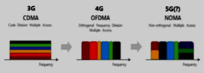
(Multiple-Input Multiple-Output), millimetre communication and non-orthogonal multiple access (NOMA). NOMA’s principle of operation is based on accommodating a large number of subscribers via non-orthogonal resource allocation. Traditionally, in wireless communications only orthogonal multiple access (OMA) techniques were used: frequency-division multiple access (FDMA) for 1G, time division multiple access (TDMA) for 2G, code multiple access (CDMA) for 3G and orthogonal frequency division multiple access (OFDMA) for 4G.
Figure 1Evolution of mobile communications multiple access technologies
NOMA is able to accommodate multiple subscribers that share time and frequency in the same layer by means of power domain and code domain multiplexing schemes. Let us briefly review some of these schemes in order to gain general insights of the global NOMA landscape.
This NOMA scheme, which can be also applied in the uplink, consists on linearly adding up the signals for different subscribers at the base station (or eNodeB in the LTE context). This addition is performed taking into account the restrictions in the transmitted power, by weighting each signal
Efficient 5G Communication System using Random
Access Block Interleaving with ETU Channel
Department of Computer Science & Engg. Truba College of Science & Technology, Bhopal
Amit Saxena
Professor,Department of Computer Science & Engg. Truba College of Science & Technology, Bhopal
This work investigates an uplink multiple access technique with Interleave Division Multiple Access using Random Interleaving and Extended Typical Urban (ETU) channel is a better Bit-Error Rate performance of the proposed system. The article analyzes and compares the performance of proposed system, taking different block lengths and a different number of subscribers, against that SUI. The simulation results show that with an increase in block length, the performance of random access block interleaving with the SUI channel we see that SUI
Random access block interleaving, ETU, Block length, BER
obile Internet together with the rapid expansion of the IoT will require huge improvements such as high spectral efficiency and massive connectivity for 5G systems. To address these requirements, several novel technologies have been analysed, such as massive MIMO Output), millimetre-wave orthogonal multiple access (NOMA). NOMA’s principle of operation is based on accommodating a orthogonal resource in wireless communications only orthogonal multiple access (OMA) techniques were used: division multiple access (FDMA) for 1G, time-division multiple access (TDMA) for 2G, code-time-division multiple access (CDMA) for 3G and orthogonal
frequency-Figure 1Evolution of mobile communications multiple
NOMA is able to accommodate multiple subscribers that share time and frequency in the same layer by means of power multiplexing schemes. Let us briefly review some of these schemes in order to gain general insights
This NOMA scheme, which can be also applied in the uplink, consists on linearly adding up the signals for different s at the base station (or eNodeB in the LTE context). This addition is performed taking into account the restrictions in the transmitted power, by weighting each signal
by a specific coefficient. Then, Successive Interference Cancellation (SIC) is employed
in the LTE context). For simplicity’s sake, let us consider only 2 devices in this example. Since the channel conditions may be very different among subscribers, SIC is performed at subscribers with high
signal-(SINR) following a descending SINR order, as pictured in Figure 1.1. By exploiting the SINR difference among subscribers (caused by the near
power allocation at the base station), multi (MUD) can be successfully achieved.
A conventional DS/CDMA system treats other subscribers as noise, but multi-subscriber receivers attempt to mitigate the interference from other subscribers for their mutual benefit. Linear and non-linear techniques are used for mul
reception: these will be discussed in more detail below. Until recently most multi-subscriber receiver designs have only considered channel coding as a additional gain and not part of the multi-subscriber receiver; this is what we will call a subscriber receiver without coding. New multi
receiver designs consider the coding by generating suitable input metrics for the decoding function; we call this multi subscriber receivers with coding.
In a cellular system a number of mobil
communicate with one base station. Each mobile is only concerned with its own signal while the base station must detect all the signals simultaneously. Multi
reception in this work is therefore aimed primarily at the base station receiver design for subscribers within the cell of interest.
2.
SYSTEM MODEL
2.1 Random Access Block Interleaving
Firstly, the uncoded input subscriber data is spread by spreading sequence. This data after being spread is denoted by di,m (where i denotes the ith subscriber and m gives the mth chip in spread data). This diis then randomly permuted by a random interleaverπ_iproducing xi. In MATLAB, the random interleaver module randomly chooses a permutation table using the ’Initial Seed’ parameter. This same ‘In
used in a corresponding Random Deinterleaver module to restore the original ordering.
At receiver (Fig 13), the signal being received is the combination of all subscribers’ transmitted signal and channel noise. This is expressed as [1]
rm h x
Where, n(m) is the channel noise with variance σ_n^2. For the kth subscriber, the interference from other subscribers can be seen as a part of noise. Therefore, the above equation can be written as[1]:
Efficient 5G Communication System using Random
Access Block Interleaving with ETU Channel
Amit Saxena
Professor, GuideDepartment of Computer Science & Engg. Science & Technology, Bhopal
by a specific coefficient. Then, Successive Interference Cancellation (SIC) is employed at the receiver device (or UE in the LTE context). For simplicity’s sake, let us consider only 2 devices in this example. Since the channel conditions may be very different among subscribers, SIC is performed at - to-interference power ratio (SINR) following a descending SINR order, as pictured in Figure 1.1. By exploiting the SINR difference among subscribers (caused by the near-far effect or by non-uniform power allocation at the base station), multi-user detection
e successfully achieved.
A conventional DS/CDMA system treats other subscribers as subscriber receivers attempt to mitigate the interference from other subscribers for their mutual benefit. linear techniques are used for multi-subscriber reception: these will be discussed in more detail below. Until subscriber receiver designs have only considered channel coding as a additional gain and not part of subscriber receiver; this is what we will call a multi-subscriber receiver without coding. New multi-multi-subscriber receiver designs consider the coding by generating suitable input metrics for the decoding function; we call this multi-subscriber receivers with coding.
In a cellular system a number of mobile subscribers communicate with one base station. Each mobile is only concerned with its own signal while the base station must detect all the signals simultaneously. Multi-subscriber reception in this work is therefore aimed primarily at the base eceiver design for subscribers within the cell of
Random Access Block Interleaving
Firstly, the uncoded input subscriber data is spread by spreading sequence. This data after being spread is denoted by th subscriber and m gives the mth chip in spread data). This diis then randomly permuted by a random interleaverπ_iproducing xi. In MATLAB, the random interleaver module randomly chooses a permutation table using the ’Initial Seed’ parameter. This same ‘Initial Seed’ is used in a corresponding Random Deinterleaver module to
At receiver (Fig 13), the signal being received is the combination of all subscribers’ transmitted signal and channel
x m nm
13
rm h x m ζm
Where,
ζm h′x ′m nm
′
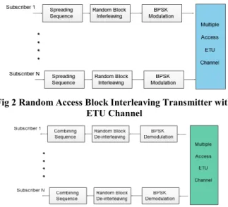
Therefore, ζ_i (m) includes Multiple Access Interference (MAI) from different subscribers and also channel noise. 1) Transmitter and Receiver Structure of Random Access Block Interleaving with SUI channel
Fig 2 and Fig 3 show the transmitter and receiver structure of Random Access Block Interleaving scheme where K subscribers simultaneously access the channel. It has to be noted that we have used uncoded Random Access Block Interleaving system i.e. no Forward-Error-correction (FEC) is applied to input data.
2) Random Access Block Interleaving- Deinter leaving and Multi-User Detection
Multi-User Detection is a technique employed at the receiver of any communication system which enhances performance by processing the signals altogether from different subscribers accessing the multiple access channel[9]. Random Access Block Interleaving performs better because it employs a low complexity chip-by-chip iterative MUD technique on systems with quite a large number of subscribers. Here, the normalized MUD cost per subscriber doesn’t depend on the number of subscribers in the system[1].
Fig 2 Random Access Block Interleaving Transmitter with ETU Channel
Fig 1 Random Access Block De-Interleaving Receiver with ETU Channel
Random Access Block Interleaving uses an Elementary Signal Estimator (ESE) and single subscriber a-posteriori probability (APP) decoders (DEC)[1]. The work of ESE is to find a joint solution considering all subscribers and hence the complexity per subscriber depends on the number of subscribers. DEC, on the other hand, handles data only for one subscriber, so its complexity per subscriber is not dependent on subscriber count[1].The ESE as well as DEC blocks estimate about x_i (m) and their outputs are extrinsic log-likelihood ratios (LLR) given as[1], [10]
ex m logpy|x m 1py|x m −1 ∀ i, m
e x m is the LLR output from ESE block and
e!"x m is the LLR output from DEC block.
2.2
ETU Channel Model
Each ETU channel model outlines specific parameters to represent microscopic effects in a wireless channel such as fading, tapped delay line, antenna directivity along with macroscopic channel effects like path loss and shadowing[8]. In this work, we have used ETU model. There are three taps in each ETU channel model. Parameters relative delay, relative power, K-Factor and maximum Doppler Shift characterize each tap. The multipath fading is modeled as a tapped delay line with three taps with non-uniform delays. The gain associated with each tap is marked by a distribution (Rician with a K-factor > 0, or Rayleigh with K-factor = 0) and the maximum Doppler frequency[7].The objective of the simulation of SUI channel model is to generate channel coefficients at arbitrary sampling rate [8]. Below is the specification of ETU channel as provided in[7]
3.
PROPOSED METHODOLOGY
The proposed approach uses RABI with random block interleaving to enhance BER performance. In this proposed methodology, we’re using random interleavers. Here, we have evaluated BER performance by taking four different block sizes- 50,100,150,200. Also, BER performance is calculated for three cases taking four subscribers, six subscribers, and eight subscribers separately. Data length taken is 128 bits and the spreading sequence length is 6. Number of iterations performed in this simulation are five. The modulation technique used in the proposed methodology is Binary Phase Shift Keying (BPSK) and the simulation of the proposed system is performed in MATLAB. We simulate RABI system along with ETU channel using MATLAB.
3.1
Algorithm for simulation of RABI
system in ETU Channel
Step 1: Select the number of subscribers and block length and initialize simulation model.
Step 2: Generate data for transmission as well as spreading sequence to spread the data.
Step 3: Perform Random Interleaving on chips.
Step 4: Modulate the data using BPSK modulation technique. Step 5: Generate noise to be added to thesignal.
Step 6: Combine signal at receiver with noise and receive signal serially.
Step 7: Estimation of the received signal by performing a specific number of iterations. The algorithm of multi-user chip-by-chip detection is as follows[1]:
Step 8: Perform BPSK Demodulation. Step 9: Calculate Bit-Error Ratio
Step 10: Repeat steps 1-9 for other set of subscribers. Step 11: Display Results
1. If prior information is not available, the means and variances of all transmitted chips are set to zero and one respectively. So we initialize the LLR output of DEC as zero i.e. e!"x m 0.
2. Calculate the value Ex m and Varx m
Varx m 1 − *Exm+,
These values of Ex m and Varx m are used by ESE to update interference mean and variance.
3. Estimate the mean and variance of r(m)
Erm h Ex m
Varrm |h |, Varx m σ
-,
4. Estimate the mean and variance of ζm
E *ζm+ E *rm − h Ex m+
Var *ζm+ Varrm − |h |,Varx m
5. LLR output of ESE
e x m 2h .rm − E *ζm+
Var *ζm+ /
6. This e x m is used as an input to the DEC block. The DEC block applies APP decoding for x m and updates the mean and variance for the next iteration. In the last iteration, DEC gives ‘hard’ decisions.
3.2
Flowchart
The flow chart (Fig 4) depicts step-by-step procedure of this simulation.
4.
SIMULATION RESULT AND
COMPARISON
15
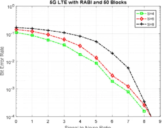
Fig 2 BER-SNR Performance over ETU channel with 50 block size.
The simulation results show that with an increase in block length, the performance of RABI with ETU performs even better sometimes. The optimum performance of the proposed system is obtained at 50 block length with 8 subscribers.
Fig 6 BER-SNR Performance over ETU channel with 100 block size.
Fig 7 BER-SNR Performance over ETU channel with 150 block size.
This superior performance of ETU channel is obtained when the length of interleaver is large. For large block size interleavers, most random interleavers perform well because of low correlation between information input data and soft output of decoder [11].
Fig 8 BER-SNR Performance over ETU channel with 200 block size.
The variables that can be controlled, it is possible to devise a system which could provide optimum and desired levels of performance. Here, the variables are block length and number of subscribers. This article shows the better performance of RABI system using ETU channel.
5.
CONCLUSIONS
In this study, the performance of RABI system in transmission over the ETU channel catches up with the same with AWGN channel and we see that ETU performs similarly to AWGN channel even better sometimes. Hence, with ETU channel modeling, it is possible to get better performance compared to AWGN channel. AWGN is not a suitable model for many terrestrial links due to interference and multipath terrain blocking but ETU model considers these effects. Hence, ETU channel model is a more practical model as compared to the ideal AWGN model and the proposed system shows that its performance in the practical scenario is similar to the ideal case.
6.
REFERENCES
[1] B. Wang, K. Wang, Z. Lu, T. Xie and J. Quan, "Comparison study of non-orthogonal multiple access schemes for 5G," 2015 IEEE International Symposium on Broadband Multimedia Systems and Broadcasting, Ghent, 2015, pp. 1-5.
[2] T. Y. Tseng, C. P. Lee, S. C. Lin and H. J. Su, "Non-orthogonal compute-and-forward with joint lattice decoding for the multiple-access relay channel," 2014 IEEE Globecom Workshops (GC Wkshps), Austin, TX, 2014, pp. 924-929.
[3] A. Benjebbour, A. Li, Y. Kishiyama, H. Jiang and T. Nakamura, "System-level performance of downlink NOMA combined with SU-MIMO for future LTE enhancements," 2014 IEEE Globecom Workshops (GC Wkshps), Austin, TX, 2014, pp. 706-710.
[4] S. Zhang, X. Xu, L. Lu, Y. Wu, G. He and Y. Chen, "Sparse code multiple access: An energy efficient uplink approach for 5G wireless systems," 2014 IEEE Global Communications Conference, Austin, TX, 2014, pp. 4782-4787.
[5] X. Chen, A. Benjebbour, A. Li and A. Harada, "Multi-User Proportional Fair Scheduling for Uplink Non-Orthogonal Multiple Access (NOMA)," 2014 IEEE 79th Vehicular Technology Conference (VTC Spring), Seoul, 2014, pp. 1-5.
[6] H. Osada, M. Inamori and Y. Sanada, "Non-Orthogonal Access Scheme over Multiple Channels with Iterative
0 1 2 3 4 5 6 7 8 9
Signal to Noise Ratio
10-4 10-3 10-2 10-1
100
5G LTE with RABI and 100 Blocks
S=4 S=6 S=8
0 1 2 3 4 5 6 7 8 9
Signal to Noise Ratio
10-4 10-3
10-2 10-1
100 5G LTE with RABI and 200 Blocks
Interference Cancellation and Fractional Sampling in MIMO-OFDM Receiver," 2013 IEEE 78th Vehicular Technology Conference (VTC Fall), Las Vegas, NV, 2013, pp. 1-5.
[7] Ding, Z., Adachi, F., & Poor, H. (2016). The Application of MIMO to Non-Orthogonal Multiple Access. IEEE Transactions On Wireless Communications, 75(1), 537-552.
[8] L. Ping, L. Liu, K. Wu, and W. K. Leung, “Interleave-Division Multiple-Access,” IEEE Trans. Wirel. Commun., vol. 5, no. 4, pp. 938–947, 2006.
[9] L. Ping, “Interleave-Division Multiple Access and Chip-by-Chip Iterative Multi-User Detection,” IEEE Commun. Mag., vol. 43, no. 6, pp. S19–S23, 2005.
[10] M. Moher and P. Guinand, “An iterative algorithm for asynchronous coded multiuser detection,” IEEE Commun. Lett., vol. 2, no. 8, pp. 229–231, 1998. [11] A. Tarable, G. Montorsi, and S. Benedetto, “Analysis
and design of interleavers for CDMA systems,” IEEE Commun. Lett., vol. 5, no. 10, pp. 420–422, 2001. [12] S. Bruck, U. Sorger, S. Gligorevic, and N. Stolte,
“Interleaving for outer convolutional codes in DS-CDMA systems,” IEEE Trans. Commun., vol. 48, no. 7, pp. 1100–1107, 2000.
[13] R. Jain, “Channel Models - A Tutorial,” 2007. [Online]. Available:
http://www.cse.wustl.edu/~jain/wimax/ftp/channel_mode l_tutorial.pdf. [Accessed: 16-Jun-2016].
[14] V. Erceg and E. Al., “Channel Models for Fixed Wireless Applications Background,” IEEE 802.16 Broadband Wireless Access Working Group <http://ieee802.org/16>, 2001. .
[15] D. Baum, “Simulating the SUI channel models,” IEEE 802.16 Broadband Wireless Access Working Group <http://ieee802.org/16>. 2001.
[16] S. Moshavi, “Multi-user detection for DS-CDMA communications,” IEEE Commun. Mag., vol. 34, no. 10, pp. 124–135, 1996.
[17] L. L. L. Liu, W. K. Leung, and L. P. L. Ping, “Simple iterative chip-by-chip multiuser detection for CDMA systems,” 57th IEEE Semiannu. Veh. Technol. Conf. 2003. VTC 2003-Spring., vol. 3, no. 4, pp. 2157–2161, 2003.