Rendering an In-browser, 360-Degree
Environment from Disjoint Live Camera
Feeds
Luke John Fernandez
An Honors Thesis
Presented to the Faculty of
The University of North Carolina at Chapel Hill For completion of the B.S. in Computer Science
Department of Computer Science April 2017
Diane Pozefsky, Thesis Adviser Date
c
Rendering an In-browser, 360-Degree
Environment from Disjoint Live Camera Feeds
by
Luke John Fernandez
Submitted to the Department of Computer Science in April 2017, in partial
fulfillment of the Bachelor’s of Science Degree in Computer Science
Abstract
This thesis details a novel approach to the rendering of a real-time 360-degree
in-browser environment from a set of disjoint live camera feed. Developed to give police
officers better visibility and reporting in the field, this study and the lessons learned
during implementation demonstrate progress toward solving a high-stakes limited
resolution and affordability problem that occurs when rendering panoramas from
Acknowledgements
Without the support of my family and dearest friends, this journey would not have
been a possibility. Each of you deserves all of the credit and more.
I would also like to sincerely thank Professor Diane Pozefsky for sticking with me
throughout completion of this project and for giving me the constructive criticism I
needed to stay on track.
Lastly, I am indebted to Professor Jan-Michael Frahm for helping me comprehend
the Computer Vision principles necessary to produce this final result, filling in my
To those who have stood by me through the years.
Contents
Abstract . . . iii
Acknowledgements . . . iv
List of Figures . . . viii
1 Introduction 1 1.1 Motivation . . . 1
1.2 Related Work . . . 2
1.3 Contribution . . . 3
2 Strategy and Approach 4 2.1 Problem Breakdown . . . 4
2.2 Requirements and Considerations . . . 5
2.3 Proposed Solution Architecture . . . 6
2.4 Targeted Proof-of-concept Architecture . . . 7
3 Technology Selection 11 4 Implementation and Analysis 16 4.1 The Components and Their Action Segments . . . 16
4.2 How the Action Segments Come Together . . . 17
4.3 Action Segment Breakdown and Analysis . . . 18
4.3.2 Grab Frames from Cameras . . . 20
4.3.3 Process Frames to be Square and Power-of-two . . . 21
4.3.4 Compose Frames into Atlas . . . 21
4.3.5 Stream Atlas Data Across Network Protocol . . . 22
4.3.6 Relay Atlas Data to Receiver as Buffer . . . 24
4.3.7 Decode Buffer from Network Protocol Back Into Atlas . . . . 24
4.3.8 Decompose Atlas into Six Individual Frames Via UV Mapping 25 4.3.9 Render Frames to Skybox . . . 25
4.3.10 Update Skybox When New Frames Are Available . . . 26
5 Discussion and Conclusion 28 5.1 Summary of Results . . . 28
5.2 Implications of Research . . . 28
5.3 Lessons Learned . . . 29
A Codebase and Documentation 31
List of Figures
2.1 Architecture Proposed for Solving the Underlying Police Problem . . 6
2.2 Architecture Targeted for Proof-of-concept . . . 8
2.3 Camera Configuration . . . 10
3.1 Mapping Architecture Hardware to Components and Technologies . . 11
3.2 Relationship Between Cube Maps and Skyboxes . . . 13
4.1 Components and Their Corresponding Action Segments . . . 17
Chapter 1
Introduction
1.1
Motivation
This thesis investigates a problem brought about by attempts to increase transparency
in a world of media heavily focused on police and civilian engagements, the topic of
police brutality, and the negative direction in which police and civilian relations have
been going in recent times. Out of this overarching problem comes an interesting
technology problem that, if solved, could change the way that police and those they
serve coexist. The project goal was to build out a camera configuration and
soft-ware package pairing capable of recording and streaming a live 360-degree in-browser
rendered scene constructed from cameras atop a police car in the field.
Solving this problem has a number of core parts that, if focused upon and shown
together in a proof of concept, demonstrate a high probability of success for
com-pletion of a full solution. After presenting an overall proposed solution, we focus on
those parts to demonstrate viability and create a foundation for future design and
development.
In this thesis, we aim to share a novel approach to the rendering of a real-time,
the reader through an attempted proof-of-concept implementation of that approach
and illustrate the good and the bad decisions made during said implementation. We
hope to set up future developers to leverage the technologies investigated and lessons
learned herein to build out full solutions to the police and other related problems.
There are many examples out there showing the ability to stream video from an
off-the-shelf, relatively inexpensive camera. There are also some examples that exist
of streaming 360-degree video from one or two off-the-shelf 360-degree cameras. But
there are two specific issues with using this particular technology in our solution:
resolution of the resultant 360-degree rendering and the general cost of the overall
setup.
1.2
Related Work
Let’s explore some of the related work that we referenced during our project design.
The Department of Electrical Engineering at the Linkpings Universitet in Sweden
[12] developed a camera system for increasing safety and maneuverability of heavy
vehicles with blindspots that impede the driver’s view. To remove those blindspots,
researchers built a prototype of a camera system using two fisheye cameras with a
wide field of view. The problem with this setup is that two fisheye cameras do not
give us the resolution we need for our solution.
Google has also done work in this space, filing a patent back in 2006 for a
360-degree surveillance system capable of storing live or recorded video to a portable
digital storage medium and sending it across a wireless communications system for
viewing on the other end [6]. The patent focuses on a fixed lens unit with a single
360-degree panoramic view, which is not feasible for our project because of its high
Researchers at USC also walked through the process of capturing individual video
feeds from a five-camera configuration that they then combined for live and later
viewing on a head-mounted display [10]. In their implementation, they sought to
craft a solution for acquiring high-resolution panoramic images. They were able to
take in live and recorded video feeds, correct the distortion on those feeds, and create
a panoramic image in memory with the frames for those feeds. They then displayed
an image from that panorama on-screen for a user to explore in a head-mounted
display. This is different from our proposed solution because it required specialized
hardware and proprietary software, and we wanted to build a result from off-the-shelf
hardware and open-source software technologies.
One last related work worth mentioning is one completed by a team at Texas
A&M University [8]. Their intent was to develop a video system that could replace
the windows of NASA spacecraft in flight. The main idea of their effort was to
collect a number of high-definition camera feeds and stitch them together in
real-time to generate a panoramic video stream. But they did not focus on rendering a
360-degree panorama, which is what we aimed to do.
1.3
Contribution
This thesis contributes to the computer science body of knowledge by focusing on the
high resolution and affordability of the solution. Our final implementation was not
Chapter 2
Strategy and Approach
As mentioned in Chapter 1, the driving problem for this thesis came out of an attempt
to increase transparency during interactions between police and the civilians they
serve. That problem is better defined in this chapter and can be broken into three
fundamental oversights in the way that law enforcement currently operates. Knowing
this breakdown is what enabled us to design and propose a solution.
2.1
Problem Breakdown
First, police officers in the field have limited visibility into their engagements at the
time of engagement and after completion of the engagement. Today’s dashboard and
body cameras only record events from one point of view. This is cause for concern for
a number of reasons, but it is most easily exhibited by an incident of claimed police
brutality. In a case where a civilian claims to be a victim of police brutality, there
can be two ways that the situation could have played out in reality: either the police
officer was responsible for the act in question or the claim made was a false claim and
the officer is innocent. But, with the current setup, if either party is out of view of
Second, police chiefs and police station operators currently have limited access to
live events. Though dash cams and body cams exist, that footage is not accessible
by the police chiefs back at the station until long after the event is over. So, they
cannot respond to events in real-time unless they are called upon by a police officer
in the field. This inherently endangers police officers when they are on the job and
limits their effectiveness.
Lastly, in court, evidence often comes down to eye-witness accounts and
word-of-mouth, especially when an engagement is not caught on tape. These forms of
evidence are significantly flawed and make it harder for police officers to guarantee
the accuracy and integrity of their investigations.
2.2
Requirements and Considerations
In addition to the fundamental issues that compose the police problem, we took
into account user research by the UNC School of Journalism to design a solution
architecture.
From their research, the UNC School of Journalism identified the following things
as crucial for the design of a solution:
• Officers should be able to:
– See a full, live view of their surroundings on a screen in their car.
– Stream live video of their surroundings to a server via cellular service.
– View archived videos in their car.
• Police chiefs and police station operators should be able to:
– View live, streaming video in a remote browser from police cars in the field.
• The solution must:
– Provide high enough resolution video to identify things like license plates and facial features. This means the camera needs to, in most cases, offer
a 1080p or better resolution [5].
– Go along with the standard police car form factor.
– Be in the same range of affordability as a dash cam setup, which is around $2000 per vehicle.
2.3
Proposed Solution Architecture
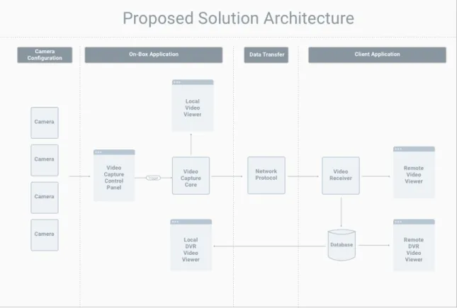
Understanding the limitations of the current model and the requirements derived
from user research, we came up with the architecture shown in Figure 2.1, which we
proposed as a viable solution to the initial problem.
The main idea is to use cameras on top of a police car, combined with computer
vision techniques, to produce a 360-degree rendering of the environment and send
that rendering as a live feed back to the police station.
There are four main aspects to the architecture: a camera configuration, an on-box
application, a data transfer avenue, and a client application. The on-box application
houses the Video Capture Control Panel, the Video Capture Core, and the Local
Video Viewers. The Video Capture Control Panel interacts with the camera
configu-ration on top of the police car to make adjustments to streaming settings. The Video
Capture Control Panel then triggers the Video Capture Core, which is responsible for
the processing and rendering of camera data to a local video viewer on the on-box
application. At the same time, that Video Capture Core sends data across some
Net-work Protocol to a Video Receiver on some hosted server. That Video Receiver then
simultaneously renders received scene data to the Remote Video Viewer and saves
that data to a hosted database, which feeds both the Remote and Local DVR Video
Viewers.
2.4
Targeted Proof-of-concept Architecture
With the proposed solution architecture in mind, we chose to break the problem down
into something more manageable that, if implemented successfully, would show that
implementing the full proposed solution would be possible.
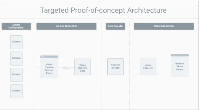
We focused on the subset of the proposed architecture, shown in Figure 2.2, for a
Figure 2.2: Architecture Targeted for Proof-of-concept
There are five core components in the targeted architecture, in addition to the
camera configuration: the Video Capture Control Panel, the Video Capture Core,
the Network Protocol, the Video Receiver, and the Remote Video Viewer. We detail
these components and the selected technologies for each in Chapter 3.
Going from the proposed solution architecture to the targeted architecture, we
left out four things: the Local Video Viewer, the Local DVR Video Viewer, the
Remote DVR Video Viewer, and the database feeding the DVR views. We pulled
those out of scope for the targeted solution based on two assumptions. First, the
Remote Video Viewer was positioned to do everything the Local Video Viewer did
in addition to handling receipt of views from a stream. So the Local Video Viewer
was just a slight simplification of what we were already implementing. Second, we
had seen evidence of streams being able to be saved to files in a database, and we
had also seen the display of videos after collection from a database. For this reason,
for our targeted architecture and focus on the parts of the solution most crucial to
solving the overall police problem.
It is important to note that there are two more big things left out of the scope of
our investigation that must be accounted for in a full solution to the police problem.
Those considerations are processing of frames and selection of a camera configuration.
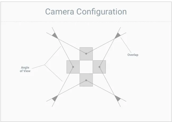
When selecting a camera configuration in a successful implementation, it is crucial
that frames from the feeds of those cameras at least touch. And it is essential that
any overlap of those cameras is then handled appropriately during processing in order
to get an accurate final panorama image. This overlap depends on camera angle of
view and distance from the objects in the scene.
The proposed architecture is designed to handle any configuration of two or more
cameras. For simplicity, we chose a four-camera configuration with four cameras at
a 90-degree angle from one another, pointing away from a point at the center of the
Figure 2.3: Camera Configuration
With that configuration chosen, we also made the assumption that our
proof-of-concept would be taking in valid input frames capable of creating a full 360-degree
Chapter 3
Technology Selection
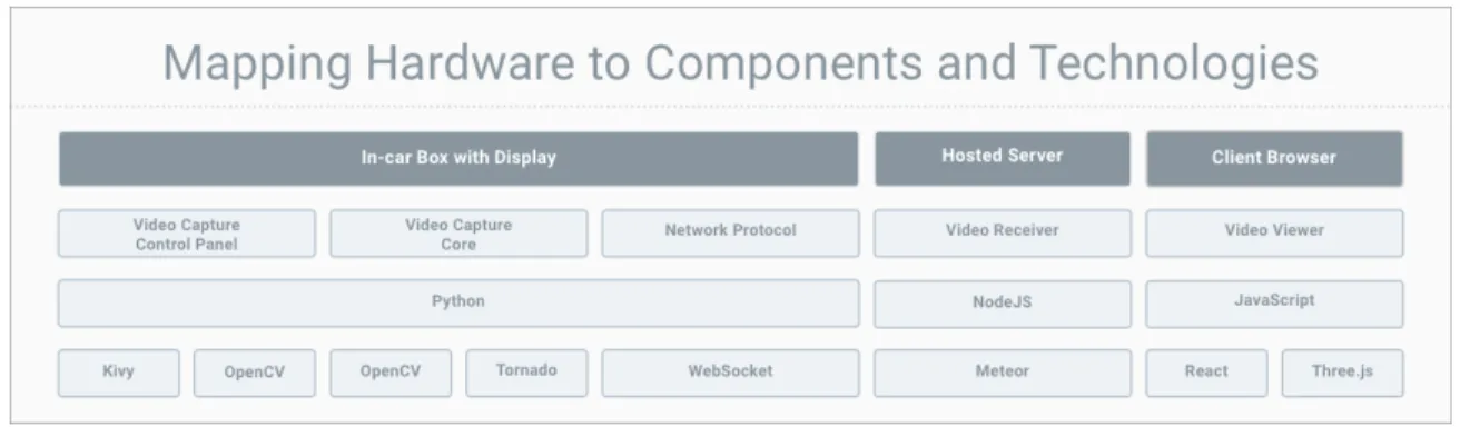
Having defined the general components of our architecture, we now map them to
technologies for implementation. Figure 3.1 shows this mapping, and the rest of this
chapter describes why we chose these technologies.
Figure 3.1: Mapping Architecture Hardware to Components and Technologies
Many of our decisions were driven by our choice of computer for the in-box
appli-cation. We chose an NVIDIA Jetson TX2 due to its powerful GPU, which we hoped
to leverage while processing frames coming in from the cameras. Some decisions were
also influenced by the experience of a team of four students that worked on the project
in the early stages of development.
With the Jetson established as our main hardware device, we next chose a
vision algorithms to use during processing. In our research, we found OpenCV, an
open source computer vision library, to be the most widely-adopted, non-proprietary
computer vision framework on the market. So we decided to base the rest of our
technology selection on enabling OpenCV to be a part of our software stack.
OpenCV has bindings in Python, C++ and a number of other languages, but its
documentation and community heavily favor Python and C++. Python does have
its downsides, including problems with performance and threading, but because of
our familiarity with Python, as well as its large set of libraries and packages and
the added benefit of a high-level language, we decided to go with it as the primary
technology in our application stack.
The next issue that needed to be addressed was how to combine camera images.
We chose cube mapping to do this and render the scene in the Video Viewer. Cube mapping is a form of environment mapping that uses the projection of a world from
a certain viewpoint to make rendered surfaces on an object appear to reflect their
surroundings [7][2], projecting the environment onto a cube. It represents a method
of getting approximately-accurate reflections on the surface of an object while saving
resources and time, and it uses significantly fewer computational resources than ray
tracing (the widely accepted, comprehensive technique for handling shadows,
reflec-tion, and refraction).
Cube mapping has a number of advantages over another widely-known method
of environment mapping,spherical mapping. Two key considerations that make cube mapping attractive are its handling of change of viewpoint and its conservation of
texture state. Cube mapping is not view dependent, so it enables dynamic change of
viewpoint. And spherical mapping stretches, compresses, and warps textures, while
cube mapping requires none of that processing and can retain the full resolution of
Cube mapping, though, does make it so you have to handle incongruity between
images at the seams of the cube. Fortunately, there are algorithms available for
compensating for this incongruity [11]. Another disadvantage of cube mapping is
that, any time the scene changes (e.g. an object or lighting element is added to the
scene or something is moving), the map must be re-rendered. But, for our purposes,
that is not an issue, and the advantages in favor of cube maps pushed us in that
direction.
We leveraged cube maps in this project to generate skyboxes that are capable of creating our sought-after 360-degree rendered environment. Skyboxes are a way of
rendering the faces of a cube around a central camera, with the camera representing
the observer’s position in space. The observer, looking out from the center of the
cube, sees the faces of the cube as if they are the background of their surroundings.
Imagine utilizing a cube map to paint a cube in space. Then add a camera to the
center of that cube and give the user the ability to move the camera and pan around
the cube. The result of this is a smooth panorama environment that can be updated
when the scene changes by re-rendering the faces of the cube.
(a) Cube Map Indexing (b) Skybox Texture Example
Figure 3.2: Relationship Between Cube Maps and Skyboxes
Figure 3.2a shows how the sides of a cube map are indexed, and Figure 3.2b shows
an example of a texture that, when mapped to a cube, would produce a realistic
We looked at other options for viewers, but did not find any good alternatives.
From that decision came the decision to use Three.js for the rendering of the cube
map, because it was in-browser and provided a well-documented, robust interface to
the WebGL graphics library. As a wrapper, Three.js does not have all of WebGL’s
features, but we decided it was sufficient for our purposes.
To be paired with Three.js, React was added to the technology stack because of its
value as an interface builder and its reactive, resource-saving properties. React was
not essential to the architecture, but was included for convenience of development.
With the Video Viewer technologies chosen, we then selected a Network Protocol.
This choice had two parts: the technology used by the Video Capture Core to host
data relay over the Network Protocol and the Network Protocol itself. The targeted
architecture focused on sending individual chunks of data over the protocol for
de-composition on the other side, as opposed to sending parts of a video file over an
RTMP stream. Because of this, we decided to use WebSocket, a familiar web
tech-nology well-positioned for recurrently relaying chunks of data over a network, as our
Network Protocol.
Based on our decision to use WebSocket, it made sense to utilize a well-documented
framework with WebSocket capabilities for the Video Capture Core. For this reason,
we chose the popular Tornado Python library which simplifies the process of hosting
and interacting with WebSockets.
For the Video Receiver, the main drivers of technology selection were efficiency and
scalability, both of which are big selling points for NodeJS. And because the specific
technology did not matter as long as it supported WebSocket message receiving,
which comes with JavaScript, we chose a new, but versatile NodeJS framework called
Meteor to build the receiver. Simliar to the choice of using React, choosing Meteor
was not essential to the architecture of the project, but it was included in the stack
The last decision that was made was the library to use for building the Video
Capture Control Panel. For this portion of the architecture, we chose a technology
called Kivy, a relatively popular Python interface builder. All we needed from this
interface builder was the ability to trigger other Python code, more specifically the
stream of data over WebSocket, from the developed interface. With this as the only
requirement, I looked for the library with the strongest community and
Chapter 4
Implementation and Analysis
With the components and associated technologies in mind, we can move on to our
implementation and the analysis of that implementation.
4.1
The Components and Their Action Segments
We can define anaction segment to be a fundamental building block in development that takes in input, produces some output, and is associated with a parent component.
From this, we can define our implementation in terms of a series of action segments,
which come together as a circuit independent of their parent components, that must
all work in conjunction to create a working proof-of-concept.
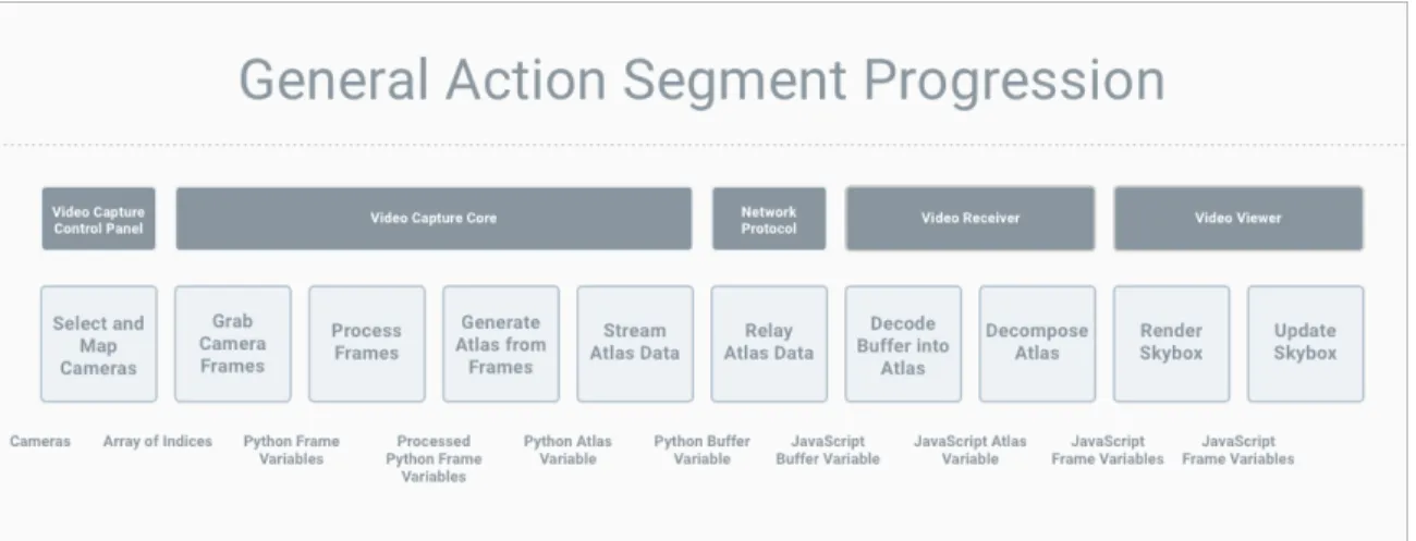
The components in our target architecture and their action segments are shown
Figure 4.1: Components and Their Corresponding Action Segments
Under the action segments in the diagram are the inputs and outputs to those
action segments. For example, an array of indices is the output of the Select and
Map Cameras action segment as well as the input to the Grab Camera Frames action
segment.
4.2
How the Action Segments Come Together
At a high level, these action segments come together to create a pipeline. First,
the Video Capture Control panel provides the user with an interface to select what
cameras, from a list of available cameras, they want to use for streaming and where
they want those cameras to map in the final rendered environment. Then, the Video
Capture Core grabs frames from the selected cameras, processes those frames so that
they will be rendered appropriately, composes those frames into a texture atlas, an image containing a collection of sub-images that are used as textures for mapping to an
object, and streams that atlas data recurrently across the Network Protocol. We can
also envision the Network Protocol as its own component, with its sole responsibility
being to relay the atlas data from the Video Capture Core to the Receiver as a buffer.
Once the Video Receiver gets information via the Network Protocol, it decodes
Capture Core. The Video Receiver is then tasked with decomposing the atlas into
six individual pieces, stored in a file-like data type, via UV mapping, a technique for breaking a single texture into a set of sub-textures. Once those individual pieces,
representing the sides of the rendered environment, are extracted from the atlas, they
are passed to the Video Viewer. The Video Viewer lastly renders those pieces to a
skybox and updates the skybox when new frames are passed from the Video Receiver.
4.3
Action Segment Breakdown and Analysis
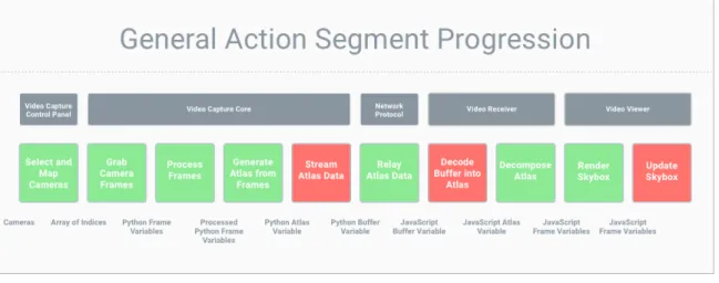
The pipeline implementation did not end with the result we were hoping for. There
were three core breaks in the progression that stifled successful implementation. Those
breaks are shown in Figure 4.2
Figure 4.2: Breaks in the Action Segment Progression
Here we break down each action segment and describe: our implementation, the
assumptions we made, whether or not our implementation worked, why we think
or know the implementation did not work if it did not, and how solutions to any
4.3.1
Select and Map Available Cameras
This is the portion of the application responsible for allowing the user to select cameras
from a set of connected camera devices and map those cameras to sides of the final
cube map. It takes in a set of camera feeds and returns an in-order array of camera
feed indices for streaming.
When a set of cameras is plugged into a host computer, for the purposes of this
project, it is imperative that the cameras are either positioned in a static manner that
is reflected in the rest of the implementation or the user is allowed to select their target
cameras and map or appoint those cameras to a direction in the final rendered
360-degree view. This action segment was deemed necessary for two reasons: 1) the use
case of being able to choose which feeds represent what part of the rendered scene was
unearthed when talking about the viability of having a flexible camera configuration
(where cameras can be added and removed in the system), and 2) because we made
the choice to use OpenCV for interfacing with cameras, there ended up being a
well-known camera indexing problem that made selecting and mapping of cameras a must.
When defining this action segment, the assumption was made that the user would
want the capability to tailor the configuration of the input cameras with software.
But that is not necessarily a valid solution in every case, especially in the case of a
police officer in the field. In that situation, the police officer may have to focus all of
his attention on the situation and therefore may require an automated configuration
process. This can be done (using image analysis to detect whether a feed is open
and valid, open and invalid, or closed) but it does become complex when looking
at a cross-platform solution, so it made sense to create an easy-to-use interface for
setting and verifying the configuration of cameras instead. Because the creation of
this action segment added value for testing, development, and possible deployment
The key requirements for this segment were: 1) selection of available cameras, and
2) mapping of the selected cameras. The assumption was that both of these could be
handled in one step with a single user interface.
The implementation of this action segment could certainly be more robust, but it
worked successfully for our purposes and gave us the output we had hoped for. We
were able to take in a set of connected cameras, make a choice between them, and
then assign the chosen cameras to a list of cameras for passing to the next action
segment, grabbing frames from cameras. This action segment worked well and was
not a roadblock to successful completion of the solution.
4.3.2
Grab Frames from Cameras
This segment of the application grabs frames from each of the cameras. It takes in an
array of camera feed indices and outputs a set of Python variables containing frame
data.
When grabbing frames, we made the assumption that the camera configuration
was a basic four-camera configuration as described in Chapter 3. We assumed that,
with that specific configuration, we would be able to take in frames and map each
frame to one side of the final cube map, leaving the tops and bottoms of the cube
blacked out. We also decided to open a unique thread for each camera feed and grab
frames from all cameras at the same time to make sure the frames synced up. We
thought this would work based on examples we found that cited grabbing from all
cameras at the same time as the best way to get synchronized frames.
Our implementation of this segment did work, and there was not significant room
for improvement worth mentioning. But it is important to note that choosing to open
4.3.3
Process Frames to be Square and Power-of-two
This action segment is responsible for processing frames to meet the requirements of
Three.js for mapping to the final cube map. This means altering the frames so that
they are both square and have length and width with a power-of-two pixel value. It
takes in a set of Python variables containing frame data and outputs Python variables
containing processed frame data.
For the processing of frames, we made the assumption that the only step we would
need for a proof-of-concept would be to convert the images to square power-of-two.
Because this was the limitation for the side of a cube map in Three.js, we made
it a priority in our implementation. We also made the decision to leave out overlap
handling during implementation to simplify our model and focus on getting processed
frames through the entire circuit.
We thought this assumption was valid because leaving out overlap handling would
still allow us to show functionality of the overall circuit, which is the main purpose
of the investigation and implementation.
Our implementation of this segment also worked as was needed, taking in the
appropriate inputs and producing the right outputs. Significant improvement could
be made by removing our assumption of good input frames and adding in the handling
of overlap between cameras in a camera configuration.
4.3.4
Compose Frames into Atlas
The next segment of the application is responsible for taking the processed frame data
and putting it into the form of a texture atlas. An atlas file was deemed necessary to
simplify the process of sending files across the Network Protocol. Instead of sending
four frames, delimited or one-by-one, across the protocol and interpreting on the other
side, it seemed easier to compose an atlas file from the processed frame data and
in Python variables containing processed frame data and outputs a single Python
variable containing the data of a generated atlas.
In composing frames into an atlas, we made the assumption that frames would be
concatenated post-processing into a straight, horizontal strip of frames. We assumed
that the orientation of the atlas and form factor of the atlas, as far as it was interpreted
correctly on the other end of the system, would be acceptable. We assumed this would
work because of existing demonstrations of both horizontal strips and T-shaped files
being used as atlases. And, because the horizontal strips take up less area that
the T-shaped files, we assumed they would be easier to stream across the Network
Protocol.
This action segment was not a blocker in the overall implementation and actually
worked quite well. No glaring flaws in implementation were evident.
4.3.5
Stream Atlas Data Across Network Protocol
This portion of the application is responsible for actually sending messages with the
atlas data over the Network Protocol. It takes in a Python variable containing the
atlas data, converts it to a buffer, and sends a message containing that buffer over
the Network Protocol.
This is where the first roadblock comes into play. In this segment, we assumed
that, to stream the atlas data across the Network Protocol, we needed to open up a
new thread to run that streaming. And this made sense based on implementations
in Tornado tutorials and examples. Very commonly WebSockets were initialized by
opening up a new Pythonic thread.
This did not work, and we think the issue arose when the control panel application
accessed the camera feeds in a new thread. Even when we could grab frames and
pro-cess them in the main thread, we could not do the same in the new streaming thread.
that it is related to the way in which Python implements threading (something that
it is well-documented as a problem and is highlighted here: http://bit.ly/2o1nmGy).
In general, concurrent programming is the making of programs that can do more
than one thing at a time, better known as multitasking [1]. The way in which a
processor runs multiple tasks depends on the availability of other processors. If there
is only one processor available, the only way running multiple tasks can occur is by
rapidly switching between them, hence the name multitasking. If other processors
are available, parallel processing can provide simultaneous task execution (speeding
up computations as a result), but if the number of tasks exceeds the number of
processors, each processor will have to multitask.
A process is an executing instance of an application. A thread is an independent
task that runs inside of a program; it is an execution path that is a component of a
process. Threads within a process share the state of their parent process as well as the
memory and address space appointed to that process. And concurrent programming
often shows itself in the form of multi-threading, where multiple tasks, or threads,
run concurrently, switching back and forth between one another inside of a process.
So, it seems we should be able to communicate between threads. But, because
Python is an interpreted language, and because of the inherent dangers of
multi-threading, Python’s interpreter is designed so that shared data cannot be accessed
simultaneously. A thing called GIL, or the Global Interpreter Lock, is put in place to make sure the interpreter follows this logic. The result: only one thread can ever be
executed at a time in a Python environment [9].
If we had known about the problem earlier, we would have been able to switch
to a technology like C++ where threading is more organic. But time created some
technology stubbornness that had us trying to make technologies do what they were
4.3.6
Relay Atlas Data to Receiver as Buffer
This segment takes the buffer from the previous step and handles delivering that
buffer to the Video Receiver. The general logistics of this segment are handled by the
WebSocket protocol. It takes in a buffer and outputs that buffer on the other side.
This portion of the application was largely hands-off and therefore did not provide
much room for improvement or optimization. After passing data to the Network
Protocol from the Video Capture Core, we were able to receive that data inside of
the Video Receiver as desired.
4.3.7
Decode Buffer from Network Protocol Back Into Atlas
This segment takes the buffer received from the WebSocket and converts it back into
a texture atlas in the form of a JavaScript variable.
This is another one of the segments that gave us more trouble than we had hoped.
For this segment, we made the assumption that we would be able to decode the buffer
from the Network Protocol back into an atlas, but we did not take into account how
to store that atlas as a variable as opposed to an actual file for consumption by the
Three.js api. So, we were not able to find a way to produce a data result capable of
being decomposed in the next segment. Though we could identify the source of this
problem, which was our choice of Three.js as our rendering technology, we could not,
due to time constraints, come up with a way to craft a solution to the problem.
This was one of our core blockers, and it came largely out of technology
stubborn-ness due to time constraints, resulting in attempts to make technologies do what they
were not originally designed to do. Instead of using Three.js, a limited wrapper, we
probably should have been using WebGL or the even lower-level OpenGL to render
4.3.8
Decompose Atlas into Six Individual Frames Via UV
Mapping
This is the portion of the application that takes the atlas data and decomposes it
into six individual pieces of data representing the original processed frames. It uses
UV Mapping to break up the atlas into its component images and save those images
to their own JavaScript variables.
For this segment, we made the assumption that we would be able to take the atlas
decoded from the buffer passed via the Network Protocol and break it into individual
frames for rendering in the skybox. And, we thought this was reasonable because we
had seen the rendering of of a skybox from an atlas file before. So we went through
implementation and found that our assumptions were correct, and we were able to
produce our intended result without significant need for improvement.
That said, we did find toward the end of the project that this action segment could
potentially be skipped, rendering a cube map from a single combined texture. This
would mean we could strip the segment from our implementation and significantly
simplify the overall solution.
4.3.9
Render Frames to Skybox
This part of the application renders the 360-degree scene described by the original
camera frames. It generates a skybox by defining a scene, camera, and renderer, and
it then adds a cube map to the scene with a camera at the center of that cube. It
takes in six JavaScript variables containing frame data to output this rendered scene.
During design of this segment, we made the assumptions that frames decomposed
from the atlas would be able to be used for mapping to the cube map, and that
we could then easily create a skybox from that cube map by rendering a scene and
We made these assumptions based on the relative ease we experienced of rendering
cube maps from a set of six local files. But we did not make the distinction between
the Three.js api’s loading of a cube map from six local files and using that same api
with JavaScript variables made up of frame data (similar to the problem found in
Subsection 4.3.7. This was a big problem that we were fortunately able to avoid by
using UV mapping to produce a single, encompassing texture that we could apply to
the cubes, rather than relying on the interpretation of several textures.
Though this segment did not work exactly as planned, we were able to manipulate
it to give us the right results from the right input.
4.3.10
Update Skybox When New Frames Are Available
This final segment takes the skybox already rendered in the previous segment and
updates that skybox with new frame data as it comes in from the Video Capture Core.
Similar to the previous segment, it takes in six JavaScript variables containing frame
data and outputs a rendered scene. But, in this case, it does not have to re-define
the renderer and re-render the entire scene.
After successfully rendering frames to the skybox from an atlas file, the assumption
was that updating the skybox would be as easy as writing a couple of lines of code
telling the cube map to take in new texture data decomposed from the WebSocket and
update the rendering of the skybox based on that new data. And, we were confident
that this assumption was going to be valid after being able to update a cube map by
repeatedly changing local files (one for each side of the cube map) feeding textures
to the cube map. But it turns out this assumption as not correct.
Unfortunately this ended up being a major blocker in the action segment
progres-sion, and we do not really understand why updating of the textures in the cube map
was not working. This break seemed to occur after adding decomposition of the atlas
tex-tures in the cube map, a solution to this problem exists. Lack of time to investigate
the problem, as it came up at the end of project completion, and lack of expertise in
Three.js might have limited our ability to eliminate this obstacle. Either way, we
re-alized that we probably should have been using WebGL or OpenGL directly, instead
of operating at the wrapper level, to make sure we had all of the functionality and
Chapter 5
Discussion and Conclusion
5.1
Summary of Results
In the end, there are three core complications that limited our ability to produce
a proof-of-concept for the solution to the initial police problem: Python threading
problems when streaming atlas data, decoding our buffer from WebSocket into a
form readable by the Three.js api, and lack of functionality (as well as technology
stubbornness) in our use of Three.js. That said, based on our investigation into those
complications, we feel that, with additional time and resources, the complications
could be overcome and produce the result we were looking to obtain in the first place.
For this reason, I think it is worth pursuing this project further to resolve the issues
in the current implementation and develop the remainder of the components outlined
in the full proposed solution.
5.2
Implications of Research
I do not think that our inability to get a complete, working proof-of-concept is as
discouraging as it may seem on the surface. Because we have seen effective
significant promise for getting a working overall solution that can be applied to the
police problem and a number of other potential environments (e.g. military and
in-telligence engagements). With a team of more experienced individuals, I think the
proposed solution architecture has a real possibility of working and adding value.
5.3
Lessons Learned
When going through our analysis, we realized that a number of the problems we
ran into came out of our technology selection and, due to time constraints, an
un-willingness or stubbornness to adjust technologies used in the implementation. For
example, running into our threading problem, we probably should have made the
switch to C++. But, with the time allowed, we instead ended up trying to make
technologies do what they were not originally supposed to do. The biggest
exam-ples of this stubbornness were our attachment to Python and Three.js. Three.js was
a terrific interface, but it was a wrapper to WebGL, and it therefore had limited
functionality. Instead of using this wrapper, we probably should have used WebGL
itself.
One of the biggest challenges for this project was the massive learning curve I
faced coming in with no computer vision background and a limited understanding of
photography and hardware concepts. If that background had been in place, I think
this project would have been completed successfully (with processing of overlap) in
the allotted time. Along those same lines, I think that a large part of the time
constraints at the end of the project come from getting a late start on the project in
the beginning. This put a lot of pressure on us going into the final stretch.
One last thing I learned from this project was the idea of testing the individual
components of a project before trying to combine all of the pieces together. I
at a time. But it probably would have been more wise to take each piece, make sure
it worked on its own, and then combine it into a solution. This is sometimes referred
to as spiking, and it would have been valuable if applied to each action segment.
That way, we could clarify that inputs and outputs were working with each of our
selected technologies rather than running into problems at the end that came largely
Appendix A
Codebase and Documentation
Code for this project can be found hosted at:
Front End https://github.com/LukeJFernandez/frontthesis
Back End https://github.com/LukeJFernandez/backthesis
Documentation of the code can also be found hosted at:
Front End https://lukejfernandez.github.io/frontthesis/
Back End https://lukejfernandez.github.io/backthesis/
And a demonstration of the front end code of this thesis can be found hosted at:
Bibliography
[1] D. Beazley. An introduction to python concurrency. 2010.
[2] J.F. Blinn and M.E. Newell. Texture and Reflection in Computer Generated Images. Communications of the ACM, 19(10):542–547, October 1976.
[3] Arieee Wikimedia Commons. Skybox example. 2011.
[4] Microwerx Wikimedia Commons. Cube map. 2016.
[5] Elvia. Can 1080p ip security cameras be enough for identification of license plate and people? Technical report, reolink, 2016.
[6] J. Farneman. 360 degree surveillance system and method. 2006.
[7] N. Greene. Environment Mapping and Other Applications of World Projections.
IEEE Computer Graphics and Applications, 6(11):21–29, November 1986. [8] S. Hatfield, L. Yeager, and H. Young. Stitchd. Technical report, Texas A&M
University, 2012.
[9] J. Knupp. Python’s hardest problem. Technical report, 2012.
[10] U. Neumann, T. Pintaric, and A. Rizzo. Immersive panoramic video. MULTIME-DIA ’00 Proceedings of the eighth ACM international conference on Multimedia, 2000.
[11] R. Szeliski. Image alignment and stitching: A tutorial. Technical report, Mi-crosoft Research, 2004.
![Figure 3.2a shows how the sides of a cube map are indexed, and Figure 3.2b shows an example of a texture that, when mapped to a cube, would produce a realistic skybox [3] [4].](https://thumb-us.123doks.com/thumbv2/123dok_us/8331603.2210340/21.918.202.731.695.923/figure-indexed-figure-example-texture-mapped-produce-realistic.webp)