Sponsors:
Dr. Andrew Davol
Dr. Jacques Belanger
Authors
:
Chris Ewert
Jason Kehl
Donald Syracuse
Justin Syracuse
Contact
:
[email protected]
Date of Publication
:
6/4/2020
Mechanical Engineering Department
California Polytechnic State University
San Luis Obispo
2019
i
Statement of Disclaimer
ii
Abstract
iii
Table of Contents
1.0 Introduction…..…………..……….…….………1
2.0 Background……….2
2.1 Sponsor Meetings………..2
2.2 Problem with Existing Design………2
2.3 Existing Designs of Mounting Systems and Methods………..3
2.4 Relevant Technical Literature……….……….4
2.5 Industry Codes, Standards, and Regulations………..………5
3.0 Objectives……….5
3.1 Problem Statement………..5
3.2 Boundary Diagram………6
3.3 Customer Wants and Needs………..6
3.4 Quality Function Deployment (QFD) Process.………7
3.5 Engineering Specifications……….……….7
4.0 Concept Design……….9
4.1 Ideation Process and Initial Ideas………..9
4.2 Final Design Selection……..………..11
4.3 Support Frame…..………..13
4.4 Rotating Bar………..………13
4.5 Mounting Brackets………14
4.6 Gearbox and Crank………...14
4.7 Analysis and Testing……….14
4.8 Safety Concerns………..15
5.0 Final Design………..16
5.1 Support Frame………..16 5.2 Rotating Bar………17
5.3 Mounting Brackets……….18
5.4 Gearbox and Crank………18
5.5 Maintenance and Repair………19
5.6 Cost Analysis………..20 6.0 Manufacturing Plan………20 6.1 Procurement………..20 6.2 Manufacturing………..20 6.3 Assembly………..21 7.0 Design Verification Plan………..21
8.0 Project Management.………23
8.1 Key Deliverables and Timeline……….……….24
9.0 Planned Development …...24
iv
9.2 Rotating Bar Work Done……….26
9.3 Mounting Brackets Work Done.………26
9.4 Gearbox Work Done.……….26
9.5 Support Beams Work Done..………27
9.6 A-Frame Work To Be Done………27
9.7 Rotating Bar Work To Be Done...………..28
9.8 Mounting Brackets Work To Be Done.………..28
9.9 Gearbox Work To Be Done.………..28
9.10 Supporting Beams Work To Be Done..………29
9.11 Welding Steps.……….29
10.0 Test Plan…...30
10.1 Operators Manual……….32
11.0 Conclusion……….32
References……….25
Appendix A: QFD House of Quality Table………..…A-1
v
List of Figures
Figure 1: Pre-existing Mount on top of Engineering 13.……….……….3
Figure 2: Side Pole Mount Design with Dual Panels…..……….………3
Figure 3: Top Pole Mount with Multiple Panels Fastened to It………4
Figure 4: Adjustable Solar Panel Mounting Bracket………4
Figure 5: Boundary Diagram………..……….6
Figure 6: Ideation Process…………..……….……..10
Figure 7: Isometric CAD of Initial Design Concept……….……….……..12 Figure 8: Structural Prototype……….15
Figure 9: Isometric CAD Final Design………..16 Figure 10: Isometric CAD Frame……….………..16
Figure 11: Isometric CAD Final Design………..17 Figure 12: Isometric CAD Mounting Brackets………..18 Figure 13: Isometric CAD Gearbox and Crank………..19 Figure 14: Structural Prototype – Gearbox Subsystem………..22
Figure 15: Design Process Timeline………..………..23
Figure 16: Cutting the Hollow Steel Tubing for the A-frame Legs Using A Portable Band Saw ….25 Figure 17: Cutting the Angles for the A-frame Leg Using an Abrasive Cutting Saw………25
Figure 18: Water Jet on Gear Box Frame and Base Plates for the Caster Wheels………..26
Figure 19: Drill Press Widening the Holes on the T-joints For Larger Bolts to Fasten the Support Bars to the A-frame………….………..27
vi
vii
List of Tables
Table 1: Customer Wants and Needs……….………….……….6
Table 2: Engineering Specifications Table……….……….7
Table 3: Top Six Final Design Ideas……….……….11
Table 4: Final Decision Matrix Used for Final Design Concept………..12
Table 5: Estimated cost per Subsystem……….20
Table 6: Key Deliverables and Timeline……….………24
1
1.0 Introduction
Our team consists of Chris Ewert, Jason Kehl, Donald Syracuse, and Justin Syracuse. We are four mechanical engineering students at California Polytechnic State University (Cal Poly) working on a project to benefit the Mechanical Engineering Department (ME). The intent is to design and construct an adjustable solar panel mount that demonstrates solar energy production and efficiency for the new Energy Resources concentration. This project will serve as both an educational tool for student engineers and help in the ongoing solar energy research performed at Cal Poly.
The sponsors for this project are two engineering professors, Dr. Andrew Davol and Dr. Jacques Belanger. Their intent for the design is to have a simple system that will be manually operated so they can move and/or angle the cells to a desired location and position. Their hope for this project is to utilize this system to demonstrate efficiency and output of photovoltaic systems to students in the new Energy Resources concentration.
The current panel mount consists of four solar thermal collectors mounted to a rigid system on top of the civil and mechanical engineering building located on the northwest corner of Cal
Poly’s campus (we will refer to it as Engineering 13). The collectors are non-operational,
cumbersome, and cannot be adjusted. Dr. Davol and Dr. Belanger need a new system that is adjustable and can accommodate different sized photovoltaic panels. The mount will be located on the solar balcony of Engineering 13 and implemented into the renewable energy micro-grid.
The background addresses the current mount for the solar panels on Engineering 13, along with market designs and technical literature pertaining to solar panel mounts. The objectives section
begins with the sponsor’s desired needs, wants, and the engineering specifications set as a
result. The most important specifications are described in detail to ensure that the solution meets these requirements.
The design will consist of four components, each one being necessary to ensure a successful design. The ideation process for each component is described in detail and initial concept models are provided to present various solution paths. Utilizing a morph matrix, we constructed six completed, feasible designs. These six designs were then analyzed against a weighted decision matrix to arrive at the selected sawhorse design.
Preliminary calculations using known panel weights and predicted wind provide proof of concept. Also, potential challenges and safety concerns moving forward were mitigated using failure modes and effects analysis. A manufacturing plan was created to provide clarity for unfamiliar technicians to assist in the assembly of the design. Each subassembly was broken down to allow for a consistent purchasing of parts in our cost analysis.
2
which will allow for the ability to assemble or dissemble the mount safely and efficiently to transport or relocate it to a desired location.
2.0 Background
This section consists of sponsor meetings, interviews, existing designs, relevant journal articles, and building codes/regulations to provide references to previous material and requirements to ensure our design is up to industry standards and regulations. Initially, it was mentioned that we would be looking into processing and displaying the output of the panels, we have now narrowed down our project to just building and designing the solar panel mount.
2.1 Sponsor Meetings
Two meetings were conducted with Dr. Davol, it was concluded that the purpose of this project is to design an adjustable fixed angle mount that can hold multiple photovoltaic1 (PV) panels of
different sizes for research purposes in the Cal Poly ME department. The mount must have the means to hold two large Sunmodule Plus SWA 295 mono photovoltaic cells and should have the ability to adjust to hold three medium sized panels. The panels will be interchangeable
depending on the research or demonstration that our sponsors will be conducting. A single person must be able to change out the solar panels without the assistance of a second party. Wheels will be implemented on the mount so that it can be relocated to a different location but will remain on the solar balcony of Engineering 13. This has changed from the initial Scope of Work due to a lack of clarity in the design. Initially, it was interpreted that an electronic display system was required for the project but was later concluded that the focus will be geared towards the mount primarily.
2.2 Problems with Existing Design
The current mount locating on the Engineering 13 balcony is non-operational and mounted on a very large and rigid system. This mount cannot be adjusted nor can be moved in any direction. Most of the time, fixed solar panels are efficient enough that they do not need to be angled toward the sun; however, the current system has the face of the panels pointing slightly east of due south. In the northern hemisphere, it is optimal to face your solar panels south as it
orients the sun’s rays more perpendicular to the surface of the panel (the closer the sun rays
are to perpendicular, the higher the efficiency). Furthermore, the panels themselves are in a very poor location as there is a large eucalyptus tree that shades the panels during most of the day.
3
2.3 Existing Designs of Mounting Systems and Methods
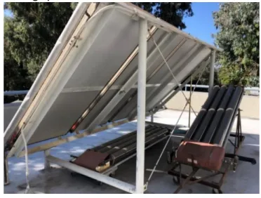
Figure 1 is the pre-existing fixed solar mount located on top of Engineering 13. The system has
never been used over a 25+ year time span. The old mount holds four large 8’ x 3’ PV thermal
panels that cannot be replaced easily or relocated. The location of the fixed structure can only be used with the approval of Cal Poly because there are giant eucalyptus trees that shadow the panels at the peak times of the day. Currently, it seems more reasonable to rebuild/purchase a new mount that is not already fixed because Cal Poly may not approve of the tree's removal. For these reasons the existing system was not used.
Figure 1: Pre-existing mount on top of Engineering 13.
Figure 2 shows a side pole mounting system that can support a wide range of heavy-duty side pole solar structures. The design could hold 1-4 module panels depending on the required application. It can withstand wind speeds of up to 130 mph and the material of the mount is made of high strength stainless steel band clamps, U-bolts, and custom parts that can fasten the panels to the mounts. The tilt angles of this structure range from 30 to 90 degrees and support up to 1000W on a single structure [1]. This is an optimal structure design that could help us with adjustability for the angle portion of the design.
4
Figure 3 consists of a top pole mounting system that holds between 1-24 module panels. Depending on the location of assembly, the total area of these panels can add up to 260 ft2
.
Installation of these panels is considerably easier than other mount frames, but it does not have the ability to hold universal panels. The tilt angle for this design ranges from 15-60 degrees, can sustain wind loads up to 90 mph, and can support a power output of 4.1kW on a single pole mount [2]. This structure is optimal for a similar design, if more power output was necessary for the device.
Figure 3: Top pole mount with multiple panels fastened to it [2].
Figure 4 is an image of an adjustable solar panel mounting bracket made from rust free aluminum with stainless steel hardware. This design can tilt with small holes and peg application along rail lines for single person adjustability. The mounts maximum panel application width is 500-550mm with most mounted panels being 100W and 12V output. The tilt angle ranges from 0-90 degrees [3]. The mechanism used to adjust the angle is a common application used for positioning purposes.
Figure 4: Adjustable solar panel mounting bracket [3].
2.4 Relevant Technical literature
5
better understanding of the rotation methods utilized. Nader Barsoum of Curtin University fabricated a dual axis tracking system in 2011 [8].Sections three and four of the articles discuss the physical mounting system and moments associated with the panel mass and wind forces. We have utilized this analysis and conducted similar calculations of our design. Further, Barsoum explains the use of pillow block bearings for both azimuth2 and tilt3 adjustability. This
is a proven solution that we can utilize in our design. Our second relevant academic article comes from the Saddam University for Engineering and Science [9]. Al-Naima and Yaghobian designed a dual-axis tracking system for research purposes in 1990. The article offers great insights into solar coordinate systems, mounting design, and steel frame analysis. Sections two, three, and four all pertain to our scope while later sections detailing the automated tracking system do not. We have adapted their coordinate system and utilized it when designing for azimuth and tilt adjustability.
2.5 Industry Codes, Standards, and Regulations
Given our design will be used in primarily one location, the industry codes and standards will not significantly limit this design. Design safety is still a priority for the mounting system and current codes are implemented to ensure user safety. Three codes were considered in our design: the first is Title 24, Part 2.5: California Residential Code [10]. This ensures that the mount does not exceed building height limits. Second, is Title 24, Part 4: California Mechanical Codes [10] Part 4 requires safety from bodily injury while operating on and replacing solar panels on the mount. Finally, Title 24, Part 9: California Fire Code Regulation [10]. Part 9 mandates that the mount does not block fire exits or emergency evacuation routes.
3.0 Objectives
The objectives section of this report outlines the problem statement and design requirements. These are derived from sponsor meetings, the Quality Function Deployment process, and engineering judgement. Since Preliminary Design Review, we have re-evaluated a few of our engineering specifications. The main specification altered was the overall weight of the design, increased from 100 lbs. to 350 lbs.
3.1 Problem Statement
Cal Poly’s new Energy Resources concentration needs a way to inspire and educate students
about various renewable energy sources through their micro-grid. We aim to design and build a new solar panel mount capable of holding multiple photovoltaic panels that can be interchanged, so that the instructors can demonstrate efficiency and power output of an adjustable system. This mount will also allow for expanded solar energy research to be done at Cal Poly.
6 3.2 Boundary Diagram
Figure 5 shows the current boundary diagram. Boundary diagrams illustrate the systems assembly and components within the project that will be implemented into the final design. We have selectively chosen the base of the photovoltaic panels as it will be an important sizing factor to how the panels will be attached to the mount. The base of the mount has been incorporated along with the mount and the information needed to properly secure the system to the surface.
Figure 5: Boundary Diagram
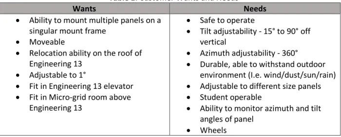
3.3 Customer Wants and Needs
Through meetings with ME faculty and understanding Cal Poly ME students, a list of wants and needs was determined. Needs are classified as necessary requirements for basic mounting function. Wants are classified as stretch goals, but not required within our scope.
Table 1: Customer Wants and Needs
Wants Needs
• Ability to mount multiple panels on a singular mount frame
• Moveable
• Relocation ability on the roof of Engineering 13
• Adjustable to 1°
• Fit in Engineering 13 elevator • Fit in Micro-grid room above
Engineering 13
• Safe to operate
• Tilt adjustability - 15° to 90° off vertical
• Azimuth adjustability - 360°
• Durable, able to withstand outdoor environment (I.e. wind/dust/sun/rain) • Adjustable to different size panels • Student operable
• Ability to monitor azimuth and tilt angles of panel
7
Note: Tilt and Azimuth angle specifications have been added to the needs for the project. Size constraints due to the Engineering 13 elevator and the Engineering 13 micro-grid room have been added to the wants. Wheels have been moved from a want to a need as they provide azimuth adjustability and general relocation convenience.
3.4 Quality Function Deployment (QFD) Process
The Quality Function Deployment (QFD) process allows for a deeper understanding of the
customer’s problem. This method was developed to help determine specifications based upon
the customers concerns and input. By spending time and energy in empathizing with the customer and getting to the root of the problem, we are better prepared to design a solution that will satisfy their need. We utilized a house of quality worksheet (Appendix A) to turn customer needs into engineering specifications. This helped prioritize customer needs, conduct market research into existing solutions, and set design goals for later in the design process.
From the QFD, safety and ease of use were established as top priorities when it came to operation of the device. As ethical engineers the design selected must consider all safety constraints. Safety concerns will be a top priority since there will be large swinging panels. Ease of use is necessary because the instructors would appreciate the ability to change the parameters of the system without the help of another person. Complete adjustment of the solar panels should take no longer than five minutes.
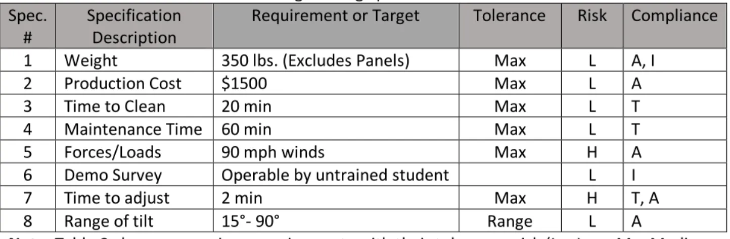
3.5 Engineering Specifications
The Engineering Specifications Table, shown in Table 2, quantifies specific qualifications to meet design requirements. These specifications are derived from needs by the customer. The requirement or target is derived using engineering judgement and the QFD process.
Table 2: Engineering Specifications Table Spec.
#
Specification Description
Requirement or Target Tolerance Risk Compliance
1 Weight 350 lbs. (Excludes Panels) Max L A, I
2 Production Cost $1500 Max L A
3 Time to Clean 20 min Max L T
4 Maintenance Time 60 min Max L T
5 Forces/Loads 90 mph winds Max H A
6 Demo Survey Operable by untrained student L I
7 Time to adjust 2 min Max H T, A
8 Range of tilt 15°- 90° Range L A
Note: Table 2 shows our various requirements with their tolerance, risk (L = Low, M = Medium, H = High), and compliance (A = Analysis, T = Test, S = Similarity, I = Inspection).
8
The requirement or target is further explained for clarity purposes:
1. Weight
The overall weight of the solar mount is important to consider because of possible tipping hazards and ensuring the mount can be moved or relocated when needed. The weight test will be conducted by taking the final model and placing the mount on the large blue digital scale that has a capacity of 1000 lbs. located in the Cal Poly Engines Lab. The weight requirement of the system has been changed to a maximum of 350 lbs. due to the size requirement and the necessity to support various loads without damaging the design. It was also concluded that weight is of lesser importance since the system will not be moved while in full assembly.
2. Production Cost
Our Bill of Materials has outlined the price per component for all purchased and machined part. This allows us to keep close track of the budget and ensure efficient spending of resources. The assembly of this mount will be conducted in the Cal Poly shops to significantly reduce labor costs.
3. Time to Clean
The user will be timed while wiping off the mount and solar panels after the design has been exposed to the outdoor conditions. It must not take this individual longer than 20 minutes to clean the entire project. This will be tested after completion of manufacturing.
4. Maintenance Time
The amount of time it takes to replace one of the panels on the mount without the use of a second party. Upon user feedback, it was reasonable to expect a team of two or three people to perform panel replacement. This task should take no longer than 60 minutes to conduct. This will be tested after completion of manufacturing.
5. Forces/Loads
Hand calculations and finite element analysis (FEA) have predicted how the mount will react under certain forces, loads, and design constraints. The most extreme case predicted was a maximum wind speed of 90 mph. It was shown that while not ideal for accurate operation, the mount and panels will remain upright and deflections will not permanently damage any component. Engineering analysis will be confirmed with inspection upon completion of manufacturing.
6. Demo Survey
9 7. Time to Adjust
This specification is strictly for the user to make sure that it doesn’t take them to long to change the position of the panels. Both azimuth and tilt angles were considered to capture multiple different data values at different times of day. This will be tested upon completion of manufacturing.
8. Range of Tilt
This specification is the amount of rotation that the panel will point toward the sun to allow the mount to capture the maximum amount of sunlight. This will be tested after completion of manufacturing.
The engineering specifications deemed as “high risk” are specifications which will be most
difficult to accomplish. These specifications were the primary focus during the design phase of the project.
1. Forces/Loads
Force and load requirement are considered a high-risk specification due to our design's safety and dependability need. Safety is our highest priority, reflected in our house of quality QFD process. Through both engineering analysis during the design process and visual inspection upon completion of manufacturing, we can ensure a safe solution.
2. Time to Adjust
Another highly weighted need for the design is the ability to easily and quickly adjust the azimuth and tilt of the panels. Our gear box will allow the user to rapidly and accurately adjust tilt while caster wheels allow for azimuth angle adjustment.
4.0 Concept Design
To proceed with a chosen solution, many design selection tools were utilized, such as functional decomposition, Pugh matrices, and a weighted decision matrix. These tools provide justification for the chosen design path and ensure consideration of all design ideas.
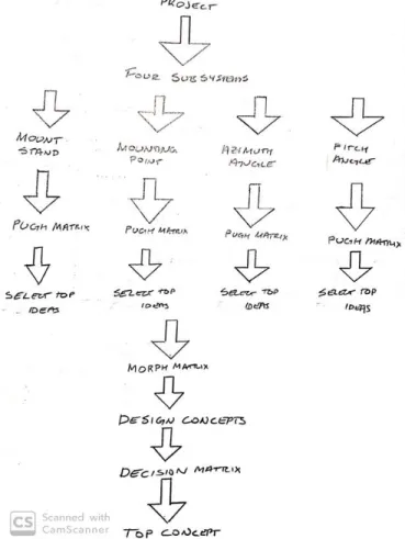
4.1 Ideation Process and Initial Ideas
The ideation process began by specifying exactly what was needed to meet our requirements. After analyzing basic needs and wants provided by the user, four basic components were established that when combined would create a successful design. The four main components consist of a structural frame, a method to adjust azimuth angle, a method to adjust tilt angle, and a system that would adjust to hold various panel sizes.
10
example of the brainwriting process for the panel mounting feature. Brainstorming is a common ideation method where team members rapidly contribute ideas through open dialogue. These two ideation techniques were repeated for each function and resulted in the initial list of ideas referenced in Appendix B.
After reviewing our initial ideas, a few designs were selected from each component pool based on what was deemed feasible and effective. These designs were put through a Pugh matrix (Appendix B) to determine the best couple designs for the given function. Pugh matrices compare ideas generated in brainstorming to a datum. We chose to compare our ideas to the current stationary mount located on the solar balcony of Engineering 13. After selecting the best few designs for each function, a morph matrix (Appendix B) was utilized to generate six completed designs. The morph matrix allows functional ideas generated in brainstorming to be combined in various ways. This allows the best features to be applied across different designs.
The top six designs advanced into the final selection process. Figure 6 provides a visual representation of the process exercised to reach our top six concept solutions.
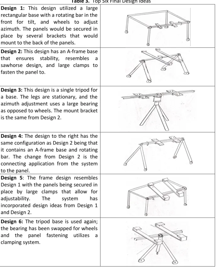
11 4.2 Final Design Selection
The top six designs shown in Table 3 were constructed based upon the top designs that came out of our Pugh matrices. Nine total components were selected from the Pugh matrices. Three stands, two changes in tilt angle, two changes in azimuth angle and two methods of mounting.
Table 3. Top Six Final Design Ideas Design 1: This design utilized a large
rectangular base with a rotating bar in the front for tilt, and wheels to adjust azimuth. The panels would be secured in place by several brackets that would mount to the back of the panels.
Design 2: This design has an A-frame base that ensures stability, resembles a sawhorse design, and large clamps to fasten the panel to.
Design 3: This design is a single tripod for a base. The legs are stationary, and the azimuth adjustment uses a large bearing as opposed to wheels. The mount bracket is the same from Design 2.
Design 4: The design to the right has the same configuration as Design 2 being that it contains an A-frame base and rotating bar. The change from Design 2 is the connecting application from the system to the panel.
Design 5: The frame design resembles Design 1 with the panels being secured in place by large clamps that allow for adjustability. The system has incorporated design ideas from Design 1 and Design 2.
12
The six designs were then put through a decision matrix to establish a final design. We chose 11 factors referencing the House of Quality and Pugh matrices as they were still important to consider. Ease of use, ease of adjustment, and range of motion has been added at this stage since the Scope of Work. The weighted scale represents how important each factor is with one being least important and five being very important. Next, each design is ranked from 1-3, three
being the design accomplishes the factor very well, and a one being the design doesn’t
accomplish the factor at all. Once ranked, the score is multiplied by the weight, then added together to determine the top design.
Table 4. Final decision matrix used to select final design concept Decision Matrix
Factors Weighted Scale
Cost 1 1 1 2 2 1 1
Reliability 4 2 1 2 3 1 2
Manufacture 3 1 2 1 2 1 1
Weight 3 2 1 3 2 1 2
Aesthetic 2 2 1 3 3 2 3
Ease of Assembly 4 2 2 1 2 2 1
Ease of Adjustment 5 3 2 3 3 2 2
Range of Motion 5 3 1 2 3 1 2
Durability 3 2 3 1 2 3 1
Mobility 5 3 2 1 2 2 3
Total 81 58 65 86 57 66
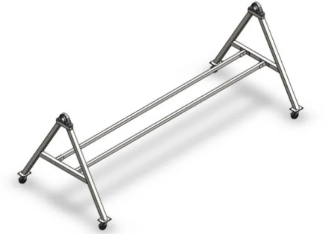
Our team agrees with the decision matrix that the sawhorse design would best fit the project requirements. This design scored well across all factors and can be manufactured within the timeframe of this project. A simplified CAD model was created for better understanding of design size and shape shown in Figure 7. The model also provides an idea of panel size relative to the mounting mechanism. The mounting system has been broken-down into four critical subsystems: the support frame, the rotating bar, the brackets and the gearbox/crank system.
13 4.3 Support Frame
From the Pugh matrix and design matrix, the best support frame mimicked that of a sawhorse. This helped us limit material usage as the top converges at a single point where the panels rotate about. As shown in Figure 7, the support frame consists of two A-frame designs with a connecting bar in the middle. Although the system would stand without the long bar connecting the two, it was found during prototyping that it gave necessary support while moving the design, as the rotating bar would deflect without it. To rotate and move the system, caster wheels4 will be placed on the bottom of the A-frame. This will also be the mechanism to
rotate the azimuth. To mount the rotating bar, two bearing holders will be manufactured and mounted at the tip of each A-frame.
Size: It was established that the height would need to be a minimum of 3.3 feet off the ground to clear the largest panels. For stability reasons a large base was desired, and an interior angle of 60° was chosen. This required that the leg of the A-frame be at least 3.8 feet. For clearance and the sake of working in round numbers, a final length of four feet was decided upon.
Material: We have decided that Aluminum bar would be the best material to construct the support. Although it has less strength than steel, the maximum weight of the system will be considerably lower with aluminum. As well, since the design will be outside much of its life, the aluminum will corrode at a much slower rate than other materials.
Manufacturing: The aluminum bars will be cut to length and welded together, the bearing holders will be machined, and then welded to the top of the A-frame.
Concerns: Aluminum is very difficult to weld and would either require significant practice or professional assistance. We will consider asking Kevin Williams, the Cal Poly welding instructor, to help us with this task. Furthermore, the bearing holder will take significant time to manufacture and some form of protection from the elements will need to be designed for the bearings.
4.4 Rotating Bar
The rotating bar provides a method of adjusting the tilt of the panels. It will be supported on both ends by bearings with a few inches extruding through one of the bearings to provide a location for the gearing/crank system used, which will be explained in greater detail in section 4.6.
Size: A square bar approximately 10 feet in length will be needed to hold the panels. The length was determined by the width of each of the panels (three feet a piece). The clearance between each panel and the bearing holders will be approximately one inch. The square cross-section was determined by the mounting method. A bracket on a circular cross-section rod may not provide enough clamping force to keep the panel from slipping on the rotating bar. The square bar design eliminates that possibility. Material: The optimal material will likely be steel as it is weather resistance and has high strength.
14
Manufacturing: Stock material will include a foot square hollow bar, and two 10-inch solid rectangular bars. The solid bars can be turned down on one side into a circular cross section. The square end can be inserted into the hollow square bar, and then welded together to act as an adaptor piece with the circular end being inserted into the bearing.
Concerns: Using a steel bar will be very heavy. A 1”x1”x10’, 1/8” thick bar weighs about 35lb. This, along with the weight of the panels, will add to the deflection of the bar. The more the bar deflects, the more difficult it will be to change the tilt angle leading to a shorter lifespan on the bar.
4.5 Mounting Brackets
Separate brackets will be machined to configure with residential and commercial panels. The bracket will be fastened to the panel using the preexisting bolts in the corners of the panel. Then four holes on the horizontal member of the bracket will line up with holes on the rotating bar to complete the mounting system.
Material: The bracket will be made of aluminum.
Manufacturing: The bracket dimensions will correspond with panel dimensions. Then, the vertical components of the bracket will be welded to the horizontal components. Finally, four holes in the horizontal and four holes in the corners need to be drilled. Concerns: Bolt shearing will be analyzed and tested; however, this is not expected to be an issue with the panels being loaded on the rotating bar at their center of mass.
4.6 Gearbox and Crank
A gear system will be implemented to precisely adjust the tilt of the panels. It will require a high gearing ratio such that the bar moves in small increments for each turn of the hand crank. The hand crank will be able to lock at several points using a pin on the crank and hole on the frame, thus locking the entire mechanism. The hand crank will be locked every quarter turn which will correspond to a single degree change on the panel.
Size: The ratio will be very large and could consist of two or three gears. This will allow for accurate tilt angles. Gear size will dictate the overall configuration of the gearbox housing.
Materials: Premade steel gears will be used with aluminum housing.
Manufacturing: Components will be purchased off the shelf and then assembled.
Concerns: We are now adding a system that will need to be lubricated and requires high tolerance fitting. It will be time consuming and difficult to manufacture.
4.7 Analysis and Testing
To prototype our design, we constructed the supports and bearing holders out of 2” x 4” wood
15
Figure 8: Structural Prototype
As stated in section 4.3, when moving the mount, the supports would separate from each other and the PVC pipe would deflect. To solve this, we added the connecting bar at the base. This solved the deflection issue but now limits our range of motion. Fortunately, our tilt angle requirements were between 15°-90° and the added bar now limits it from 5° to 175°. Furthermore, it was discovered that the bearing holders and our method of mounting them would act as a weak point in our system. To correct for this, we decided that manufacturing our own holder and welding it to the final design will be our best option.
To better understand the loads we are working with, a free body diagram was drawn of the support to obtain a better understand how the loads would be distributed, for reference see Appendix C. Given the size of the panels, each leg of the system will not need to hold greater than 100 lbs. This calculation will also dictate the size of caster wheels necessary.
Under full loading, strain analysis determined the beam would deflect 1.75” at the center of the rotating bar if it is made of solid 1” x 1” steel. This is unacceptable, so we looked at increasing the size of the beam to 1.5” x 1.5”. This reduced the deflection to .88”, which is still far too
great. At 2” x 2”, the deflection is only .43”, which is more acceptable, but the weight of the bar
would be considerably large at that point. We will continue to look for a proper medium. Calculations can be viewed in Appendix C.
4.8 Safety Concerns
The greatest concerns for the system are large rotating masses and pinch points. Since the system will support large rotating panels, it is imperative that a certain perimeter is set. This acts as a restriction zone to prevent any user or viewer from obtaining bodily harm during operational use. Pinch point concerns are factored in because of the rotating gears and panels at the point of the A-frame intersection. The gears will be encased in a box to meet that concern, but the user must be aware that the panels can pinch or crush body parts when entering the interior frame of the system. Appendix D assesses significant design hazards and our plan for corrective action.
16
5.0 Final Design
The final design incorporates pre-existing solutions, sponsor feedback, and stress calculations of critical components in the system. For simplicity purposes, the design was intentionally driven away from electrical circuitry and complex software programs. The solution uses proven mechanical concepts and an array of mechanical components such as gears, bearings, fastening methods and simple beams. All beam components will be made up of carbon steel and stainless steel, while the gear assembly is a combination of iron and carbon steel. All custom components and assemblies have been included in the drawing package (Appendix F).
Figure 9: Isometric CAD Final Design
As previously mentioned, the design is broken into four critical subsystems: the support frame, the rotating bar, the mounting brackets, and the gearbox/crank system.
5.1 Support Frame
The support frame has remained largely unchanged since the conceptual design phase. Minor changes include the addition of a second support beam spanning the bottom of the frame and a short rectangular tube on top of each A-frame to fasten the pillow bearings too.
17
The second support beam was deemed necessary to reduce twisting of the frame if a large impulse was applied to one side of the frame. The 1.5” x 1.5” horizontal bars will be fastened to the interior faces of the A-frame using T-joints. The A-frames are assembled from 2” X 2” x 1/8”
carbon steel square tubing. The weight applied at the top of each A-frame is well under the tensile strength for carbon steel and is not a critical failure component of the system. After consulting with our sponsors, Dr. Belanger and Dr. Davol, a conclusion was reached that it was not required to conduct any further deflection or stress analysis on the A-frame assembly. At the top of each A-frame, a 6” long hollow rectangular tube made of 2” x 2” x 1/8” steel will be mounted which will allow the pillow bearings to be bolted on top. The hollow tubing will be
capped on each side using 2” x 2” plastic end caps to enclose the fastening system in the tube.
This portion of the A-frame was changed from the initial design of a flat plate due to an interference with the bolts and the legs of the A-frame. The interior angle of each A-frame will be positioned at a 60-degree resulting in a base length of approximately 4’. The overall purpose of the frame is to support the rotating bar and give the design durability.
5.2 Rotating Bar
The rotating bar remains largely unchanged as well. The main difference is an increase in size from 1” to 2-½" carbon steel square tubing and a wall thickness from 1/8”. With the tube steel increasing from 1” to 2-½", the interior bar that connects the end of the tube steel to the bearing was increased from 3/4" to 2-¼" to allow the interior bar to fit snug on the interior wall of the 2-½" x 2-½" steel tubing.
Figure 11: Isometric CAD Rotating Bar
18
and bottom to interface with the mounting brackets to allow the panels to be fastened to the bar.
5.3 Mounting Brackets
The mounting brackets have been significantly modified to better interface with the rotating bar. The new design incorporates “angle iron” carbon steel to slide over the rotating bar and
provide two points of contact. This was done to reduce the moment on the bolts when the panels were in the upright position.
Figure 12: Isometric CAD Mounting Brackets
These two angle iron beams are welded to 1” x 1” x 1/8” square tube steel which span the vertical distance of the solar panel. The 1” tube steel is then bolted to the panel using the pre-existing holes in the back of the panel.
5.4 Gearbox and Crank
19
Figure 13: Isometric CAD Gearbox and Crank
As an alternative, a worm and spur gear were implemented. With this setup alone, we could achieve a 60:1 gear ratio in a space of roughly 6” x 6” x 2”. The worm gear would also be a self-locking system. Unfortunately, this would leave the hand crank needed to turn the gear at an awkward angle and would still only provide a one-degree resolution per sixth of a turn. To fix this a bevel gear was implemented with a 2:1 ratio. This lined up the hand crank shaft parallel to the rotating bar and would now give us an overall ratio of 120:1, a far more acceptable resolution. The box to hold the system will be 8” x 8” x 4” and all six sides will be laser cut from
1/8” thick sheet metal. The worm gear and the large bevel will be mounted on the same shaft.
This shaft will be supported by two face bearings on each end that will be bolted into the top and bottom plate of the frame. The shaft will be driven by the bevel pinion connected to the hand crank. This shaft will be supported by two roller bearings bolted to the side of the box. A hole will be drilled in the back plate to allow the shaft from the rotating bar to enter the gear box. The spur gear will be mounted to this shaft and will be driven by the worm gear. During prototyping we found that press fitting on the gears would not provide enough friction force to drive the system. As a solution, it was decided that each gear would need to have a keyway and each shaft a keyset, and a set screw when necessary. For a detailed explanation of keyway and set screw connections refer to the Manufacturing Plan, Appendix I.
5.5 Maintenance and Repair
20
recommend routinely reapplying when visual inspection shows the coating begin to wear. The FMEA and Design Hazard Checklist have been updated to reflect the final design as shown in Appendix H and Appendix D.
5.6 Cost Analysis
The total cost of the design is expected to be roughly $1500. The most expensive aspect of the design is the gear box as the gears alone account for almost half of the project budget.
Table 5. Estimated Cost per Subsystem
Subsystem Estimated cost
A-frame/Support Bar $558.84
Rotating Bar $292.28
Mounting Brackets $152.07
Gear and Crank $487.06
Total $1490.26
The pillow bearings and casters were both among the most expensive parts given their importance to the design and unique features. The total cost of the design was roughly 15% under our budget of $1800 set during the initial design phase. Full analysis of each part and its associated price can be found in the Bill of Materials, Appendix E.
6.0 Manufacturing Plan
Our team has chosen to manufacture a prototype of the gearbox and crank for the concept prototype as shown in Figure 14. This section serves as a brief overview detailing where we chose to source components and any expected complications. Detailed manufacturing plans for all four subsystems can be found in Appendix I.
6.1 Procurement
The gear box components will be purchased from a variety of different companies. The bevel gears, worm gear, worm specific spur gear and all bearings will be purchased from McMaster Carr since the company's components are all dimensioned out and can be input directly into our modeling programs to verify workability. Metals Depot is the company where we will be purchasing the sheet steel for the frame of the gear box because of their ability to order specific dimensioned material at an affordable price. All the hollow tube steel, solid steel, and angle iron steel will also be purchased from Metals Depot since they have all the necessary steel we need and prevent increase cost due to shipping and lead time. For convenience, all nuts, washers, bolts, and screws will be purchased from a local hardware store.
6.2 Manufacturing
21
them need to have a keyseat input on the outer diameter of the shaft. With so many shafts rotating that have gears fastened on them, it requires that each gear (excluding the worm since it already has one) have a keyway broached to the same desired thickness as the keyseats to ensure the gears do not slip on the shafts while in operation. This process will be done inside of the Industrial Manufacturing Building (Grant Brown Building) because of the required machinery that is needed. It has already been verified through Professor Trian that he possesses each vital broach size for the gears. Our only portion of the design that will be outsourced is the welding portion. It will be outsourced to a friend of two group members that has 10+ years of experience in welding and does it for a living. The welded components will include the support frames, mounting brackets, rotating bar inserts, and gear box frame as all are major components that cannot afford to be poorly welded by an inexperienced group member. The gear box welds are the most important part of the design to ensure the box is completely square for the gearing and the welds are sealed entirely to prevent the outdoor conditions from weathering the bearings and gears (see Appendix I for manufacturing plan).
6.3 Assembly
The assembly of the design will be systematic to ensure the proper fitting of all necessary components, fittings, and mating components. Each A-frame has two wheels mounted to the bottom of the frame. With a rotating bar that will have turned down pegs inserted into the pillow bearings located on top of the A-frame assembly. Next, it is critical that two support beams are pinned into the horizontal portion of the A-frames spanning from frame to frame to improve the structural integrity of the design and remove the possibility of the design racking or twisting while in use or during relocation. Bolt, washer, and nut assemblies will be used for these pinpoint locations to provide an easy method for fastening, removing, and tightening these intersections. The support bars will also eliminate the A-frames from flaring when loading the panels onto the rotating bar. Then, the gear box will be placed over the end of the rotating bar that has a smaller turned down peg sticking out of the bearing to allow for the rotating bar to be controlled by the gearing assembly on the interior of the gear box. Each solar panel will have their own mounting bracket fasten to the back of each panel to act as a mounting mechanism from panel to rotating bar.
7.0 Design Verification Plan
22
Figure 14: Structural Prototype – Gearbox Subsystem
The gearbox prototype can verify three of the original eight design specifications, 6. Demo survey - design must be operable by an untrained student
7. Time to adjust - tilt angle adjustment must be completed less than two minutes 8. Range of tilt – panels must tilt from 15° from vertical to 90° or horizontal.
For the demo survey specification, freshman from Dr. Davol’s introductory course will be asked to rotate the dummy rotating bar to various angles during one of their lectures. Given the simplicity of the crank interface, untrained students should have no issues determining the correct crank rotation to panel rotation relationship.
The time to adjust will be tested by both our team and the primary users of the system, Dr. Davol and Dr. Belanger. We will test the time it takes to change the angle using a stopwatch and verify the time to rotate falls within our required two minutes specification. This is important because if the system cannot be rotated in a certain amount of time, then the system will not be able to capture the desired angle of the sun at given times of the day.
The last specification requires the gearing system to allow rotation from 15° to 90° with respect to a line normal to the ground. The gearing system allows for a full 360° of rotation but with frame constraints, the panels have adjustability of 330° from -15° to 15°. This was proven by visual inspections, hand calculations, and testing (Appendix J).
23
A list of design “wants” were also provided during the initial design phase. While not required, many of them can be verified with the gearbox prototype assembled. These include tilt angle adjustability by 1°, the ability for students to visually inspect gearbox functionality during use, and complete containment of rotating gears within the box. The gear ratio of 120:1 allows for 1° adjustability for every 1/3 turn of the crank (Appendix J). By keeping the front face of the gearbox transparent, faculty can ensure proper gear interactions and students can learn fundamental spur, worm, and bevel gear theory. Lastly, by housing all gear elements within the gearbox, pinch points and potential hazards are eliminated. The gear and crank subsystem are the primary use interface, so safety is especially critical.
8.0
Project Management
Upon submission of the Final Design Review (FDR), we have provided detailed manufacturing plans and an operators manual. These will assist our sponsors in manufacturing the design during Fall 2020. Figure 15 shows the ideal steps performed before FDR, however this timeline was altered due to social distancing restrictions. Manufacturing, assembly, and full system testing are all planned for Fall 2020 to be performed by our sponsors.
With the main parts already ordered for the design, the manufacturing process will begin in Fall 2020. The components that were used for the structural prototype gearbox are the same components that will be used in the final design. This decreases manufacturing lead time and reduces cost. Furthermore, using the same components for each design will ensure that our system functions properly by verifying dimension accuracy and ensure unforeseen safety hazards are dealt with accordingly.
24 8.1 Key Deliverables and Timeline
To ensure the project was kept on track, the Cal Poly Senior Project program outlined several deliverables that were met in Table 6. Our final report presents the final assembly plans and test plans to our sponsors, students, and faculty.
Table 6: Key Deliverables and Timeline
Key Deliverables Date
Critical Design Review Presentation 2/6/2020
Critical Design Review 2/7/2020
Manufacturing/Test Review 3/12/2020
Virtual Design Expo 5/29/2020
Final Design Report 6/4/2020
These deliverables are reflected in our Gantt chart, Appendix L. The next step is to begin the manufacturing phase of our design and verify that the design meets all desired requirements to meet the sponsor’s requests. These will be supported with the use of Cal Poly shops and the assistant of outside sources.
9.0 Manufacturing
Due to COVID-19 and the stay-at-home orders from the state of California, our project timeline and ultimate goals of the project have been altered. Instead of completing manufacturing on site, this step of the process will be outsourced when it is deemed safe to do so. Testing is postponed until manufacturing is completed and the Cal Poly University is reopened.
9.1 A-Frame Work Done
The hollow tube stock of the frame support that came in at a length of 24’ was cut down to two
12’ members and the A-frame hollow tubing were cut to the correct lengths using a portable
25
Figure 16. Cutting the Hollow Steel Tubing for the A-frame Legs Using A Portable Band Saw.
26 9.2 Rotating Bar Work Done
The only manufacturing step that was achieved in this step of our process was that we cut the solid square block of steel that are our inserts, part #311. The part was cut into two halves. This cutting process was done using a band saw.
9.3 Mounting Brackets Work Done
Using the abrasive cutting saw, the angle iron/L-bar steel, was cut to the length of 40”, part
#410, which still allows for enough room for the user to be able to fit their fingers in between each panel when mounting the entire fixture to the rotating bar. This slight increase in size will not change the overall function of the system. The L-bar used to mount the panels, part #420,
was cut to a length of 60” using the abrasive saw and had the ends of the sharp edges hand
filed down to the safety of the user.
9.4 Gearbox Work Done
All components of the gearbox, parts #620-#623 were manufactured using a waterjet by transferring our drawing models into a program that executed the cut for our desired dimensions. The large spur gear, part #312, had a keyway broached into the inner circle of the
gear with a dimension of 1/8” to allow for a key to be placed inside of the gear and required
two shims to increase the depth of the keyway. Without the keyway, the large rotating bar would slip and not rotate upon applied force. A keyway was broached into the bevel gear that
was 3/32” but will need to be improved in the depth of the broach because of the amount of
force that will be applied to it when the gears are in motion. This bevel gear was part #632 and
requires a shim to improve the depth to 1/16”.
27 9.5 Support Beams Work Done
The T-joints, part #510, had four ¼" holes drilled in each joint using a drill press to widen the hole diameters that will be fastened to the horizontal members of the A-frame and prevent the system from racking. A ½" hole was drilled into each T-joint that runs perpendicular to the ¼" holes that fasten the supporting bars that span from one A-frame to the other A-frame.
Figure 19. Drill Press Widening the Holes on the T-joints For Larger Bolts to Fasten the Support Bars to the A-frame.
9.6 A-frame Work to be Done
28 9.7 Rotating Bar Work to be Done
The rotating bar, part #310, requires the use of the abrasive cutting saw to drop the length down from 12’ to 10’4”. Using a drill press, put the nine 3/8” through holes in the rotating bar
that will have the mounting brackets fastened to them, see Appendix F for hole positioning. Mill the insert width, part #311, to the desired thickness to fit on the interior walls of the rotating bar so that the insert can fit flush against the walls. Be sure to rotate the inserts continuously after each pass on the mill to ensure that the part remains completely square or else it will have issues fitting flush inside of the rotating bar. After the piece has been milled down to the proper thickness, a lathe is required with a four-jaw chuck, to turn down the inserts to the desired diameter in Appendix F. Once the inserts are manufactured to the desired dimensions, mill out a keyseat to a depth of 1/16”, 1/16” wide, and a length of 1.25” on the smallest diameter cylinder of the insert that will be responsible for holding the spur gear. Cut the 1/8” x 1/16” key
stock to a length of 1.25” so that it will fit flush into the milled-out keyseat. The key stock must
be 1/8” in thickness to make sure that it fits into the 1/16” keyway and the 1/16” keyseat. If the
dimensions of the keyway and keyseat need to be altered, it will be at the discretion of the sponsors because the necessary dimensions cannot be tested at the time of the final design.
9.8 Mounting Brackets Work to be Done
Using a drill press, four ¼" holes need to be drilled into all six pieces of part #420 for the solar panels to be able to be fastened to them, refer to Appendix F for hole positioning. Three 3/8”
holes need to be drilled into each of the six pieces of part #410 to allow the mounting brackets to be fastened to the rotating bar, refer to Appendix F for hole positioning.
9.9 Gearbox Work to be Done
29 9.10 Supporting Beams Work to be Done
Cut the 24’ x 1.5” x 1.5” bar into two pieces at a length of 10’6” using an abrasive cutting saw.
Once cut, this turns into part #520 and needs to have two ½" through holes drilled out using a drill press at the ends of each tube, see Appendix F for positioning. Drill a corresponding ½" hole in the tube fitting, part #510.
9.11 Welding Steps
Refer to drawing #200 for welding schematic and weld types
1. Part #220 to part #210, must be done twice because there are two legs and one on each side for the frame.
2. Part #232 to part #210, must be done twice because there is one on each A-frame. 3. Part #241 to part #210, four welds are necessary to place one on each leg.
Refer to drawing #300 for welding schematic and weld types 1. Part #311 to part #310 on both sides of the rotating bar
Refer to drawing #400 for welding schematic and weld types
1. Part #410 to part #400, there are six pieces for part #410 and #400, so it will need to be done at each point of connection for the H-frame.
Refer to drawing #610 for welding schematic and weld types
1. Part #621 to part #622, do the bottom plate to each side plate first, and then weld the top plate to the side plates.
2. Part #620 to part #621 and #622, important to place the backing plate on the box first to allow for the internal components of the gear box to be assembled.
3. Part #623 to part #621 and #622, the front plate is the last part of the gear box that needs to be welded on the box to ensure that the internal components of the box will fit properly.
10.0 Testing Plans
30
Table 7. Updated Engineering Specification Table for the Final Design Spec.
#
Specification Description
Requirement or Target Tolerance Risk Compliance
1 Weight 350 lbs. (Excludes Panels) Max L A, I
2 Production Cost $2000 Max L A
3 Time to Clean 20 min Max L T
4 Maintenance Time 60 min Max L T
5 Forces/Loads 90 mph winds Max H T, A
6 Demo Survey Operable by untrained student L I
7 Time to adjust 2 min Max H T, A
8 Range of tilt 15°- 90° Range L A
Specification 3: Time to Clean
Test Setup: Upon completion of the final assembly, the user will be asked to perform a routine cleaning of the mount. This cleaning will not require the user to disassemble the mount. The user will be given chemical resistant cleaning solution and cotton rags. Our team will use a stopwatch to time the process and verify the absence of fingerprints, smudges, and other residues on all steel parts. Estimated time to test is 1 hour.
Test Procedure:
1. Supply 1st team member with multipurpose steel cleaning solution
2. Have a 2nd team member ready with a stopwatch and tell the 1st team member to begin.
3. 1st team member will apply cleaning solution to all exposed surfaces on the mount
4. When completed, the 2nd team member will stop the stopwatch and verify cleaning
Equipment Needed:
1. Multipurpose steel cleaning solution 2. Cotton rags
3. Stopwatch
Specification 4: Maintenance Time
Test Setup: Upon completion of the final assembly we will verify the time to swap a panel is under the required 60 minutes. The user will be asked to dismount a singular panel and remove it from the mount fixture and rotating bar. Once completed, the user will remount the panel to the fixture and then mount the fixture back on the rotating bar. Once remounted it will signify the end of the test and the timer will be stopped. Estimated time to test is 2 hours.
Test Procedure:
1. Supply 1st team member with assembly procedure for mounting and dismounting panels
2. Have a 2nd team member ready with a stopwatch and tell the 1st team member to
begin.
3. 1st team member will be required to dismount the fixture from the bar
4. Once completed, the 1st team member must also disassemble the fixture from the
31
5. The 2nd team member will verify all components have been disassembled and allow the
1st team member to proceed.
6. 1st team member must reattach the panel to the fixture and then attach the fixture to
the rotating bar.
7. When completed, the 2nd team member will stop the stopwatch and verify proper assembly.
Equipment Needed:
1. Assembly procedure for mounting/dismounting panels 2. Stopwatch
Specification 5: Forces/Loads
Test Setup: Once the final design for each subsystem is assembled into the final assembly then we will test for the deflection of our system. The process will consist of assembling the mounting system regarding each subsection. We will place each panel that the system was designed for on the rotating bar. Estimated test time is 4 hours.
Test Procedure:
1. Place the final designon the solar balcony of Cal Poly’s campus fully assembled
2. Fasten the panels to the designate area on the rotating bar
3. Place four 45 lb weight plates on the rotating bar to simulate wind loads
a. Separation between each plate will be 32” to simulate a distributed load
4. The plate will be held on the rotating bar using ropes spanning from each plate
5. A dial indicator will be used to measure the displacement of the entire system while accounting for the wind load
6. This test will be run with all four team members present to confirm the process
7. The maximum deflection that will be expected for the test will be a ¼" from the point of origin
Data Collection: Data will be collected for no wind conditions using only the 3 panels and no additional plates. The data will be collected in 3 runs, resetting the dial indicator after each measurement. This process will be repeated 2 more times at additional loads of 90lbs (2 plates) and 180lbs (4 plates) for a total of 9 data points in 3 scenarios. This is to mimic heavy wind loads and extreme wind loads.
Uncertainty Analysis: Uncertainty analysis was conducted using equation (1-1) to determine the reproducibility and validity of our data. The Bias is assumed negligible due to the simplicity of the test design. The precision was determined using the resolution of the dial indicator which will be ±.0005. Repeatability will be determined using the variability between our three tests. The total uncertainty will be the root sum square of these three variables.
32 Equipment Needed:
1. 4 – 45 lb plate weights 2. 1 – dial indicator 3. 4 – pieces of rope
Specification 7: Time to Adjust
Test Setup: The concept prototype of the gearbox will be used to verify the panel tilt can be modified in under 2 minutes. Using the prototype gearbox, we will determine how long it takes to rotate the dummy bar from the minimum value of 15° to the maximum value of 90°. Estimated Time to test is 1 hour.
Test Procedure:
1. Instruct 1st team member on how to rotate crank.
2. Have a 2nd team member ready with a stopwatch and tell the 1st team member to begin.
3. 1st team member will begin gradually rotating the bar from its initial value of 15° and
told to continue until the panel is horizontal.
4. When completed, the 2nd team member will stop the stopwatch and verify cleaning
Equipment Needed: 1. Stopwatch
10.1 Operators Manual
Once each component has been constructed, they will need to be properly and safely assembled. The processes we believe to be most optimal to assemble the system is outlined in Appendix N along with safety precautions when operating.
11.0 Conclusion
33
References
[1] Solar Electric Supply Inc., “Solar Panel Pole Mounts –Side Pole Mounting,” [Online].
Available: https://www.solarelectricsupply.com/solar-panel-mounts/pole-mounts. [Accessed: Oct. 6, 2019].
[2] Solar Electric Supply Inc., “Solar Panel Pole Mounts – Top Pole Mounting,” [Online].
Available: https://www.solarelectricsupply.com/solar-panel-mounts/pole-mounts. [Accessed: Oct. 8, 2019].
[3] Link Solar. “Solar Brackets Solar Panel Mounts,” [Online]. Available: https://www.flexible
-solar-panel.com/solar-brackets/. [Accessed: Oct. 2, 2019].
[4] Harris, G. , Stephan, E. K. (2017). Mounting Assemblies for Solar Panel Systems and Methods for using the same.United States Patent No. US 20170093327. Retrieved from
https://patents.google.com/patent/US20170093327A1/en?q=solar+energy&q=mounting&oq=s olar+energy+mounting
[5] Chen, C. , (2007). Double-Jointed Mounting for Solar Panel.United States Patent No. 20070084500. Retrieved from
https://patents.google.com/patent/US20070084500A1/en?q=solar+energy&q=mounting&oq=s olar+energy+mounting&page=1
[6] Miros, Robert H. J. , Birmingham, M. , (2010). Solar Array Mounting System.United States Patent No. US 20100089390. Retrieved from
https://patents.google.com/patent/US20100089390A1/en?q=solar+energy&q=mounting&oq=s olar+energy+mounting&page=2
[7] Whipple, et al. (2010). Balanced Support and Solar Tracking System for Panels of Photovoltaic Cells. United States Patent No. US 20100139645A1. Retrieved from
https://patents.google.com/patent/US20100139645A1/en?q=solar+energy&q=mounting&oq=s olar+eneene+mounting&page=7
[8] Barsoum, Nader. “Fabrication of Dual-Axis Solar Tracking Controller Project.” Intelligent
Control and Automation, vol. 02, no. 02, 2011, pp. 57–68., doi:10.4236/ica.2011.22007.
[9] Al-Naima, F.m., and N.a. Yaghobian. “Design and Construction of a Solar Tracking System.”
Solar & Wind Technology, vol. 7, no. 5, 1990, pp. 611–617., doi:10.1016/0741-983x(90)90072-a.
[10] California Building Standards Commission. California Building Standard Codes. : Available: https://www.dgs.ca.gov/BSC/Codes. [Accessed: Oct. 1, 2019].
[11] Department of Mechanical Engineering. “ME Senior Design Project Student Success Guide”
A-1
Appendices
Appendix A: QFD House of Quality Table
B-1 Appendix B: Ideation
Table 8. Concept Designs from Ideation Mounting Stand
• Tripod • Two Tripods • Rectangle • Sawhorse • Single rod in
ground • Wide base
with single rod
Azimuth Angle • Ball Socket • Gyroscope • Bearing • Wheels • Gearing
system • Worm gear • Single point of
rotation, rail going around • Motor on
bottom • Build base like
stepper motor
Tilt Angle • Ball Socket • Knee Joint • Gyroscope • Piston on each
corner • Rotating bar • Pretension
system adjusted with string
• Large spring • Something
like bendy straws • Hinge
• Suspended by adjustable cables • Foam that
holds shape when pressed
Mounting System • Zipper • Folded metal • Cables • Balance • Zip Ties • Claw Holder • Tie Downs • Belt • Adhesive • Magnets • Rope • Velcro • Press fit • Pins • Big Staples • Welding • Nuts and
B-2
Table 9: Figures of Concept Designs from Ideation
Figure 20. A concept model design for the tilt angle of the mount conducted during the concept prototyping. The panel rotates around the axial direction of the wooden stick with the rotation taking place at the straw/wooden intersection.
Figure 21. A concept model design for azimuth angle. The wheel design allows the mount to rotate and eliminates the need of another axis.
Figure 22. A concept model design showing a component for azimuth in the double cup design simulates a rotational axis, a mounting design that attaches the solar panel to the stand, and a tilt angle using the rubber band pulley system to adjust the tilt.
B-3 Figure 24. A model of the solar panel mounted on two sticks that simulate a panel angled directly parallel to the ground and pointed straight up toward the sun.
Figure 25. Fixed stand with three vertical bars and two horizontal bars holding three, same sized panels at a designated angle. This model only represents a way to fasten the panels down and does not solve the tilt issue.
Figure 26. A concept model that shows the bottom point of connection for the stand resembling a ball and socket joint that implements tilt and azimuth angle to the design.
![Figure 3: Top pole mount with multiple panels fastened to it [2].](https://thumb-us.123doks.com/thumbv2/123dok_us/8219371.2179181/12.918.359.564.704.914/figure-pole-mount-multiple-panels-fastened.webp)