DESIGN OF BIOMIMETICALLY INSPIRED HYDROXYAPATITE-GELATIN BASED COMPOSITE FOR BONE SCAFFOLD APPLICATION
Huamin Hu
A dissertation submitted to the faculty at the University of North Carolina at Chapel Hill in partial fulfillment of the requirements for the degree of Doctor of Philosophy in the Department of
Chemistry
Chapel Hill 2018
Approved by: Wei You
ii ©2018 Huamin Hu
iii ABSTRACT
Huamin Hu: Design of Biomimetically Inspired Hydroxyapatite-Gelatin Based Composite for Bone Scaffold Application
(Under the direction of Wei You)
Bone tissue engineering (BTE) requires a sturdy biomimetic scaffold for restoration of large bone defects. This dissertation describes the progress made in improving our previously developed Gemosil composite consisting of Hydroxyapatite-Gelatin (HAp-Gel) with silane cross-linker as a potential scaffold. Our initial goal was to further improve the mechanical strength of the composite. We first successfully doubled the mechanical strength of the composite through adding selected co-solvent during the sol-gel process. We further experimentally confirmed that the improvement of the mechanical strength is due to the improved morphology of both the silane network and the Gemosil composite. Unfortunately, the scaffold fabricated from this composite (even with the newly optimized processing condition) underwent rapid degradation in water, and rapidly lost its mechanical strength.
iv
copolymer together with mussel-inspired dopamine into Gemosil system, the compressive strength of the scaffold could be improved by 20% under aqueous condition.
v
ACKNOWLEDGEMENTS
First, I would like to express my deep and sincere gratitude to my advisor Prof. Wei You for his guidance, encouragement, patience and support during the last five years. Research has not always been easy. Most of time, the experiment results didn’t meet our expectations. However, Wei has always been there to help with his knowledge and understanding. As an international student, presentation and writing were difficult for me at the beginning. I really appreciate Wei’s assistance in helping me to improve my presentation and writing skills step by step. Most importantly, Wei has taught me to always keep a positive attitude, which already has and will still have a positive impact on my life. I would also like to thank my co-advisor, Dr. Ching-Chang Ko in UNC Dental School, for his valuable suggestions during the three years of working together on the bone scaffold project. With Dr. Ko’s support, I have made a smooth transition from knowing just polymer synthetic chemistry to understanding and practicing biomaterials science and engineering. I really enjoyed our collaboration in this new field.
vi
Moreover, I would like to acknowledge Professors Matthew Lockett, Sergei Sheiko and Frank Leibfarth for serving my committee. I thank them for taking the time out of their busy schedule. In particular, I want to express my sincere thanks to Professor Lockett for his kind help in improving my presentation skills. Thank you for your time and invaluable advice.
vii
TABLE OF CONTENTS
LIST OF FIGURES ...x
LIST OF TABLES ... xii
LIST OF SCHEMES... xiii
LIST OF ABBREVIATIONS ... xiv
Chapter 1 INTRODUCTION TO BONE TISSUE ENGINEERING ...1
1.1 Needs for Developing Bone Repair Methods ...1
1.2 Characteristics of Bone ...1
1.3 Current Treatments and Emerging Bone Tissue Engineering Field ...3
1.4 Bone Tissue Engineering: General Principles and Challenges ...5
1.5 Bone Scaffold Design Rules ...7
1.6 Current Materials Options and Limitations ...9
1.7 Biomimetic Hydroxyapatite-Gelatin Composite Materials ...11
Chapter 2 DRAMATIC IMPROVEMENT OF MECHANICAL STRENGTH OF SILANE-MODIFIED HYDROXYAPATITE-GELATIN COMPOSITES VIA PROCESSING WITH CO-SOLVENT...14
2.1 Introduction ...14
2.2 Co-Solvent Effect: Observation ...16
2.3 Hypothesis for Co-solvent Effect ...19
2.4 FT-IR Study ...20
2.5 Morphology Study ...21
viii
2.7 3D Porous Scaffold Fabrication and Mechanical Properties ...25
2.8 Conclusion ...26
2.9 Experimental Section ...27
Chapter 3 CATECHOL-FUNCTIONALIZED ADHESIVE POLYMER FOR ENHANCING MECHANICAL STRENGTH OF SILANE-MODIFIED HYDROXYAPATITE-GELATIN COMPOSITE IN WET CONDITION ...32
3.1 Introduction ...32
3.2 Synthesis of Monomer and Cross-linker...37
3.3 Synthesis of P(LLA-co-PC) Copolymers and Post-functionalization with Catechol ...38
3.4 Optimization of Catechol Amount ...40
3.5 Optimization of the Molecular Weight of Copolymer ...43
3.6 Optimization of Relative Amount of Catechol Functionalized Copolymer and Dopamine ...45
3.7 Compressive Strength of Scaffold Under Wet Condition ...47
3.8 Conclusion ...48
3.9 Experimental Section ...49
Chapter 4 INVESTIGATION OF DOPAMINE ANALOGUES: SYNTHESIS, MECHANISTIC UNDERSTANDING, AND STRUCTURE-PROPERTY RELATIONSHIP ...55
4.1 Introduction ...55
4.2 Synthesis of Dopamine Analogues ...60
4.3 Polymerization Behavior Studied by UV-Vis Spectra ...62
4.4 Adhesive Property Studied by Lap-shear Testing ...69
4.5 Coating Property Studied by XPS ...72
4.6 Conclusion ...75
ix
Chapter 5 CONCLUSION AND FUTURE DIRECTION ...86
5.1 Conclusion ...86
5.2 Future Direction ...87
5.2.1 Exploring new polymers with better processability ... 87
5.2.2 Replacing dopamine with other catecholamines ... 88
5.2.3 Exploring new materials: graphene oxide (GO) ... 89
5.3 Concluding Remarks ...90
APPENDIX . ...91
Appendix for Chapter 2 ...91
Appendix for Chapter 3 ...95
Appendix for Chapter 4 ...102
x
LIST OF FIGURES
Figure 1.1. Hierarchical structure of human cortical bone. (Reprinted from reference 7b with permission. Copyright nature publishing group) ...2 Figure 1.2. Bone remodeling process for bone self-repair. (Reprinted from
https://www.york.ac.uk/res/bonefromblood/background/boneremodelling.html.
Copyright by Biomedical Tissue Research, University of York. Reprinted with permission) ...3 Figure 1.3. Bone tissue engineering concept. (Reprinted from https://goo.gl/images/CtzKJF. Reprinted with permission) ...5 Figure 1.4. The paradigm of bone tissue engineering. (Reprinted from reference 27 with
permission. Copyright Royal Society of Chemistry) ...6 Figure 1.5. The evolution of different generations of HAp-Gel based composites. ...13 Figure 2.1. FT-IR spectra of (a) enTMOS gels and (b) Gemosil composites prepared from
different solvent systems. ...21 Figure 2.2. SEM images of composites made from (a) MeOH only; (b) CH3CN/MeOH;
(c) THF/MeOH; (d) THF only. Inset: the physical appearance of the composite under that condition. ...23 Figure 2.3. Cell viability test by RealTime-GloTM MT cell viability assay (two way
ANOVA analysis, P=0.0012). ...25 Figure 2.4. (a) Picture of the porous scaffold (pore size: 400 μm, porosity: 50%) and (b) compressive strength of porous scaffold processed with different co-solvents (student t-test, P=0.0001). ...26 Figure 3.1. The 1H NMR spectra of homopolymers, copolymer and catechol
functionalized copolymer. ...40 Figure 3.2. Mechanical strength of composite processed with different molecular weight of P(LLA-co-PC)(Catechol). ...45 Figure 3.3. Contour plot for (a) compressive strength and (b) biaxial flexural
strength of composite with various amount of copolymer/dopamine. ...47 Figure 3.4. Compressive strength of scaffold under wet condition. ...48
Figure 4.1. Time dependent UV-Vis spectroscopy for the polymerization of
xi
Figure 4.2. Time dependent UV-Vis spectroscopy for dopamine analogues in MeOH (1mM) after adding 1M NaOH (MeOH:water=125:1, v/v). ...66 Figure 4.3. (a) Image of test sample (left) and main part of Instron machine (right) for lap-shear testing; (b) results for adhesive strength for PDA, poly(3C-DA), poly(4C-DA), poly(5C-DA) and catechol/propylamine in water at 6.7 mg/mL; (c) results for adhesive strength for PDA, poly(3C-DA), poly(4C-DA), poly(5C-DA),
catechol/propylamine and catechol/dodecylamine in IPA: H2O at 6.7 mg/mL
(IPA:H2O=1:2, v/v); (d) results for adhesive strength for PDA, poly(3C-DA),
poly(4C-DA), poly(5C-DA), catechol/propylamine and catechol/dodecylamine in IPA: H2O at 33.3 mM (IPA:H2O=1:2, v/v). ...70
Figure 4.4. (a) XPS spectra of bare PTFE substrates, PDA coated PTFE and poly(3C-DA) coated PTFE, poly(4C-DA) coated PTFE, and poly(5C-DA) coated PTFE; (b) the quantitative analysis of nitrogen/carbon (N/C) ratio of different substrates coated with PDA and poly(3C-DA) as indicated by the black bar and red bar, respectively. Blue bar and green bar represent the N/C ratio of PTFE
substrate coated with poly(4C-DA) and poly(5C-DA), respectively. ...74 Figure 5.1. Polymer design (a) old copolymer, and (b) new copolymer. ...88 Figure 5.2. Replace dopamine with (a) catechol/propylamine, and (b) 3C-DA. ...89
Figure 5.3. Silane or catechol functionalized GO as new materials for enhancing
xii
LIST OF TABLES
Table 1.1. Current material options and related properties ...11
Table 2.1. Biaxial flexural strength of composite with different co-solvents ...17
Table 3.1. Summarized polymerization data for P(LLA-co-PC) copolymers ...38
Table 3.2. P(LLA-co-PC) copolymers with different amount of catechol ...42
Table 3.3. P(LLA-co-PC)(Catechol) with different polymer molecular weight ...44
xiii
LIST OF SCHEMES
Scheme 2.1. enTMOS network formed in different solvent system ...16
Scheme 3.1. Proposed polymer network formed through the catechol oxidative coupling between polymer and dopamine ...36
Scheme 3.2. Synthesis route of PC monomer ...37
Scheme 3.3. Synthesis route of Catechol-4C-SH ...38
Scheme 3.4. Synthesis of PLLA-co-PC copolymer functionalized with catechol through “thiol-yne” click chemistry ...39
Scheme 4.1. Overview of mussel-inspired materials and proposed polymer structure ...59
Scheme 4.2. Synthesis route of 3C-DA Analogue ...61
Scheme 4.3. Synthesis route of 4C-DA, 5C-DA and 12C-DA Analogues ...61
xiv
LIST OF ABBREVIATIONS
BTE bone tissue engineering HAp-Gel hydroxyapatite-gelatin PDA polydopamine
M.W. molecular weight HAp hydroxyapatite 3D three-dimensional ECM extracellular matrix MSCs mesenchymal stem cells BMP bone morphogenetic protein
Col collagen
Gel gelatin
PLA polylactic acids PGA poly(glycolic acid)
PLGA poly(lactic-co-glycolic acid) CTD computational topology design HAp-Col hydroxyapatite-collagen
enTMOS bis[3-(trimethoxysilyl) propyl] ethylenediamine Ca(OH)2 calcium hydroxide
MeOH methanol EtOH ethanol CH3CN acetonitrile
xv THP tetrahydropyran
DMSO dimethyl sulfoxide DME dimethoxyethane CHX chlorhexidine
APS ammonium persulfate ATR attenuated total reflection
Q8M8 octakis(trimethylsiloxy) silsequioxane
FT-IR fourier-transform infrared spectroscopy SEM scanning electron microscopy
EDS energy-dispersive X-ray spectroscopy TEM transmission electron microscopy rMSCs rat mesenchymal stem cells H2O water
PLLA poly(L-lactide acid) PCL polycaprolactone
PTMC poly(trimethylene carbonate) Tg glass transition temperature
PC propargyl carbonate
GPC gel permeation chromatography ROP ring-opening polymerization
Mn number average molecule weight
Mw weight average molecule weight
xvi TEA triethylamine
DMPA 2,2-dimethoxy-2-phenylacetophenone TsOH p-toluene sulfonic acid
SnOCt2 tin (II) 2-ethyl hexanoate
DCM dichloromethane EtOAc ethyl acetate MgSO4 magnesium sulfate
L-DOPA L-3,4-dihydroxyphenylalanine 2C-DA dopamine
XPS X-ray photoelectron spectroscopy PTFE polytetrafluoroethylene
ITO indium tin oxide
PET poly(ethylene terephthalate) PEO polyethylene oxide
1
Chapter 1 INTRODUCTION TO BONE TISSUE ENGINEERING
1.1 Needs for Developing Bone Repair Methods
Bone is a rigid organ in our body, which has many important physiological functions. First, it provides a rigid skeletal framework, which supports and protects other body tissues. Second, it can form a system of rigid levers, which allow body to move with attached muscles. However, large bone defects, which can’t heal by bone self-repair mechanisms alone, frequently occur due to injuries, diseases and aging.1 It has been reported that the total number of bone
surgeries has increased from 700,000 in 1998 to over 1.1 million in 2005 in the US alone,2
accompanied with the rapidly increase in medical expenses. The prevalence of bone defects highlights the needs for exploring effective and affordable bone treatments.
1.2 Characteristics of Bone
To find an ideal treatment for large bone defects, it is necessary to understand the chemical composition, structure and biology of natural bone. Macroscopically, bone consists of two types of tissues, cortical bone (dense out shell) which is mainly responsible for mechanical support, and cancellous bone (inner porous core) which provides space for nutrition exchange and metabolic activities.3 Despite differences in the macro-scale structure of these two tissues,
they have similar chemical compositions. It was found that bone is actually a composite material with two main components. One is a strong and brittle inorganic component (mainly hydroxyapatite (HAp), Ca10(PO4)6(OH)2), which gives bone strength. The other is a soft and
flexible organic component (mainly protein collagen), which endows bone with toughness.4
2
has been demonstrated that cortical bone consists of a hierarchical structure in which HAp and collagen are highly organized at different length scales.5 As shown in Figure 1.1, at nanoscale,
HAp and collagen are presented in the form of mineralized collagen fibril, in which HAp nucleates along collagen fibers.6,7 This mineralized collagen fibril will function as the “building
block” to further form different microarchitecture in bone, such as extrafibrillar matrix, lamellae and finally osteons.8 The composite nature and the complex hierarchical structure of cortical
bone explain why bone has such impressive mechanical properties.9,10 It has been reported that
the compressive strength of cortical bone is around 200 MPa.11 In contrast, due to the porous
macrostructure and irregular microstructure of cancellous bone,12 it demonstrates a much lower
compressive strength compared to cortical bone, ranges from 1-13 MPa.13
Figure 1.1. Hierarchical structure of human cortical bone. (Reprinted from reference 7b with permission. Copyright nature publishing group)
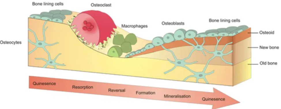
Furthermore, bone has been regarded as a “smart material” due to its self-repair ability when the damage is small.14 The self-repair ability is realized by a process known as bone
remodeling, during which older or damaged bone is gradually replaced by new bone cells.3
3
bone remodeling follows “Wolff’s Law”, which states that bone will accommodate itself to become denser/looser to the change of external load.16 In summary, considering the complexity
of natural bone, it is a grand challenge to find a treatment for large bone defects, which could structurally, mechanically and functionally replicate our natural bone.
Figure 1.2. Bone remodeling process for bone self-repair. (Reprinted from
https://www.york.ac.uk/res/bonefromblood/background/boneremodelling.html. Copyright by Biomedical Tissue Research, University of York. Reprinted with permission)
1.3 Current Treatments and Emerging Bone Tissue Engineering Field
To date, the majority of treatments for large bone defects have focused on developing bone graft to fill bone defects and stimulating new bone formation. Despite the fact that various bone grafts have been developed, they all have significant drawbacks. Autograft, which involves the use of host bone (usually from the pelvis iliac crest of the patient) to fill bone defect, has been regarded as the gold standard for bone grafts.17 However, its clinical application has been
greatly impeded due to the limited supply and risk of donor site morbidity.18 To mitigate this
issue, allograft19 and xenograft,20 which replace patients own bone tissue with bone tissue from
4
Considering the pitfalls in using natural bone grafts (i.e. autograft, allograft and xenograft) discussed above, synthetic biomaterials with good biocompatibility and mechanical properties have been extensively investigated as an alternative bone substitutes for treatment. These synthetic alternatives have demonstrated several advantages over natural bone grafts, such as availability, reduced infection, and mitigated host rejection.25 Initial attempts were focused on
the utilization of inert, nonporous materials with physical properties (such as mechanical strength) similar to natural bone to permanently undertake the function of damaged bone. Implants including metals (such as stainless steel, titanium, and alloys),26 ceramics (such as
alumina-oxide),27 and polymers (such as polymethylmethacrylate)28 have become the well-established
bone grafts for decades.29 However, the inert property of such materials will cause a non-specific
immune response from our body, which results in the formation of a soft fibrous tissue at the biomaterial-tissue interface.30 This indirect contact between the implant and the bone would
likely induce mechanical instability and dislocation over time. To overcome this problem, materials with bioactive surfaces were developed to promote bone formation at the material-bone interface, thereby inducing a stronger bonding between the bone and the implant. This bioactive surface can be easily obtained through coating material with bioactive ceramics such as HAp, bioactive glass, and β-tricalcium phosphate.31 While there has been significant progress in
developing synthetic bone grafts, there are still challenges to be addressed. For example, the mismatch of mechanical strength between synthetic bone grafts and natural bone often results in stress-shielding to surrounding bone32 and fatigue failure of the implant under cyclic loading.33
5
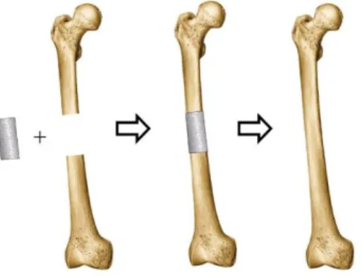
microenvironment for cell transplantation and proliferation. As the new bone starts to regenerate, the 3D scaffold will gradually degrade in vivo. Eventually, the synthetic scaffold will be totally replaced by the newly regenerated bone (Figure 1.3).34 It is envisioned that BTE will avoid the
disadvantages of current treatments and be the ideal treatment for bone defects in the near future.
Figure 1.3. Bone tissue engineering concept. (Reprinted from https://goo.gl/images/CtzKJF.
Reprinted with permission)
1.4 Bone Tissue Engineering: General Principles and Challenges
As shown in Figure 1.4, BTE relies on three main components: (1) a temporary 3D
porous scaffold made from natural and/or synthetic degradable biomaterials to provide
mechanical support and proper environment for bone regeneration; (2) biochemical factors such
as signals and growth factors to induce cells to the implant site and promote cells to regenerate
new bone tissue; and (3) cells (usually stem cells) to produce bone matrix.35 Typically, the BTE
surgical procedure starts with obtaining cells from patients, followed by seeds cells to scaffold to
allow the production of extracellular matrix (ECM) inside the scaffold in vitro, and finally
implants the scaffold with ECM at bone defect site in patients.36 After years of efforts, it was
6
Figure 1.4. The paradigm of bone tissue engineering. (Reprinted from reference 27 with permission. Copyright Royal Society of Chemistry)
Cells: Until now, multiple cell sources have been explored for BTE application. To name
a few, bone marrow aspirates,37 bone marrow mesenchymal stem cells,38 embryonic stem cells,
etc.39 Among these, mesenchymal stem cells (MSCs) obtained from bone marrow have been
widely studied due to their capability to differentiate into various tissues, including bone. Moreover, from a technical perspective, it’s relatively easy to collect MSCs from bone marrow. Preliminary clinical trials have indicated that implanted scaffolds seeded with MSCs promote faster bone tissue regeneration compared to scaffolds without cells.40 Nevertheless, in many
cases, the number of collected stem cells is not sufficient for clinical application. As a result, the biggest challenge is to increase the number of MSCs. In practice, we can expand the MSCs by cell culture in vitro, however, this process not only increases the surgery time and cost but also demonstrates complexity. For instance, it has been observed that stem cells will gradually lose their proliferation and differentiation ability during expanding (i.e., increase the number of MSCs) invitro.41,42
3D porous scaffold: The scaffold has been regarded as a crucial component for BTE
7
process. There are several key considerations in designing a scaffold, including biocompatibility,
biodegradability, proper mechanical properties, scaffold architecture, fabrication technique,
among others.43 A detailed review of scaffold design rules is provided in the following section.
Biochemical factors: Proteins that play a key role in cell proliferation and differentiation
are called biochemical factors.44 Recently, various studies have been focused on exploring
bone-related growth factors and applied them to BTE. It’s generally agreed that growth factors would
stimulate cell growth in bone scaffold.2 For instance, bone morphogenetic protein (BMP)45 (a
type of growth factor) alone (i.e. without scaffold and cells) can induce bone regeneration, which
indicates their impressive capability in promoting cell growth. However, the biggest challenge in
utilizing growth factors is targeted delivery to the repair site. Currently, various carriers for
growth factors have been examined, such as hydrogels and stimuli-responsive polymers.46
Unfortunately, they could not afford a steady, controllable and sustained release profile.42 Another significant challenge is the identification of the effective dose of growth factors for bone regeneration, preferably with minimal/tolerable side effects, which needs further study.47
1.5 Bone Scaffold Design Rules
Based on the discussions above, an ideal scaffold is essential for successful BTE applications. In principle, the scaffold should allow and/or promote cell attachment, proliferation, and differentiation, and most importantly, provide sufficient strength for load bearing. As a result, an ideal scaffold should satisfy following requirements: biocompatibility, good mechanical properties, proper pore size, bioresorbability, growth factor delivery, and easy fabrication.
8
body.48 More recently, “osteoinductive biomaterials” have been demonstrated to have great
promise for BTE due to their ability to stimulate MSCs to develop into preosteoblasts, which will promote bone regeneration.49
Good mechanical properties: Ideally, the scaffold should have mechanical strength comparable to natural bone in the implanted site, which helps load transfer during bone regeneration process.50,51
Proper pore size: The scaffold should possess a minimal pore size of 50 μm for effective cell seeding. Larger pores are preferred as they provide better cell seeding and essential nutrients exchange for cell survival. Recently, research has suggested that the scaffold should have inter-connected pore structure with pore size ranging from 200-350 μm.52 Moreover, it was
demonstrated that the combination of micro and macro pores would enhances bone regeneration.53 It should be mentioned that the scaffold porosity is also closely related to its
mechanical strength and is largely determined by the fabrication technique.54 As a consequence,
designing the porosity of scaffold should also consider the balance of these factors.
Bioresorbability: An ideal scaffold should be able to degrade with time in vivo, preferably at a controlled resorption rate, produce non-toxic degradation products and create space for the new bone gradually. The degradation behavior of scaffold should vary based on the targeted application.55
Growth factor delivery: As discussed in section 1.4, the effective incorporation of growth factor can promote cell growth and enhance bone regeneration.
9
and porosity, which influence bone regeneration.56 Recently, 3D-printing together with
computational topology design (CTD) has been demonstrated as a powerful way to fabricate scaffold with controlled pore size and porosity.57
1.6 Current Materials Options and Limitations
Until now, various materials have been explored as BTE scaffolds. As shown in Table
1.1, these systems include biodegradable polymers, ceramics, and composites.58,59 Generally,
these material systems have acceptable biocompatibility and produce nontoxic degradation
products; however, none of them can meet the entire set of criterion discussed in Section 1.5.
There are limitations with each material system, as discussed below.
Biodegradable polymers: Various polymers - either from natural origin (collagen (Col),
gelatin (Gel), alginate, chitin, etc.)60,61 or synthetic origin (polycaprolactone (PCL), polylactic
acids (PLA), poly(glycolic acid) (PGA), etc.)62 - have been explored for bone scaffold
application.63 The main drawbacks for these polymers are their low mechanical strength (i.e. they
cannot sustain stress loading in the implanted site over a long period of time) and poor
formability. Moreover, the degradation rate of these polymers is too fast for bone regeneration
(i.e. materials erode in body fluid at a fast rate, leading to a quick loss of massive amount of
materials), which results in low bulk corrosion resistance.64 Thus, for synthetic polymers to be a
viable option for BTE, it needs to display a more controllable degradation rate, tunable
mechanical properties and can be prepared with easy fabrication techniques. Finally, it is also
desirable to design polymers that can improve cell attachment and demonstrate potential to
deliver growth factors.
Bioactive ceramics: These can be from either natural or synthetic in origin such as HAp,
10
ceramics and our natural bone, they have shown high compressive strength, providing high
resistance to deformation.65 Another advantage of ceramics is that they can be easily fabricated
into scaffold. Nevertheless, the utilization of ceramics is impeded by two reasons. First, they
only show relatively slow degradation, which is not favored for BTE. Second, ceramics are often
brittle, which would likely to cause fracture after implantation.
Composite: The composite systems, consisting of two or more materials, have emerged
with the hope to incorporate strength from each material to this complex system.58,59 In general,
there are three types of combinations, namely co-polymers, polymer-polymer blends, and
polymer-ceramic composites. For instance, poly(lactic-co-glycolic acid) (PLGA) is a copolymer
of polylactide and polyglycolide, which has been regarded as a promising option for BTE
application due to its biodegradability and ease of fabrication. Moreover, to address necrosis,
caused by the acidic degradation product of PLGA, polyphosphazenes have been blended with
PLGA to neutralize the acidic degradation product by releasing only neutral or basic products.66
Recently, polymer-ceramic composites combining the advantages of polymers and ceramics
have emerged as the most promising option for scaffold since they have shown tunable
mechanical strength, adjustable degradation rate and good biocompatibility. In fact, bone itself is
11
Table 1.1. Current material options and related properties
Polymers Bioceramics Composites
Compressive strength Poor
(2-40MPa)
Good (50-400MPa)
Fair (60-150 MPa)
Degradation Very Fast
(2-12 mo.)
Slow Tunable
Formability Poor Good Tunable
Examples Collagen (COL)
Gelatin (GEL)
Alginate, Chitin
PCL, PLA, PGA
Hydroxyapatite (HAp) Bioactive glass Tricalcium phosphate Calcium silicate HAp-Gel HAp-Col PLGA 1.7 Biomimetic Hydroxyapatite-Gelatin Composite Materials
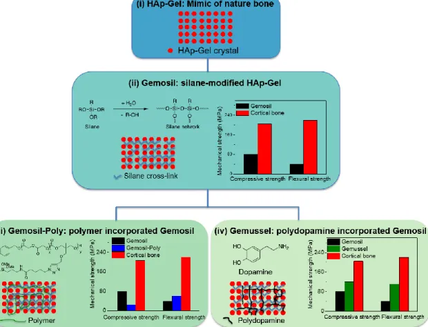
For all these reasons, the You group in Chemistry and the Ko group in the Dental School have formed a strong collaboration to explore and develop polymer-ceramic composite-based materials for bone scaffolds. Specifically, we focused on mimicking natural bone since natural bone is perfect. In this decade long collaboration, we have developed several generations of biomimetic composites as shown in Figure 1.5.
HAp-Gel: We first developed a nanocomposite named HAp-Gel, mimicking
hydroxyapatite-collagen (HAp-Col) in nature bone (i.e., gelatin (Gel) is denatured collagen (Col), mimicking the function of Col in nature bone). HAp-Gel was prepared by co-precipitation of calcium hydroxide (Ca(OH)2)with phosphoric acid in the presence of gelatin. Similar to the
interaction between various components in natural bone, HAp-Gel showed chemical bond formation between calcium cations of HAp nanocrystals and carboxyl anions of gelatin macromolecules. Furthermore, HAp-Gel has a self-organized structure along c-axis of crystalline of HAp nanocrystals, which would account for the improved mechanical strength of this composite.68 However, HAp-Gel is a particulate powder and hard to form the
scaffold.
(bis[3-12
(trimethoxysilyl) propyl] ethylenediamine (enTMOS)) as the chemical linker to facilitate the binding and solidification of HAp-Gel, and named the composite Gemosil (i.e., silane-modified HAp-Gel composite).69 Compared to previously developed glutaraldehyde linker treated
HAp-Gel,70 this new composite, Gemosil, demonstrated increased compressive strength and good cell
compatibility. Still, the compressive strength of Gemosil was only ~40% of the value achieved by cortical bone (80 MPa vs 205 MPa11). The biaxial flexural strength of Gemosil was merely
~18% of that achieved by the cortical bone (40 MPa vs 220 MPa71).
Gemosil-Poly: To further improve the mechanical strength of Gemosil, we have attempted to incorporate biocompatible polymers. For example, we designed a silane-functionalized poly(L-lactide-co-propargyl carbonate) (P(LLA-co-PC)) copolymer, which was blended into the Gemosil composite, aiming to enhance the long-range interactions among different components within the Gemosil composite. We named this new composite as Gemosil-Poly.72 However, this polymer-enriched composite only improved the biaxial flexural strength
from 40 MPa to 60 MPa, still much lower than that of the natural bone. This limited improvement was attributed to the poor solubility of polymer in the processing solvent MeOH, resulting in an inhomogeneous mixing of polymer with other components in the system and weak adhesion among different components.
Gemussel: Most recently, we introduced polydopamine (PDA) – a mussel adhesive protein inspired material that has shown excellent coating and adhesion properties – into Gemosil, aiming to improve the adhesion between the hydrophilic HAp-Gel and the hydrophobic siloxane matrix and named this latest generation of composite as Gemussel. However, the compressive strength improvement was still limited, only from 80 MPa to 120 MPa.73 This
13 interaction of collagen in natural bone.
Thus, the aim of this dissertation is to further improve properties of HAp-Gel-based composite to make it a better material for scaffold for BTE application.
14
Chapter 2 DRAMATIC IMPROVEMENT OF MECHANICAL STRENGTH OF SILANE-MODIFIED HYDROXYAPATITE-GELATIN COMPOSITES VIA
PROCESSING WITH CO-SOLVENT
2.1 Introduction
While substantial improvements have been made in improving the mechanical strength of HAp-Gel based composites, the resulting composites still do not meet the requirements for BTE application. The limited improvement of composite mechanical strength with biocompatible polymer or polydopamine (PDA) made us speculate that the main reason for the poor mechanical strength of Gemosil (i.e. silane-modified HAp-Gel) might be the intrinsically weak silane network in this composite. Given that silane matrix is the major component of Gemosil composite (~ 46% by weight), engineering the silane network to dramatically improve its mechanical strength would be an alternative– perhaps an ideal – solution. 1
It has been well established that the silane network formation is a sol-gel process. This process starts with hydrolysis of alkoxide silane precursors to form silanol, followed by the condensation/polymerization between the silanol groups to form siloxane (Si-O-Si) linkages.74
The gel structure (e.g., morphology and porosity), which decides the mechanical strength of as formed sliane network, can be significantly influenced by the processing method and specific conditions, including pH, R ratio (R=[H2O]/alkoxide precursor),75 solvents76,77 and dry process.74
As a result, to produce a gel with desirable properties, the processing method and conditions need to be carefully optimized. Processing conditions become even more important when
15
preparing composite materials that contain the silane network. For instance, an inhomogeneous mixing of different components in the composite can induce fractures during drying,74 which can
significantly decrease the final mechanical strength of such composites.
Among the aforementioned factors that could influence the gel structure, controlling the drying process of the sol to gel formation has been shown to have a crucial impact on the mechanical property of the final composite.74 To improve the ease of drying while minimizing
cracking, co-solvents78,79 have often been employed. Moreover, different co-solvents exert
different control on the kinetics of hydrolysis and condensation, resulting in the formation of sliane network with different structures (Scheme 2.1) and different physical properties.76,77 All
16
Scheme 2.1. enTMOS network formed in different solvent system
2.2 Co-Solvent Effect: Observation
According to previous findings, on the one hand, low viscosity solvents promote rapid hydrolysis, which would likely resulted in condensed network caused by fast condensation reactions to occur (due to the increased concentration of reactants for condensation).76 On the
other hand, non-polar aprotic solvent is preferred for a fast condensation reaction. This is because hydrogen bonding and/or electrostatic interactions between polar solvents and the nucleophilic substitution reaction intermediate will slow the rate of condensation.77 To form a
17
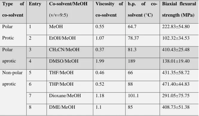
Table 2.1. Biaxial flexural strength of composite with different co-solvents
Type of
co-solvent
Entry Co-solvent/MeOH
(v/v=9:5)
Viscosity of
co-solvent
b.p. of
co-solvent (°C)
Biaxial flexural
strength (MPa)
Polar Protic
1 MeOH 0.55 64.7 222.83±54.80
2 EtOH/MeOH 1.07 78.37 102.32±34.53
Polar aprotic
3 CH3CN/MeOH 0.37 81.3 410.43±25.48
4 DMSO/MeOH 1.99 189 138.01±19.40
Non-polar aprotic
5 THF/MeOH 0.46 66 431.35±58.72
6 THP/MeOH 0.52 88 471.40±44.83
7 Dioxane/MeOH 1.18 101.1 291.05±75.75
8 DME/MeOH 1.1 85 408.73±51.38
Our results in Table 2.1 clearly demonstrate that the co-solvents indeed have a strong influence on the biaxial flexural strength of the composite. First, as we expected, among the three types of co-solvents we studied, aprotic ones – with the exception of dimethyl sulfoxide (DMSO) – improve the mechanical strength of the composite more than protic ones. In some cases, we could even increase the mechanical strength over 100% when compared with that of the original Gemosil (prepared with MeOH only, entry 1 of Table 2.1). For instance, when using acetonitrile (CH3CN) and tetrahydrofuran (THF) as
the co-solvents, the flexural strength of such composites increases from 222 MPa to around 410 MPa and 431 MPa, respectively (entry 3 and entry 5 in Table 2.1). This can be explained by the fact that THF and CH3CN are aprotic in nature, which can promote
fast condensation reaction when compared with the protic ones (such as methanol (MeOH) and ethanol (EtOH)). Moreover, THF and CH3CN also have relative lower viscosity
18
reasons, the addition of THF or CH3CN would result in a dense silane network as shown
in Scheme 2.1 with higher flexural strength. This can be further supported by the impressive improvement of compressive strength, which increases from 97 MPa when processed with pure MeOH to 195 MPa when adding THF as the co-solvents (Table A2.1, entry 2 and 4, Appendix). However, if all MeOH was replaced by THF (i.e., THF only) or CH3CN (i.e., CH3CN only), the sol-gel reaction would be completed too fast (gelation
19
CH3CN/MeOH, THF/MeOH, and DME/MeOH. A range of viscosity values (0.37, 0.52
and 1.1) were observed, yet all co-solvents offered similarly high flexural strength of the final composites (over 400 MPa).
2.3 Hypothesis for Co-solvent Effect
We hypothesize that the effect of co-solvent on the mechanical strength of the Gemosil composite is mainly due to the combined effects from hydrolysis and condensation of silanes that changed the morphology of the composite, rather than from co-solvent induced chemical reaction/interaction between different components within the composite. Specifically, adding co-solvent into the processing co-solvent (i.e., MeOH) can have two functions during the composite formation. First, mixing different co-solvents with MeOH increases the total volume of solvent when compared with the original processing method reported previously. The extra solvent would allow the various components, including HAp-Gel, Ca(OH)2 and enTMOS, to mix more
20 2.4 FT-IR Study
To experimentally verify the hypothesis, we first applied FT-IR spectroscopy to identify specific chemical bonds in the final gel structure and to monitor the sol-gel reaction process.80
We started with pure enTMOS gels formed from different co-solvents/MeOH systems to probe whether the co-solvent reacted with enTMOS. Three representative co-solvents/MeOH systems from these three different types (Table 2.1) were selected, THF/MeOH, CH3CN/MeOH and
MeOH only. First, the FT-IR of pure enTMOS network prepared with CH3CN/MeOH and
THF/MeOH show characteristic peaks for enTMOS gels (e.g., Si-O-Si stretching at 1029 cm-1
and 1118 cm-1), indicating the formation of aminosilica matrix. As expected, enTMOS gels made
from different co-solvent/MeOH systems demonstrated almost identical absorption spectra (from 4000 cm-1 – 400 cm-1) to that of the enTMOS gel made from MeOH only (Figure 2.1 (a)). This
indicates that the co-solvents did not react with the enTMOS during the sol-gel process. Moreover, the almost identical absorbance of peaks corresponding to the Si-O-Si bond for enTMOS processed with different solvents indicates that the total amount of Si-O-Si bond is comparable across the samples. We also performed 29Si solid state NMR to further investigate
the variety of Si bonds (e.g., Si-O-Si and Si-OH) that were involved in the sol-gel process. As shown in Figure A2.2 in Appendix, for all silane networks with different processing co-solvents, we observed two Si peaks. The signal at – 65 ppm is corresponding to the formation of Si-O-Si, whereas the other signal at – 58 ppm is attributed to the Si-OH structure from the incomplete condensation.81 Again, the 29Si NMR spectra are very similar across the samples, implying
similar amount of Si species. Second, in order to examine whether the co-solvents would react with other components in the Gemosil composite, i.e., HAp-Gel and Ca(OH)2 with
21
spectra of composites made from different co-solvents/MeOH systems are almost identical to each other (Figure 2.1 (b)), indicating that the co-solvents didn’t react with the remaining components (i.e., HAp-Gel and Ca(OH)2 with CHX) in the Gemosil system. Most importantly,
we did not observe any co-solvents/MeOH characteristic absorption in all FT-IR spectra, indicating that solvent was completely removed after drying. This is ideal for BTE application since the residual co-solvent (if any) could be toxic.
Figure 2.1. FT-IR spectra of (a) enTMOS gels and (b) Gemosil composites prepared from
different solvent systems. 2.5 Morphology Study
Results from the FT-IR study rule out the possibility that the improvement of mechanical strength of these co-solvent-treated composites was from co-solvent-induced chemical interactions/reactions. Thus, it is very likely that the optimized morphology of the Gemosil composite is the main reason for the improved flexural strength. We next used SEM to investigate the morphology (i.e., phase distribution, porosity) of the composite formed from different co-solvent/MeOH systems and of the pure enTMOS network. We chose to study the cross-section of the composite made from two representative co-solvent/MeOH systems, namely, CH3CN/MeOH and THF/MeOH. Composites made from only MeOH or THF were also
4000 3000 2000 1000 0.8 1.0 (b) Trans mi tance (% ) Wavenumber (1/cm) MeOH composite THF/MeOH composite CH
3CN/MeOH composite
22
investigated as the reference. From the cross-section images of these composites (Figure 2.2), one can clearly observe that composite formed from CH3CN/MeOH or THF/MeOH has a much
smoother surface (less visual cracks), which agrees well with the greatly improved flexural strength of the composites (Table 2.1). In contrast, composite made from MeOH only has large cracks (Figure 2.2(a)). Furthermore, there are two distinct phases probed by EDS: one is enriched with HAp-Gel, while the other is enriched with silsesquioxane phase (Figure A2.3 in Appendix). Comparing the phase distribution in composites made from MeOH only or THF only with that in composites made from CH3CN/MeOH or THF/MeOH, the enTMOS phase and
HAp-Geldistribute more homogenously with the addition of co-solvent (CH3CN or THF). We
attribute this homogenous phase distribution to the increased total volume of solvent with the addition of co-solvent, which would help the homogenous mixing of different components.
More importantly, these co-solvents can control the drying process of forming the Gemosil composite, since the mixed solvent (co-solvent+MeOH) would have a slower evaporation rate than that of the pure MeOH. If this were the case, a further deviation of the boiling point of co-solvent from that of the main solvent (i.e., MeOH) would have a more appreciable effect on the drying process and the morphology of as-formed composite. Indeed, the composite made from dioxane/MeOH (Figure A2.4 (c) in Appendix) shows larger cracks than the one made from THF/MeOH. This can be ascribed to the fact that the boiling point of dioxane (101 °C) is too far from that of MeOH than that of THF (66 °C).
23
composite made with THF only shows less homogeneity and weaker mechanical strength (Figure 2.2 (d) and entry 5 in Table A2.1 in Appendix). We speculate that a too fast gelation would occur when pure THF was used, which would lead to the inhomogeneous mixing of different components in the composite.
Finally, we applied TEM to investigate more details about each component in the composite. In principle, if the co-solvents did not react with the HAp-Gel crystal, we should be able to observe intact HAp-Gel crystals. Indeed, TEM images of composites show the Hap-gel nanocrystals remain intact after the processing with co-solvents (Fig A2.6 in Appendix). This further proves that the improvement of mechanical strength by these co-solvents could be solely related to the optimized enTMOS matrix structure and the more homogenous mixing of different components in the composite.
Figure 2.2. SEM images of composites made from (a) MeOH only; (b) CH3CN/MeOH; (c)
24 2.6 Biocompatibility Study
Good biocompatibility of the composite is a prerequisite for BTE. Previous study has demonstrated that Gemosil has good biocompatibility.69 In the current study, we add
co-solvent and CHX as additional components during the processing, and there is a possibility that the residual co-solvent and CHX could lead to cell toxicity. To investigate this possible pitfall, the following experiments were carried out. We chose THF/MeOH as the representative co-solvent/MeOH system and varied the amount of co-solvent and CHX as independent variables. Experimentally, four different types of composites made from (a) MeOH, Ca(OH)2, (b) MeOH, Ca(OH)2 CHX, (c) THF/MeOH, Ca(OH)2, (d)
THF/MeOH, Ca(OH)2 CHX were incubated with cells. The viability of the potential
transplanted cells in BTE application, rMSCs, was monitored by RealTime-GloTM MT
cell viability assay. We used this method to distinguish the direct toxicity monitored by the cells attached to the composites and the leaching toxicity measured by the cells in the well surrounding the bulk materials. However, a quick screening showed poor cells attachment on bulk composite made from Ca(OH)2 with CHX and its surrounding area in
25
with just Ca(OH)2, the compressive strength of composites (with or without CHX) was
comparable (Table A2.2 in Appendix). Therefore, we recommend to replace Ca(OH)2
CHX with Ca(OH)2 for future use of the composites where good biocompatibility is
required.
Figure 2.3. Cell viability test by RealTime-GloTM MT cell viability assay (two way ANOVA analysis, P=0.0012).
2.7 3D Porous Scaffold Fabrication and Mechanical Properties
26
Furthermore, the achieved compressive strength of scaffold processed with co-solvent is comparable to that (1-13 MPa) of the cancellous bone.13 All these indicate a great
potential of such scaffold for BTE. Further in vivo test is in progress to access the feasibility of such scaffolds for biomedical applications.
Figure 2.4. (a) Picture of the porous scaffold (pore size: 400 μm, porosity: 50%) and (b) compressive strength of porous scaffold processed with different co-solvents (student t-test,
P=0.0001). 2.8 Conclusion
In conclusion, we successfully improved the mechanical strength of our previously developed Gemosil composite significantly with the aid of selected co-solvents (e.g., THF, CH3CN, THP, etc.). We further demonstrated that the improvement of mechanical
27
biocompatibility of this new Gemosil composite. Finally, we demonstrated that porous scaffold processed with co-solvent can be easily made yet maintained good compressive strength. All these results point to that this newly modified Gemosil composite is a very promising candidate for BTE. Currently, we are focus on evaluating the effect of this new scaffold for bone regeneration in vivo.
2.9 Experimental Section Materials
HAp-Gel and Ca(OH)2 powder was prepared by the method reported previously.68
Ca(OH)2 with CHX was prepared by doping 5%-10% CHX into Ca(OH)2 powder. 95%
bis[3-(trimethoxysilyl)-propyl]ethylenediamine (enTMOS) and 62% enTMOS in MeOH were purchased from Gelest, Inc. (Morrisville, PA, USA). Solvents, including MeOH, EtOH, CH3CN, THF, tetrahydropyran (THP), DMSO, dimethoxyethane (DME),
1,4-dioxane were purchased from Alfa Aesar and used as received. Ammonium persulfate (APS) was purchased from Sigma-Aldrich and used as received.
Preparing the composite
The method for making the composites was adapted from previous report.73 300
mg HAp-Gel, 200 mg of Ca(OH)2 with CHX powder were transferred into a mortar and
28
mold (size: diameter: 15.58 mm and thickness: 2.8 mm, designed for 3-point bending test), which lay on a smooth glass slide. Another smooth glass slide was carefully covered at the top of the mold to remove extra material. This “sandwich” structure (glass slides at the top and the bottom, material in the disk mold in between) was clamped and sealed into a plastic bag for one week to let the composite dry slowly. Finally, the sample was further dried in an oven at 54 °C for 5 days before the flexural strength test. The reason why the temperature was set at 54 °C is because gelatin has been shown to degrade gradually around 100°C and collagen has been shown to denature to gelatin between 60 °C and 80°C. Thus, we chose 54 °C to remove the remaining solvent as well as to avoid the degradation of gelatin or collagen. For comparison, composites without co-solvents, namely all MeOH, were also prepared according to the same procedure described above. Furthermore, previously reported Gemosil composite69 made from 62% enTMOS was also repeated here as a
reference. Additionally, cylinder-shaped samples with a 1:2 ratio of diameter (3.8 mm) to length (7.6 mm) were made according to our previous report73 with the same composition
described above. To prepare pure enTMOS network without HAp-Gel and Ca(OH)2
CHX, APS was directly added to the pre-mixed enTMOS solution. After gelation, same drying process was applied as described above.
Compressive and biaxial flexural test
The testing procedures were performed according to methods established in our previous publication.72 Cylinder-shaped samples (3.8 mm diameter by 7.6 mm length) or
29
of 0.5 mm/min. Same calculation method72 was used to get compressive strength and
biaxial flexural strength. A minimum of three samples for each group were used in all mechanical testing.
FT-IR
Bulk composites were ground into fine powder. Then the fine powder was spread directly on diamond crystal and analyzed by Fourier-transform Infrared spectroscopy (FT-IR) using attenuated total reflection (ATR) mode.
29Si solid state NMR
29Si CPMAS NMR spectra were acquired on a Bruker DMX 360MHz WB NMR
spectrometer operating at 71.55 MHz for 29Si and 360.13 MHz for 1H. A Q8M8 (i.e.
octakis(trimethylsiloxy)silsequioxane) sample was used to calibrate the proton pulse width and the silicon power level for the contact pulse (10ms). A relaxation delay of 5 s and a sweep width of 27 kHz was used. Total number of scans ranged from 4k to 16k. Spectra were processed with 50Hz line broadening and referenced to an external TMS sample.
Morphology study
30
this solution was added to the TEM grid for imaging using a JEOL 2010F-FasTEM (JEOL USA, Inc.).
3D porous scaffold fabrication
A 3D cylindrical porous template (diameter: 5 mm and height: 10mm, pore size: 400 μm, porosity: 50%) was designed using SolidWorks software (Dassault Systems SolidWorks Corp.,Waltham, MA, USA). This template (stl format) was then used to print a 3D wax mold made of Solidcape® Model (Solidscape Inc., Merrimack, NH, USA) with 0.16 mm2 trusses and 0.16 mm2 pore sizes (continuous space) using a Solidscape 3D
printer (Solidscape Inc., Merrimack, NH, USA). Next, the composite mixture was prepared on the cold stage as described above and injected to the 3D-printed mold before the materials was let to solidify. After setting for 3-5 minutes, the wax mold and the composite was immersed in acetone for 15 minutes to remove the wax template and release the 3D porous composite based scaffold, which is shown in Figure 2.4(a). The porous scaffold was air dried for one week, followed by drying at 52 °C for 4 days prior to the compression test. Same method and data analysis were used here to obtain the compressive strength. The compressive strength of the porous scaffold was averaged from at least three samples.
Bulk material biocompatibility study via RealTime-GloTM MT cell viability assay
Bulk disk samples (diameter: 6 mm, thickness: 1 mm) made from THF/MeOH or MeOH were leaching in H2O for 3 days, followed by gas sterilization and balanced in the cell growth
31
32
Chapter 3 CATECHOL-FUNCTIONALIZED ADHESIVE POLYMER FOR ENHANCING MECHANICAL STRENGTH OF SILANE-MODIFIED HYDROXYAPATITE-GELATIN COMPOSITE IN WET CONDITION
3.1 Introduction
In Chapter 2, we optimized the silane (i.e., enTMOS) sol-gel reaction condition through applying selective co-solvent during processing and were able to dramatically improve the mechanical strength of Gemosil composite (i.e., silane-modified HAp-Gel composite). For instance, the new Gemosil composite processed with THF as co-solvent, demonstrated almost twice the compressive strength (195 MPa vs. 97 MPa) and biaxial flexural strength (431 MPa vs. 222 MPa) of the original Gemosil composite without THF, respectively. These findings offer valuable guidelines when selecting co-solvents to improve silane sol-gel processing and the mechanical strength of such composites. Moreover, the co-solvents can be completely removed during drying, thereby not compromising the biocompatibility of composite. Finally, we have shown that porous scaffolds could be easily fabricated, and such porous scaffolds demonstrated values of compressive strength around 11 MPa, comparable to those of cancellous bones.13
However, there are challenges in using such porous scaffolds for bone regeneration in vivo. Our preliminary in-vitro degradation study showed that the scaffold degraded rapidly when immersed in water (H2O). Compressive strength of the porous scaffold decreased from 11 MPa to 0.5 MPa
after it was immersed in H2O for 3 days. Therefore, our next goal was set to develop a more
33
One possible option is to incorporate a water-insoluble, biocompatible and cross-linkable polymer with sufficient mechanical strength into the composite, assuming the strength of such polymer networks was able to be carried into the composite. There have been numerous reports on blending polymers with various inorganic materials to improve the performance of the final composites, for instance, tuning their degradation profiles and increasing the toughness.54,82,83
Given that biocompatibility and biodegradability are required for our application, we turned our attention to synthetic polymers with these features, such as poly (L-lactide acid)(PLLA),84,85
poly(lactic-co-glycolic acid)(PLGA),86,87 polycaprolactone(PCL)88, and poly(trimethylene
carbonate)(PTMC).89,90 These polymers have been long established as blends for a variety of
medical applications due to their unique mechanical and degradation properties. Previously, our group designed a silane-functionalized P(LLA-co-PC) copolymer, aiming to enhance the long-range interactions among different components in Gemosil by incorporating this copolymer within the Gemosil composite.72 In that study,72 this copolymer demonstrated several advantages.
First, copolymerization of PLLA with PC lowered the glass transition temperature (Tg) of pure
PLLA,91 which would help to ‘soften’ PLLA and provide better toughing effect to mitigate the
brittle nature of the Gemosil composites.92 Second, the PC monomer allowed the incorporation
of a pendant alkyne group for further post-functionalization. In the previous study, we functionalized the P(LLA-co-PC) copolymer with silane side groups on the PC unit; such silane-functionalized P(LLA-co-PC) copolymers were designed to react with the enTMOS silane cross-linker in the Gemosil composite during the sol-gel process, which would incorporate these copolymers into the Gemosil composite to further reinforce the composite.72 Indeed, we
34
strength of the polymer-incorporated composite greatly decreased (from 80 MPa to 30 MPa), likely due to the poor adhesion between the hydrophilic HAp-Gel and the hydrophobic polymers.
To increase the adhesion between the aforementioned components, we decided to seek inspiration by searching nature’s methods of adhering biomaterials under aqueous conditions. A great example is mussels, which have demonstrated impressive adhesion to various substrates under wet conditions. These impressive adhesion properties are due to mussel adhesive proteins, which have several key structural features.93 For example, mussel adhesive proteins’ sequences
have two main types of constituents, namely, catecholic amino acid (e.g., L-3,4-dihydroxyphenylalanine (L-DOPA)), and amine-containing amino acids (e.g., lysine, histidine and arginine).93 Further studies revealed that the catechol groups in L-DOPA were able to form:
a) adhesive interactions at the substrate surface through hydrogen bonding, π- π electron interaction and cation- π interaction,94,95 and b) a cross-linked network to improve cohesive
strength through metal chelating95,96 or oxidative aryl-aryl coupling.97,98 All these contributed to
mussel’s impressive adhesive properties. Moreover, amine group could provide a synergistic effect to mussel’s adhesion through ionic bonding to negatively charged surfaces 99 and
intermolecular cross-linking with o-quinones through Michael addition or Schiff-base formation.95 Inspired by these findings, various synthetic polymers with catechol alone,97 or
coupled together with amine 100 have been investigated to develop functional polymers with
strong adhesive properties under wet condition.101 Among these, dopamine, perhaps the simplest
molecule that covalently linking catechol and amine, has shown impressive adhesive and coating properties with its polymers.102 Recently, we introduced polydopamine (PDA) into our Gemosil
35
strength, from 80 MPa to 100 MPa.73 This might be caused by the low molecular weight of
PDA,103 which would not reproduce the long-range interaction of collagen in nature bones.
36
Scheme 3.1. Proposed polymer network formed through the catechol oxidative coupling between
polymer and dopamine
As shown in Scheme 3.1, we first synthesized P(LLA-co-PC) with pendant acetylene groups, following our previous report.72 A post-functionalization of the P(LLA-co-PC) with
37
of scaffold could be improved by 20% under wet condition with the addition of the copolymer of and dopamine.
3.2 Synthesis of Monomer and Cross-linker
The synthesis of PC monomer, as shown in Scheme 3.2, was adapted from our previous report,72 and the targeted cross-linker molecule, 4-(4-mercaptobutyl) benzene-1,2-diol (i.e.,
Catechol-4C-SH), was prepared according to Scheme 3.3. Specifically, a Friedel-Crafts acylation of the commercially available 3,4-dimethoxybenzene, followed by a NaBH4 reduction,
readily afforded the key intermediate (3.2’).104 This intermediate then went through a
nucleophilic substitution of the bromide with the thioacetate to accomplish compound (3.3’). Treating compound (3.3’) with the strong Lewis acid BBr3 smoothly removed the methyl
protecting groups, revealing the catechol group, which was then followed by the removal of acetate group to reveal the thiol group under acidic condition and afforded the target molecule (3.4’). The chemical structure of the product formed after each step was confirmed by 1H NMR (Appendix for Chapter 3).
38
Scheme 3.3. Synthesis route of Catechol-4C-SH
3.3 Synthesis of P(LLA-co-PC) Copolymers and Post-functionalization with Catechol The PLLA-co-PC copolymer was prepared according to our previous report.72 The
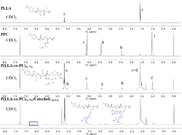
successful synthesis of copolymer was characterized by 1H NMR spectra (Figure 3.1 and
Appendix for Chapter 3). As demonstrated in our previous report,72 copolymers with different
amount of PC in the backbone, as shown in Table 3.1, could be readily obtained by varying the loading mol% of PC (0-50 mol%). We also observed that the number average molecular weight (Mn) of copolymer, characterized by gel permeation chromatography (GPC), gradually decreased
with the increasing amount of loaded PC monomer (Figure A3.1 in Appendix). This was attributed to a faster consumption rate of LLA compared to PC during the copolymerization.72
Table 3.1. Summarized polymerization data for P(LLA-co-PC) copolymers Entry PC loading
(mol%)
PC incorporation
(mol%)
Mn
(kg/mol)
Mw
(kg/mol)
Dispersity (Đ)
1 16.7 11.7 16.4 22.4 1.36
2 20 19.5 12.6 17.1 1.35
3 30 24.0 9.3 12.7 1.36
4 50 48.3 6.1 8.6 1.41
39
Scheme 3.4. Synthesis of PLLA-co-PC copolymer functionalized with catechol through “thiol-yne” click chemistry
Having successfully obtained the P(LLA-co-PC) copolymer, we next attempted to functionalize the pendant acetylene of PC with catechol through “thiol-yne” click chemistry as shown in Scheme 3.4. “Thiol-yne” click chemistry 105 has been demonstrated as a powerful
method for post-functionalization of polymers. Mechanistically, each yne moiety first reacts with one thiol functionality to form a vinyl sulfide (i.e., monoaddition product), followed by subsequent reaction of the vinyl sulfide with the second thiol to yield the 1,2-disubstitued adduct (i.e., bisaddition product).106 Interesting, according to previous report,107 for
post-functionalization of polymers with the “thiol-yne” method, one would need to have thiols in a large stoichiometric excess (usually 10 ×) to obtain close to 100% bisaddition product. In our case, we found under the stoichiometric (2 thiols:1 yne) condition, successful post-functionalization of the copolymer with catechol were achieved, evidenced by the disappearance of pendant acetylene protons at δ=2.45 ppm and appearance of the phenyl protons at δ=6.56 ppm (associated with the phenyl ring of Catechol-4C-SH) in 1H NMR spectra (Figure 3.1).
40
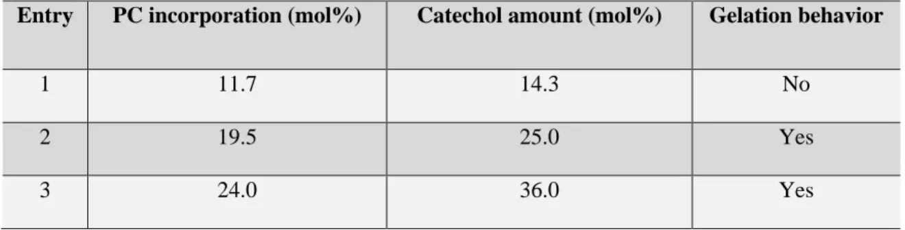
lactide methane protons (δ=5.18 ppm) in 1H NMR spectra, we were able to calculate the
incorporated catechol amount. We found that both monoaddition product and bisaddition product were obtained. For instance, when functionalizing P(LLA-co-PC)11.7% (i.e., entry 1 of Table 3.1,
11.7 mol% of PC in the polymer backbone) with catechol, we found that the ratio of incorporated catechol to lactide in the polymer is around 14.3% (i.e., in average 1 yne reacted with 1.22 thiols). Accordingly, we named the final copolymer as P(LLA-co-PC)11.7%(Catechol)14.3% for
clarity.
Figure 3.1. The 1H NMR spectra of homopolymers, copolymer and catechol functionalized
copolymer. 3.4 Optimization of Catechol Amount