Implementation and Bit Error Rate analysis of BPSK
Modulation and Demodulation Technique using
MATLAB
G.Tharakanatha1, SK. Mahaboob kamal basha2, Vijay Bhaskar chanda3, I.Hemalatha4
Dept. of ECE, Sir CRREDDY College of engineering, Eluru, A.P1, 2 Scientist ’D’, Research Center Imarat, DRDO, Hyderabad3
Associate Professor, Dept. of ECE, Sir CRREDDY College of engineering, Eluru, A.P4
Abstract
—
This paper presents the theoretical background of digital modulation and evaluate the performance of BPSK system with respect to Bit error Rate and finally implement Binary Phase shift Keying modulation technique in MATLAB. The main objective of any communication system is to receive the transmitted data accurately. There are lot digital modulation techniques that are well flourished in the communications field, selection of a suitable modulation technique for an application depends on many factors like Bit error rate, data rate, design complexity etc., one of the modulation techniques that is used in many areas of applications is the BPSK modulation. It is widely used due to its low BER and simplicity in design when compared to other modulation techniques.The BER for BPSK is performed using Matlab Graphical User Interface tool i.e., BERTool. The modulated signal is produced by modulating a carrier according to the binary code. The binary code taken here is the Gold code sequence. Such modulated signal is transmitted through AWGN channel. The resulting noisy modulated signal is demodulated using the BPSK demodulation technique.
The complete system simulations are carried out in MATLAB R2008a and the same will be verified using Matlab Simulink environment.
Keywords—AWGN, BER, BERTool BPSK, Gold
Code Sequence, GUI, Matlab, Simulink
I.INTRODUCTION
In the last few decades, a major transition from analog to digital communications has occurred and it can be seen in all areas of communications. One of the main reasons is that digital communication system is more reliable than an analog one.
The main objective of this paper is to give a brief introduction of the digital communications. Later on the BPSK system is simulated in Matlab text editor and it is implemented in Simulink.
II. THEORETICAL BACKGROUND The main factor that differentiates both the analog and digital communications is the modulation technique used with them. The modulation process converts a baseband signal into a band pass signal.
In analog communications an analog signal is taken
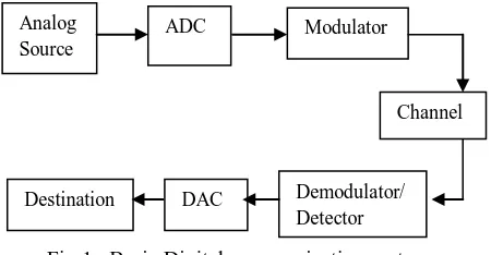
Fig 1: Basic Digital communication system
In the basic digital communication model as shown in Fig1 the first three blocks of the diagram (analog source , Analog to Digital Converter(ADC), and modulator) together comprise the transmitter .The source represents the message to be transmitted which includes speech, video, image, or text data tec.,. If the information has been acquired in analog form, it must be converted into digital form to make our communication easier. This analog to digital conversion is done by the ADC block. The modulator converts the digital signal into band pass signal and is transmitted through the channel.
The last three blocks consisting of detector/demodulator, DAC and destination, form the receiver. The destination data is nothing but the transmitted data.
The digital detector/demodulator reverses the process and extracts the binary baseband information from the received modulated signal which has been subjected to noise, interference and other distortions. The demodulator produces a sequence of binary signal which are estimates of the transmitted data.
In digital modulation mainly keying techniques, an analog carrier signal is modulated by a binary code. The digital modulator serves as an interface between the transmitter and the channel. The basic types of digital modulation techniques are Amplitude Shift Keying (ASK), Frequency Shift Keying (FSK) and Phase Shift Keying (PSK) respectively [2][3][7]
.
III. BINARY PHASE SHIFT KEYING[1] Analog
Source
ADC Modulator
Destination DAC Demodulator/
Detector
BPSK is the simplest form of phase shift keying (PSK). It uses two phases which are 0° and 180°.
Fig 2: BPSK modulator
To generate a binary PSK signal, we have to represent the binary sequence in polar form with symbols 1 and 0 represented by constant amplitude levels of +√ and
-√ respectively. The resulting binary wave (in polar form) and a sinusoidal carrier φ1(t), whose frequency fc = (nc/Tb) for
some fixed integer nc are applied to a product modulator. The
carrier and the timing pulses used to generate the binary wave are usually extracted from a common master clock; the desired PSK wave is obtained at the modulator output.
Fig 3: BPSK demodulator
To detect the original binary sequence of 1s and 0s, we apply the noisy PSK signal x(t) (at the channel output) to a correlator, which is supplied with a locally generated coherent reference signal φ1(t). The correlator output x1 is compared
with a threshold of zero volts. If x1> 0, the receiver decides in
favor of symbol 1. On the other hand, if x1<0, it decides in
favor of symbol 0. If x1 is exactly zero, the receiver makes a
random guess in favor of 0 or 1.
A. Implementation
In coherent binary PSK system, the pair of signals s1(t) and s2(t) used to represent binary symbols 1 and 0,
respectively. They are defined by
( ) √ ( ) For binary 0
( ) √ ( )
= √ ( ) For binary 1
Where 0 ≤ t ≤ Tb, and Eb is the transmitted signal
energy per bit, where fc is the frequency of the carrier wave. A
pair of sinusoidal waves that differ only in a relative phase shift of 180 degree, are referred to as antipodal signals. Hence, the signal space can be represented by the single basis function
( ) √ ( ) , where 0 ≤ t < Tb
Where 1 is represented by √ ( ) and 0 is represented by √ ( ).
B. Constellation diagram
Fig 4: Constellation diagram
A coherent binary PSK system is therefore characterized by having a signal space that is one dimensional (i.e., N =1), with a signal constellation consisting of two message points (i.e., M = 2). The co-ordinates of the message points are
∫ ( ) ( ) √
and
∫ ( ) ( ) √
C. Bit error rate
The bit error rate for coherent binary Phase shift keying is
(√ )
As we increase the transmitted signal per energy bit, Eb, for a specified noise spectral density N0, the message
points corresponding to symbols 1 and 0 move further apart, and the average probability of error Pe is correspondingly
reduced in accordance with the above equation.
IV.BER ANALYSIS
As we mentioned earlier in the paper, there are many factors that will decide the performance of different modulation techniques. One of the factors is the bit error rate. This specifies the number of bits that are error when a set of bits are transmitted.
To calculate the BER of the BPSK system using the Graphical User Interface (BERTool) we can proceed with Non-return to
zero level encoder
Product modulator
Binary PSK signal
( ) √ ( )
Binary Data sequence
∫ Decision
Device
Threshold = 0
( )
{
Correlator Received
two ways. One is theoretical and the other is Monte Carlo simulation. So, both the ways are simulated and compared.
Fig 5: BPSK system for Monte Carlo simulation As shown in the Fig5, the design represents the baseband simulation of the BPSK system in Matlab Simulink. It consists of a gold code generator which generates a binary gold code sequence, baseband BPSK modulator, channel, baseband BPSK demodulator. To calculate the number of bit errors a block called error rate calculation is used. The values are shifted to workspace by using „to workspace‟ block.
FIG 6: BPSK BER simulations
In the above Fig6 the BER analysis tool is shown. In this tool there are three ways of simulations are possible, they are theoretical, semi-analytical and Monte Carlo. The baseband BPSK system designed in the Simulink is extracted into this tool and simulated in Monte Carlo.
FIG 7: BPSK BER comparisons
In the above Fig7, the theoretical and the Monte Carlo simulations are plotted. From the results we can conclude that if the SNR value is given as 12dB then 9bits are errors in 108 bits. The comparison between theoretical and Monte design are similar till 9dB and slight variation at 12dB.
V. MATLAB SIMULATIONS[4]
Fig 8: Carrier wave
A. Modulation
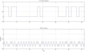
The Gold code is taken and the carrier is modulated according to the code as shown in Fig9. When the code input is binary 1, then the phase of the carrier remains as it is. When the input bit is 0 then the phase of the carrier is shifted by 180°.
Fig 9: BPSK Modulation
B. Channel
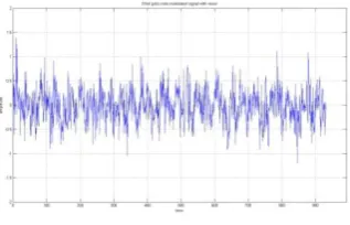
Fig 10:Noise added to BPSK Signal
C. Demodulation
The noise signal is received at the receiver and the original code is recovered from that signal as shown in Fig11.
Fig 11:Demodulated signal from noise signal
VI. MATLAB SIMULINK DESIGN
Fig 12: BPSK modulator
Fig 13: BPSK modulation
The basic type of modulation we selected for the design is the BPSK modulation. As mentioned in the literature survey the modulation and demodulation of the BPSK is performed according to the mentioned block diagram [8][9]
. It contains a modulator; here it is performed by a switch. The modulated signal is transmitted through an AWGN channel which outputs a noisy signal.
Fig 14: BPSK modulator with noise block
Fig 15: BPSK modulation with noise
Fig 16: BPSK demodulator
The modulated signal is passed through the AWGN channel. At the receiver the AWGN output signal is multiplied with the carrier that is taken in the input (coherent detection). The carrier multiplied output is given to integrate and dump receiver which integrates for 2samples. Integrate and dump receiver output is given to the Low pass filter.
Fig 17: BPSK demodulator outputs
According to the output from filter the switch will consider the output bit is Binary 1 or 0.
Fig 19: Comparison of input and output code The receiver section consists of a matched filter ie., the received noisy signal is multiplied by the same carrier used in transmitter. Such signal is given to integrate and dump receiver, which integrates the received signal for 2 sample intervals and it is passed to low pass filter. According to the design of the low pass filter the output waveform is delayed. The output switch detects the output bit according to the LPF output. The results are plotted using the scope.
VII.RESULTS
The Matlab simulations are performed using Matlab text editor. The code taken is the Gold code. Gold code is selected due to its good correlation properties. By using the code the simulations are performed [5][6]
.
In the Simulink design Fig15 shows the complete design which contains the modulator, channel and the demodulator. The outputs for each and every stage are shown with the design.
The Output code is compared with the input code so that the design is termed as apt for the BPSK modulation and demodulation.
VIII.CONCLUSION
The aim of the paper is to perform the Bit Error Rate analysis using Matlab Graphical User Interface., BERTool. Two types of simulations are performed, one is theoretical simulations and it is verified with the Monte Carlo design simulations.
Later on a BPSK system is simulated using the Matlab text editor. The design of the BPSK system in MATLAB Simulink is performed and all the results are plotted.
ACKNOWLEDGEMENT
By taking this as a pleasure we thank our guide VijayBhaskar chanda and I.hemalatha
REFERENCES
[1]. Simon Haykin, “Communication systems”, third edition,
John Wiley & sons (Asia) pte. Ltd.
[2]. Bernard Sklar, Pabitra Kumar Ray,”Digital Communications, Fundamentals and Applications”,
second edition, Pearson Education, Inc., 2001.
[3]. Taub, Schilling, “Principles of Communications Systems”, second edition, Tata McGraw-Hill publishing
Company Limited, New Delhi.
[4]. John G.Proakis, Masoud Salehi,”Contemporary Communication Systems using Matlab”, PWS publishing
company.
[5]. Nadav levanon, Eli Mozeson, “Radar signals” John
Wiley & sons Inc, 2004.
[6]. L Todd B. Hale, Michael A. Temple, and Benjamin L. Crossley, “Ambiguity Analysis for Pulse Compression Radar Using Gold Code Sequences”, Air Force Institute of Technology.
[7]. Meixia Tao, “Principles of Communications, Chapter 8: Digital Modulation Techniques”, Shanghai Jiao Tong University.
[8]. S.O. Popescu, A.S.Gontean and G.Budura , “BPSK System on Spartan 3E FPGA”, 10th IEEE Jubilee International Symposium on Applied Machine Intelligence and Informatics January 26-28, 2012.