R. K. Arief1 , Q. Nurlaila2 and Armila3
1Universitas Muhammadiyah Sumatera Barat, Padang
West Sumatera, Indonesia E-mail: [email protected]
2Universitas Riau Kepulauan, Batam
Kepri, Indonesia
E-mail: [email protected]
Comparative Study of Conventional and Quick Die Change Stamping
Process: The Issue of Setup Time and Storage
Rudi Kurniawan Arief, Qomarotun Nurlaila and Armila
Received: 16 September 2018 Accepted: 22 October 2018 Published: 01 December 2018 Publisher: Deer Hill Publications © 2018 The Author(s)
Creative Commons: CC BY 4.0
ABSTRACT
Metal stamping industry has Quick Die Change (QDC) as a form of Single Minutes Exchange of Dies (SMED) as an efficient production technique where the implementation depends on operator’s activities, clamping system, accessories type and position, etc. This QDC could apply to improve the process efficiency, control of inventory and reducing the cost. This research compared the traditional metal stamping process and QDC System (QDCS) of metal stamping. This research was using Focused Group Discussion (FGD), direct observation and experiments, conducted in a private metal stamping company in wider Jakarta region of Indonesia. It was observed that the QDCS significantly reduces setup time, storage space and the cost. The setup time and cost reduced to one third of the conventional and the requirement of storage decreased by 70%. In addition, QDCS reduces the waste significantly.
Keywords: SMED, QDC, Process Efficiency, Lean Manufacturing
1 INTRODUCTION
In the field of manufacturing industry especially metal stamping industry, the Single Minute Exchange of Die (SMED) founded by Shigeo Shingo during 1950’s is the most widely used [1]. SMED increased efficiency in metal stamping by moving the setup process of stamping die that usually held at the machine bed in outside area, which become a pre-set up process. Due to high production rate, product variability, short product’s lifecycle and inventories, the SMED technique become a popular method in metal stamping industries [2]. Later, this SMED technique also developed to other field of industry outside metal stamping.
Today’s trend required higher demand of product variation by the costumer. This has become a big problem for metal stamping company, since metal stamping required large quantity production to reduce the overall cost. Large product variation required frequent change of tools (die set) and low scale production than usual which make company to focus on process innovation [3]. The main focus of SMED is to eliminate wastes from tool setting activities by reducing the time less than 10 second [4]. In metal stamping industry, this SMED technique also called by Quick Die Change (QDC) with the concept of simplification of in-machine setup by the standardized activities and work sequence. Most of the QDC techniques associated with machine and tools accessories, operator’s activities such as clearing area, clamping, setting, etc. [5], which reduces the waste and save 75% time and 50% manpower [6].
2 QUICK DIE CHANGE
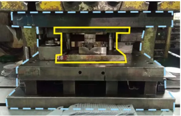
decreasing company’s expenses that modify the construction of metal stamping die. The concept of QDCS, in die construction point of view, is to separate main die or stamping function with the support function. Parts with die stamping function are grouping as one assembly named Quick Die Change Dies / QDCD and group of parts with support function as the other assembly named Quick Die Change Housing / QDCH as shown in Figure.1. In the construction of conventional die, supporting and main components construct as one big assembly as shown in Figure. 2. This cause higher cost to construct a die for a small component. With QDCS company only need to build the QDCD to be inserted into QDCH and QDCH may use for many of QDCD. This inserted and exchanging system of QDCS could save manufacturing cost for about 35% [8].
3 METHODOLOGY
This research is to investigate the advantages termed as “efficiency” that might gain from the implementation of QDCS. Investigation will include the efficiency gained from setup time, storage area and the cost for all of these. Main data are collected from direct observation and interview. Activities held in a metal stamping company near Jakarta wider region. Focused Discussion Group attended by manager and supervisor from department of Engineering, quality control and production of designated company. Time consumed by the operators to setup the dies has been counted and compared. Dimension of dies and the storages has been measured. Those two parameters have been converted into parameter of cost based to Indonesian currency (Rupiah / IDR).
Figure 1: Construction of QDCS. Blue dashed line is showing the construction of QDCH and yellow full line show the construction of QDCD.
4 ANALYSIS OF SETUP TIME EFFICIENCIES
The QDCS is the combination of QDCD and QDCH where QDCD is very light in weight so it can be carried by hand, while conventional dies must be carried by lifting device. Observation will count the setup time from picking up dies from the storage, positioning on the table, machine’s height setup (inching), clamping, unclamping and unloading out of the machine. These steps from each die construction have been compared.
4.1 Setup Time of Conventional Die
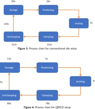
Time counted from the first operator picking up dies from storage in different room by forklift. Die operator then adjusted the position of dies according to applicable clamping groove. The machine height is adjusted to desired position and then operator start to clamps. Dies were unclamped after production process is finished and took by forklift operator to put back to storage area where located 10 meters away. Flow process shown by chart in Figure 3.
4.2 Setup Time of QDCH
QDCH must be setup before QDCD can be use. Setup time is similar to conventional die since QDCH has big construction as conventional die and placed in the same storage area. Setup process also similar to the conventional die.
4.3 Setup Time of QDC
QDCD as explained before will be placed inside of the QDCH, so the observation condition is where the QDCH already installed. QDCD has been picked up from the storage that located two meters away, and could pick up directly by hand. QDCD then easily positioned inside the QDCH with help of guide rail provided. Inching did not take long time because initial inching already done by setup of QDCH. Clamping devices have already been provided for quick clamping and unclamping activities. Setup and uninstall process is shown in Figure 4.
Figure 3: Process chart for conventional die setup
4.4 Setup Time Comparison
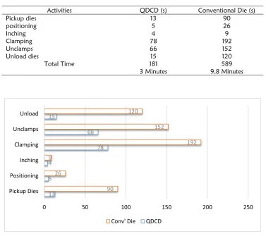
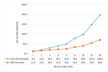
Table 1 explained the comparison of setup time between two systems. From data presented in Figure 5, shown huge differences between those two dies construction. QDCD setup is 69% faster compared to conventional die. However, QDCD is depends to QDCH, so setup time of QDCH must be added in order to know real efficiencies. Data above shown that using one QDC is less efficient (-30.61%) because combination setup time of QDCH and QDCD. However, after application of two QDCD that use directly after the first die, efficiency gap become wider. The increasing of gap percentages can be seen in Table 2 as well as in Figure 6.
Table 1: Comparison of setup time
Activities QDCD (s) Conventional Die (s)
Pickup dies 13 90
positioning 5 26
Inching 4 9
Clamping 78 192
Unclamps 66 152
Unload dies 15 120
Total Time 181 589
3 Minutes 9,8 Minutes
Figure 5: Setup time comparison chart
Table 2: Efficiencies comparison
Number of Die to be Installed
Sequentially Conv' Die (s) QDCS (s) Efficiency Percentages QDCS to Conv' Die
1 9,8 12,8 -30,61%
2 19,6 15,8 19,39%
3 29,4 18,8 36,05%
4 39,2 21,8 44,39%
5 49,0 24,8 49,39%
8 78,4 33,8 56,89%
10 98,0 39,8 59,39%
15 147,0 54,8 62,72%
13 5 4
78 66 15
90 26
9
192 152
120
0 50 100 150 200 250
Pickup Dies Positioning Inching Clamping Unclamps Unload
Figure 6: Efficiencies comparison’ chart, comparing setup time required for some number of dies.
4.4 Setup Time Cost Comparison
Setup process from the observation above then analysed into cost parameters. Manpower and machine rate will be calculated as the parameter of direct cost. Cost of electricity, maintenance, administration, factory rent, etc. will be ignorance. Since observation conducted in Indonesia the cost calculation will using IDR by assuming 1 USD = 14.000 IDR. Observed stamping process was conducted with 80 Tons manual stamping machine, operated by one person. Observed company is located in Kota Bekasi, an industrial city near Jakarta. Only net wage will be calculated outside any allowance might offer by the company to their labour. Current minimum labour wages (UMR) for manufacturing industry in this area in 2018 is 3.900.000 IDR with 26 days of working per month.
Lc = UMR / 26 days/ 8hour/ 60minutes (1)
= 3.900.000 /26 / 8/ 60 = 312,5 IDR / minute. Labour cost per minute is 312,5 IDR.
From Table 1, we have data of setup time for QDCS is 3 minutes (St1) and conventional die is 9,8 minutes (St2). Labour cost to performance the setup is Labour cost per minutes times setup time.
Sc1 = St1 x Lc (2)
= 3 min x 312,5 IDR = 937,5 IDR.
Sc2 = St2 x Lc (3)
= 9,8min x 312,5 IDR = 3.062,5 IDR.
Eg = Sc2 – Sc1 (4)
= 3.062,5 – 937,5 = 2,125 IDR.
Where, UMR= Current minimum labour wages, Lc= Labour cost (IDR/min), St1= setup time for QDCS (minutes), St1= Setup time conventional die (minutes), Sc1= setup cost for QDCS (IDR), Sc2= setup cost for conventional die
1 2 3 4 5 8 10 15 20
Conv Die (minutes) 9.8 19.6 29.4 39.2 49.0 78.4 98.0 147.0 196.0
QDC (minutes) 12.8 15.8 18.8 21.8 24.8 33.8 39.8 54.8 69.8
0.0 50.0 100.0 150.0 200.0 250.0
SE
T UP
T
IME
(MI
NUT
E)
Machine rate for 80 Tons stamping machine is 170 IDR per stroke, machine can perform 360 stroke per hour or 6 stroke per minute.
Spm = Sph/60 (5)
= 360/60 = 6 stroke/min.
Mc1 = St1 x Spm (6)
= 3 x 6 = 18 strokes.
Mf1 = Mc1 x Mr (7)
= 18 x 170 = 3.060 IDR.
Mc2 = St2 x Spm (8)
= 9,8 x 6 = 58,8 strokes.
Mf2 = Mc2 x Mr (9)
= 58,8 x 170 = 9.996 IDR.
Er = 100 % - (100% x (Mf2/Mf1)) (10)
= 100% - (100% x (3.060/9.996)) = 100% - 30,6%
= 69,4%.
Where, Sph= Stroke per hour, Spm= Stroke per minute, Mr= Machine rate, Mc1= Machine cost for QDCS, Mf1 = Machine fee for QDCS, Mc2= Machine cost for Conventional, Mf2= Machine fee for Conventional, Er= Efficiency rate. Converting to machine rate QDCD setup cost is 3.060 IDR and conventional die 9.996 IDR. QDCD successfully reduced direct cost by 69,4% compared to conventional die. Summary of cost calculation is presented in Table 3.
Table 3: Cost efficiencies comparison
Parameters QDCS Conventional
Manpower 938 IDR 3.063 IDR
Machine Rate 3.060 IDR 9.996 IDR
Total Cost 3.998 IDR 13.059 IDR
5 ANALYSIS OF STORAGE EFFICIENCIES
SMED technique not just increase productivity and reduce cost but also able to reducing inventories [2]. QDCD built with smaller size due to it’s insertable function while QDCH is same in size but less height than the conventional die. The QDCH only require 1 unit for each stamping machine, so the quantity is very less and QDCD will be more because manufactured 1 unit for each process. The size of QDCD and QDCH is already standardized and conventional die will be analysed with minimum size that can be build. Analyses is doing by simulating the data taken accordingly to the situation in designated company that owned 80 units of QDCD, 5 units of QDCH and hundreds of conventional dies. Analysis conducted by simulating the storage for 80 unit of dies.
Table 4: Storage comparison for 80 units QDCS and Conventional die
A B C D E F G H =FxG I J=HxI
Die
Type Die Size (mm)
Space required
(mm)
Storage Rack (80 Dies)
Space Dimension
(mm)
Total Space (M)
Rent pe Meter
(IDR)
Monthly Rent Fee (IDR) Row Column Width Length
QDCD 250 x 200 x 150
350 x 300 x
250 5 16 300 5.600 1.680 40.000 67.200.000
Con'v Die
500 x 360 x 300
600 x 460 x 450
4 20 460 12.000 5.520 40.000 220.800.000
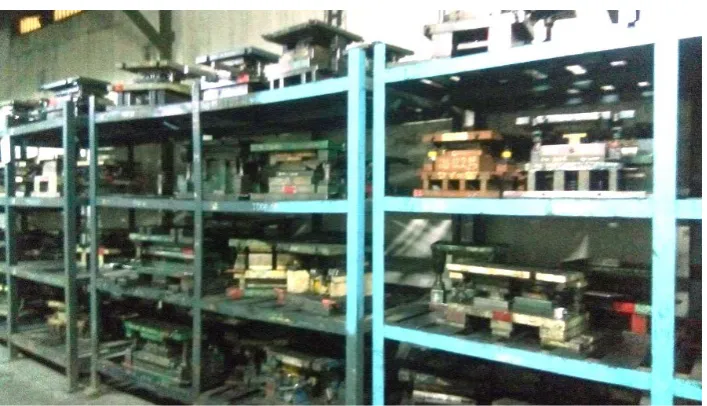
Figure 7: Storage for QDCD
5 CONCLUSIONS
From the observation and analysis above QDCS could make efficiencies up to 70% compares to conventional die. Amount of 153.000.000 IDR might be saved by the sleek design of QDCS from storages area, so some other wide storage spaces may be used for other productive activities. But company must pay attention for production arrangement where this QDCS must be employed sequentially for at least two QDCD, otherwise efficiently of process may decrease to 31%. The QDCS must be employed sequentially in order to gain higher efficiency. With amount of efficiency achieved and plenty of money saved, metal stamping industry should be considering this system for their efficiency effort to produce more variable products with lower amount of quantity in a reasonable price.
ACKNOWLEDGEMENT
This research was funded by Ministry of Research, Technology and Higher Education Indonesia under Research Grant scheme of Penelitian Dosen Pemula 2018 (Project Number: 013/Kontrak-Penelitian/LPPM-UMSB/2018). The authors are grateful to the management team and employees of PT. Sanwa Presswork Indonesia where most of this research activities took place. This is the enhancement version of previous conference paper that has been submitted to CITES 2018 International Conference.
REFERENCES
1. Shingo, S. (1985). A Revolution in Manufacturing: The SMED System. Productivity Press, Oregon.
2. Yash, D. & Sohani, N. (2012). Single Minute Exchange of Dies: Literature Review. International Journal of Lean Thinking, Volume 3, Issue 2.
3. Moreira, A. C., Pais, C. G. S., (2011). Single Minute Exchange of Die. A Case Study Implementation. Journal of Technology Management & Innovation, Volume 6, Issue 1.
4. Abraham, Ganapathi K. N., Motwani, K. (2012). Setup Time Reduction through SMED Technique in a Stamping Production Line. SAS Tech Journal, Volume 11, Issue 2, Sep 2012.
5. Solehah, S (2013). Design and Development of SMED Quick Die Change Tools for Small Press Dies. University Malaysia Pahang, Malaysia.
6. Yamaguchi, F. (2013). Phillipine Metal Stamping Sector Study 2013. Jaoan Metals Industry Research and Development Center and Philipine Departemen of Science and Technology, Taguing City.
7. Arief, R. K. (2018). Time and Cost Efficiency Analysis of Quick Die Change System on Metal Stamping Industry.World Academy of Science, Engineering and Technology, International Journal of Industrial and Systems Engineering, Vol:12, No:2, 2018. dai:10.1999/1307-6892/10009095.
8. Suchy, I. (2006). Handbook of Die Design”. New York, McGraw-Hill.

![The Renewable Energy Progress Report: Commission Report in accordance with Article 3 of Directive 2001/77/EC, Article 4(2) of Directive 2003/30/EC and on the implementation of the EU Biomass Action Plan, COM (2005) 628 [SEC (2009) 503 final]. COM (2009) 1](data:image/gif;base64,R0lGODlhAQABAIAAAP///wAAACH5BAEAAAAALAAAAAABAAEAAAICRAEAOw==)