https://doi.org/10.5194/ms-8-369-2017
© Author(s) 2017. This work is distributed under the Creative Commons Attribution 3.0 License.
The design formulae for skew line gear wheel
structures oriented to the additive manufacturing
technology based on strength analysis
Yueling Lyu, Yangzhi Chen, and Yifan Lin
School of Mechanical and Automotive Engineering, South China University of Technology, Guangzhou 510640, China
Correspondence:Yangzhi Chen ([email protected])
Received: 30 March 2017 – Revised: 26 August 2017 – Accepted: 10 November 2017 – Published: 14 December 2017
Abstract. In this paper, the design methodology for a skew line gear pair oriented to additive manufacturing technology, with an one-tooth driving line gear and its coupled driven line gear, used for the conventional pow-ered transmission, is researched based on strength analysis. First, the expressions of meshing forces on the line tooth of line gears are deduced; the deformations and stresses of existing structures of a line gear pair are ana-lyzed by using ANSYS Workbench. Then, the reliable structure and the parameters standardization formulae of a line gear pair are deduced by stiffness and strength analyses. Finally, a design case shows that the proposed de-sign methods provide a convenient and reasonable dede-sign tool for dede-signing a skew line gear pair in conventional powered transmission field.
1 Introduction
A Line Gear (LG), based on the space curve meshing the-ory, is an innovative gear proposed by Yangzhi Chen (Chen, 2014). With a large transmission ratio, light weight and small size, a LG pair is mainly applicable to small and micro me-chanical systems, such as: toy industry, instruments and ap-paratus and new energy installation. The LG was also named as Space Curve Meshing Wheel (SCMW) or Micro Elastic Meshing Wheel (MEMW) in previous studies, including the Micro-elastic Meshing Wheel (MEMW) (Chen et al., 2009), Arbitrary Intersecting Gear (AIG) (Chen et al., 2013a) and Space Curve Meshing Skew Gear (SCMSG) (Chen et al., 2013b). The previous researches mainly focused on MEMW and AIG covering their meshing theory, manufacture tech-nology, geometric design formula, sliding rate, strength anal-ysis and transmission error analanal-ysis (Chen, 2014).
Strength analysis is an integral part of any mechanical de-sign, especially for gear (Patil et al., 2014; Huang et al., 2013; Pedrero et al., 2007; Chang et al., 2000; Wei et al., 2011). Similarly, strength analysis for line gear wheel is also essen-tial, especially for the line gear pair applied in the traditional machine, because the existing structure of the line gear pair
is easy to be deformed in application of large transmission torque of traditional machine (Chen, 2014; Chen et al., 2009, 2013a, b). When the number of the line tooth of a driving line gear is 1, a line gear pair can obtain bigger transmission ratio. However, the length of the line tooth increases because the contact ratio must be more than 1 (Chen and Chen, 2012; Lv et al., 2015), which means the strength and stiffness of the line gear are not enough to work, and a new structure of the line gear wheel needs to be designed on demand. Ad-ditive Manufacturing technology (Frederik et al., 2013) has been developing rapidly in the past decades. It is widely used because it can produce a variety of shapes of products, and its manufacturing cost is proportional to the real weight of the product. Additive manufacturing technology is used as a main manufacturing technology for the LG so far (Yang et al., 2009).
different meshing points are deduced. Then the deformations and stresses of the existing structure of the line gears, when the number of the line tooth of a driving line gear is 1, are analyzed by using ANSYS Workbench. Moreover, the driven line gear wheel structure is optimized using less material as design objective, namely, the design formula of the thickness of a hollow truncated cone on the basis of the stiffness cri-terion is deduced, and the calculation formula of the thick-ness of the optimal ribbed slab is derived on the basis of the strength criterion, and the experience formulae of the thick-nesses of a top circle plate and a bottom circle plate are de-duced. Then, the calculation formulae of the driving line gear wheel are deduced according to the strength and stiffness cri-terion. Finally, an example is designed to confirm the ratio-nality of the standardization formulae. This paper provides a basic theory for the skew line gear pair applied in conven-tional powered transmission field.
2 The meshing forces of a line gear pair
According to previous work of co-author (Chen and Chen, 2012), the equation of contact ratioεis1t N1/(2π) , where
N1is the number of a driving line tooth;1tis the design
pa-rameter of line gear. Therefore, if the number of a driving line toothN1equals to 1 and the contact ratio of a line gear pair
is more than 1, the design parameter1t should be equal to 2π, and the length of line teeth is much longer. Supposec=
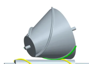
12 mm, θ=155◦,m=5 mm, n=6 mm, a=36.2373 mm, b= −58.8615 mm, ts= −3.5π,N1=1 and1t=2π, then
a line gear pair is designed, as shown in Fig. 1. In the follow-ing discussion, the subscript 1 refers to the drivfollow-ing line gear while 3 refers to the driven line gear.
2.1 The meshing forces on a driving line tooth
Suppose a given power isP, and a rotating speed isω1, then
the torque can be obtained:
T1=
P ω1
(1)
For a driving line tooth, the radius of torque is RT1, and
RT1=m, so the meshing force on the driving line tooth at
the meshing point is:
F1=
T1
RT1
(2)
The value of the meshing force on the direction of the bi-normal vector on a driving line tooth is as Eq. (3) and its direction is contrary to the direction of the binormal vec-tor, whereλ1is the helix height of the driving contact curve,
λ1=arctan(n/m).
Fn=F1sinλ1 (3)
Figure 1.A skew line gear pair when the number of driving line tooth is 1.
The direction of the binormal vector of a driving tooth is as Eq. (4), wheretis parameter in the range of thatts≤t≤te.
r(1)=
nsint
√
n2+m2
−ncost
√
n2+m2
m
√
n2+m2
(4)
The meshing force on a driving line tooth at the meshing point is as Eq. (5).
Fn(0)=Fnr(1) (5)
Substituting Eq. (4) into Eq. (5), Eq. (6) can be obtained.
F(0)n =Fn
−nsint
√
n2+m2
ncost
√
n2+m2
−m
√
n2+m2
(6)
2.2 The meshing force on a driven line tooth
Eq. (7).
F(1)3 =Fn
nsint
√
n2+m2
−ncost
√
n2+m2
m
√
n2+m2
(7)
The meshing force’s expressionF3(q)on a driven line tooth in o3−x3y3z3is obtained as Eq. (8).
F(3q)=M31Fn
nsint
√
n2+m2
−ncost
√
n2+m2
m
√
n2+m2
(8)
WhereM31=M3qMq1;φ1andφ3are the rotational angle
of the driving and driven line gear, respectively; in Chen et al. (2013b), when 0◦< θ <90◦, then,
M31=
−cosθcosφ3cosφ1+sinφ3sinφ1 −cosθcosφ3sinφ1−sinφ3cosφ1
−cosθsinφ3cosφ1−cosφ3sinφ1 −cosθsinφ3sinφ1+cosφ3cosφ1
sinθcosφ1 sinθsinφ1
0 0
−sinθcosφ3 (−acosθ+bsinθ) cosφ3−csinφ3
−sinθsinφ3 (−acosθ+bsinθ) sinφ3−ccosφ3
−cosθ asinθ+bcosθ
0 1 (9)
when 90◦< θ <180◦, then
M31=
−cosθcosφ3cosφ1−sinφ3sinφ1 −cosθcosφ3sinφ1+sinφ3cosφ1
cosθsinφ3cosφ1−cosφ3sinφ1 cosθsinφ3sinφ1+cosφ3cosφ1
sinθcosφ1 sinθsinφ1
0 0
−sinθcosφ3 (−acosθ+bsinθ) cosφ3−csinφ3
sinθsinφ3 (−acosθ+bsinθ)(−sinφ3)−ccosφ3
−cosθ asinθ+bcosθ
0 1 (10)
According to the space curve meshing theory (Chen et al., 2013b), a space curve meshing equation can be obtained as Eq. (11) from a given driving contact curve equation.
ccosθcos(φ1−t)−acosθsin(φ1−t)
−(nπ+nt−b) sin(φ1−t)=0 (11)
Substituting Eqs. (9) and (10) into Eq. (8), Eqs. (12) and (13) can be obtained. When 0◦< θ <90◦,
F(3q)=Fn
sin(φ1−t)ncosθcosφ3
√
n2+m2 +
cos(φ1−t)nsinφ3
√
n2+m2 −
msinθcosφ3
√ n2+m2
sin(φ1√−t)ncosθsinφ3
n2+m2 −
cos(φ√1−t)ncosφ3
n2+m2 −
m√sinθsinφ3
n2+m2
−sin(√φ1−t)nsinθ n2+m2
−√mcosθ n2+m2
(12)
when 90◦< θ <180◦,
F(3q)=Fn
sin(φ1−√t)ncosθcosφ3
n2+m2
−cos(√φ1−t)nsinφ3 n2+m2
−m√sinθcosφ3 n2+m2
−sin(φ1√−t)ncosθsinφ3 n2+m2 −
cos(φ1−t)ncosφ3
√
n2+m2 +
msinθsinφ3
√ n2+m2
−sin(√φ1−t)nsinθ n2+m2 −
mcosθ √
n2+m2
(13)
2.3 Deformation of the existing structure for a line gear pair
In Fig. 1, suppose the torque of a driving line gear is 2 N m, andRT1=5 mm, then the meshing force’s value on the
driv-ing line gear isF1=400 N, and the meshing force’s value on
the direction of the binormal vector on the driving line tooth at the ending meshing point is 2.779429 N, which ino1−
x1y1z1 is [−213.5216 N 3.9223×10⁻¹⁴N −177.9347 N].
The meshing force on the direction of the binormal vector on the driven line tooth at the initial meshing point ino3−x3y3z3
is [−116.1131 N−161.5928 N 194.0561 N]. The material of the following line gear is structural steel and its mechanic properties areE=2.0×10¹¹Pa,µ=0.3,σs=2.6×10⁸Pa.
The statics analysis results on the driving and the driven line gears are shown in Fig. 2 by using ANSYS Workbench. Their boundary conditions are the fixed upper surface of the line gear wheels. The load distribution are applied on the end of the tines.
In Fig. 2, the maximum deflection of the driving line gear is 0.316 m, and the maximum equivalent stress is 5.884×
1010Pa, while the maximum deflection of the driven line gear is 0.22902 m, and the maximum equivalent stress is 2.8469×10¹⁰Pa. It can be concluded that the deflections of line gears are so large and beyond elastic deformation al-lowance that the line gear pair cannot meet the transmission requirement. Therefore, a new structure for a line gear pair must be proposed to improve the stiffness of line gear and to ensure the transmission accuracy in traditional powered transmission field. The design methods and formulae of the line gear wheels in this paper are researched oriented to ad-ditive manufacturing technology.
3 Novel structures for the line gear wheel oriented to additive manufacturing technology
The number of the driving line tooth is 1 in this paper. Ac-cording to Sect. 2.3, it can be concluded that the stiffness of the structure of a line gear pair is so low that the line gear pair cannot meet the transmission requirement, which was designed as a structure in Fig. 1.
Figure 2.Statics analysis of a skew line gear pair with existing structure.
Figure 3. The structures of line gear pair are proposed in entity type.
However, oriented to the additive manufacturing technol-ogy, the greater the weight of the wheel is, the greater its production cost is. Therefore, under meeting the requirement of stiffness and strength, it can be considered to remove part of material from the entity structure of the line gear wheel in order to reduce the manufacturing cost of the line gear. With-out doubt, it can directly use the entity type as structure of
Figure 4.A hollow truncated cone is designed as a driven line gear wheel structure.
3.1 The influence of wall thickness of a hollow truncated cone on the stiffness of a line gear
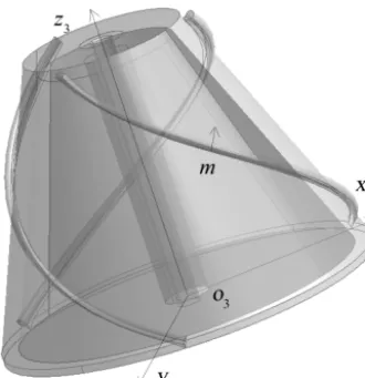
3.1.1 The force analysis on the hollow truncated cone of a driven line gear
Without considering the structure and size of a ribbed slab, wall thickness δ of a hollow truncated cone is discussed in this section. In Fig. 4, the meshing force of driven line gear is different with the meshing point m as analyzed in Sect. 2. Suppose top surface 1 and bottom surface 2 of a hollow circu-lar cylinder are fixed, according to force translation theorem of theoretical mechanics, the forces and the moments on the axis of the designated cross section, which are equivalent to the meshing forces, are obtained as Eqs. (14)–(16).
Fx1=
Fx3zm3+Fz3|xm3|
l3
Fx2=
Fx3(l3−zm3)−Fz3|xm3|
l3
Mx1=
(Fx3zm3+Fz3|xm3|)(l3−z3)
l3
Mx2=
(Fx3(l3−zm3)−Fz3|xm3|)z3
l3 (14)
Fy1=
Fy3zm3+Fz3|ym3|
l3
Fy2=
Fy3(l3−zm3)−Fz3|ym3|
l3
My1=
(Fy3zm3+Fz3|ym3|)(l3−z3)
l3
My2=
(Fy3(l3−zm3)−Fz3|ym3|)z3
l3 (15)
Fz1=
Fz3zm3
l3
Fz2=
Fz3(l3−zm3)
l3
T =
q
Fx23+Fy23
q
x32+y32
(16)
In Eqs. (14)–(16), the subscript of the subscript 1 refers to the top surface 1 of a hollow circular cylinder in Fig. 4, while the subscript 2 refers to the bottom surface 2 of a hollow circular cylinder in Fig. 4.
According to Eqs. (14)–(16), the strength and stiffness of the line gear wheel at different meshing point can be obtained by analysis.
3.1.2 The stiffness analysis of the hollow truncated cone of a driven line gear
The total deformation of the hollow truncated cone consists of the deformations generated by the bending moment, the torque and the axial force, respectively. The deflection equa-tions generated by the bending moment in different direc-tions are shown in Tables 1 and 2.
Because the results are too complex and not necessary, by substituting of different values ofIx3in different cross
sec-tions of a hollow truncated cone into formulae in Tables 1 and 2,Ix3with a fixed minimum value is set which can make
the deformation maximum in this paper. By comparing this maximum deformation with an allowable material stiffness value, the wall thicknessδof the hollow truncated cone can be obtained. Meanwhile, its value is relatively safe. By this way, the deflection calculation formulae are shown in Ta-bles 3 and 4.
The deformation generated by the torque is obtained as Eq. (17).
1φ= T
GIρ3
=
q
Fx23+Fy23
q
x32+y32
GIρ3
(17)
The deformation generated by the axial force is obtained as Eq. (18).
1z21=
Z −zm
−zte
Fz1
EAz3
dz= Fz3zm3z3
El3(π(R32−(R3−δ)2))
1z22=
Z 0
−zm
Fz2
EAz3
dz= Fz3(l3−zm3)z3
El3(π(R32−(R3−δ)2))
(18)
Where,Ix3=
π δ2(R32+(R3−δ)2)
4 =Iy3,Iρ3=
π δ2(R32+(R3−δ)2)
2 .
Suppose the allowable deflection values of the hollow truncated cone of a driven line gear inx3,y3,z3directions
Table 1.The deflection equation of the driven line gear inx3axis.
1-m part m-2 part
EIx3ω¨x1=Mx1 EIx3ω¨x2=Mx2
˙ ωx1=
R−zm
−zte
Mx1
EIx3dz+Cx1 ω˙x2=
R−zts
−zm
Mx2
EIx3dz+Cx2 ωx1=
R−zm
−zte(
R−zm
−zte
Mx1
EIx3dz+Cx1)+Dx1 ωx2=
R−zts
−zm(
R−zts
−zm
Mx2
EIx3dz+Cx2)+Dx2
Table 2.The deflection equation of the driven line gear iny3axis.
1-m part m-2 part
EIy3ω¨y1=My1 EIy3ω¨y2=My2
˙ ωy1=
R−zm
−zte
My1
EIy3dz+Cy1 ω˙y2=
R−zts
−zm
My2
EIy3dz+Cy2 ωy1=
R−zm
−zte(
R−zm
−zte
My1
EIy3dz+Cy1)+Dy1 ωy2=
R−zts
−zm(
R−zts
−zm
My2
EIy3dz+Cy2)+Dy2
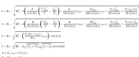
and 4, Eqs. (17) and (18), Eq. (19) can be obtained.
δ > R3−4 v u u tR4
3−4
A π 1xEl3
l3z2 m3 2 − z3 m3 6 ! − A
3Eπ[1x]l3zm3− Az2
m3
6El3π[1x]zm3+ Fx3z3
m3
6Eπ[1x]+ Fz3z2
m3|x3|
2Eπ[1x]
!
δ > R3−4 v u u tR4
3−4
B El3π[1x]
lz2 m3 2 − z3 m3 6 ! − B
3Eπ[1x]l3zm3−
Bz2 m3
6El3π[1x]
zm3+
Fy3z3 m3
6Eπ[1x]+ Fz3|y3|z2
m3
2Eπ[1x]
!
δ > R3− s
R2 3−
F
z3(l3−zm3)
El3
(zm3)
/(π[1z])
δ > R3−4
r
R4 3−2(
q
F2 x3+Fy23)
q
x2 3+y32/(Gπ[1θ])
A=Fx3zm3+Fz3|x3| B=Fy3zm3+Fz3|y3|
(19)
According to Eq. (19), the stiffness of the hollow truncated cone can meet the requirement.
From Fig. 1, suppose the torque of a driving line gear is equal to 2 N m, the forces and the deformations of the driven line gear wheel at different meshing point are analyzed by MATLAB, and their results are shown in Fig. 5.
Figure 5a shows the component forces’ values in three axes at different meshing points; Fig. 5b shows the defor-mations generated by the axial force at different meshing points; Fig. 5c shows the bending deflections at different meshing points; Fig. 5d shows the deformation generated by the torque at different meshing points. From Fig. 5a, the com-ponent forces inx3,y3andz3axes at the meshing point are
not equal to one another, the changes of component forces in the x3 andy3 axes are periodic while the change of
com-ponent force in the z3 is monotonically increasing. From
Figs. 5b–d, it is indicated that the deformation generated by the torque is maximum, and its value is 3 and 16 order of magnitudes higher than other two deformations, respectively. To simplify the calculation, the effects of the torque defor-mation on the driven wheel can only be considered, namely, the wall thickness of the hollow truncated cone only needs to
meet Eq. (20).
δ > R3−
4 v u u t
R34−2
q
Fx23+Fy23
q
x32+y32
Gπ[1θ] (20)
3.2 The structure design of ribbed slab structure
For more improving of the stiffness of the line gear wheel, a ribbed slab can be added between the hollow truncated cone and the hollow circular cylinder, as shown in Fig. 6. The followings discuss the structure selection and the size determination of a ribbed slab. The material of the follow-ing line gear is structural steel and its mechanic properties areE=2.0×10¹¹Pa, µ=0.3,ρ=7.85 g cm−3,σs=2.6×
108Pa. Their boundary conditions are the fixed upper and lower surfaces of the line gear wheels. The load distribution are applied on middle meshing point of the line teeth.
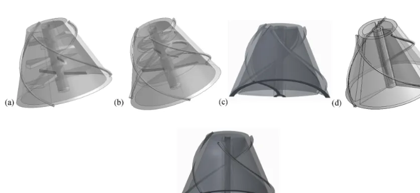
3.2.1 The structure selection of a ribbed slab
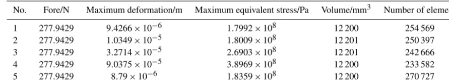
In this paper, five types of the ribbed slab structures are proposed and analyzed, as shown in Fig. 6; their volumes are equivalent, their maximum deformations and maximum equivalent stresses are analyzed by using ANSYS Work-bench software, and then the optimal ribbed slab structure is determined. A ribbed slab structure in Fig. 6a consists of 5 layers of support plates: a top and a bottom circle plates and other 3 layers which every layer consists of 3 sector plates, whose sector plate’s angle is equal to 45◦and the midpoint
Figure 5.The forces and the deformations of the driven line gear wheel at different meshing points.
Table 3.The calculation formulae of the driven line gear inx3axis.
1-m part m-2 part
ωx1=
(Fx3zm3+Fz3|x3|)(3l3z23−z33)
6EIx3l3 −
Fx3zm3+Fz3|x3|
3EIx3 l3z3 ωx2=
(Fx3(l3−zm3)−Fz3|x3|)(z33)
6EIx3 −
Fz3|x3|z2m3
2EIx3l3 z3 −Fx3z
3
m3+3Fz3zm23|x3|
6EIx3l3 z3+
Fx3z3m3
6EIx3 +
Fz3z2m3|x3|
2EIx3 −
Fz3zm3|x3|
EIx3l3 z3−
Fx3z3m3
6EIx3l3z3−
Fx3zm3l3
3EIx3 z3−
Fz3|x3|
3EIx3l3z3+
Fx3z2m3
2EIx3 z3
Table 4.The calculation formulae of the driven line gear iny3axis.
1-m part m-2 part
ωy1=
(Fy3zm3+Fz3|y3|)(3l3z23−z 3 3)
6EIy3l3 −
Fy3zm3+Fz3|y3|
3EIy3 l3z3 ωy2=
(Fy3(l3−zm3)−Fz3|y3|)(z33)
6EIy3l3 −
Fz3|y3|z2m3
2EIy3l3 z3 −Fy3z
3
m3+3Fz3zm23|y3|
6EIy3l3 z3+
Fy3z3m3
6EIy3 +
Fz3z2m3|y3|
2EIy3 −
Fz3zm3|y3|
EIy3 z3−
Fy3z3m3
6EIy3l3z3−
Fy3zm3l3
3EIy3 z3−
Fz3|y3|
3EIy3l3z3+
Fy3z2m3
2EIy3 z3
truncated cone; a ribbed slab structure in Fig. 6c is a im-peller structure scanning by the driven center curve and shaft directly; a ribbed slab structure in Fig. 6d consists of 3 fan support plates which continuously support the hollow trun-cated cone; a ribbed slab structure in Fig. 6e consists of a im-peller structure scanning by the driven center curve and shaft directly, and a top and a bottom circle plates. The lower of the models in Figs. 6c and d are partially fractured and their cross sections are shown gray part. The maximum defor-mations and the maximum equivalent stresses of the driven line gears at middle meshing point are analyzed by ANSYS Workbench, as shown in Table 5.
From Table 5, that can be concluded the ribbed slab struc-ture in Fig. 6e is the optimal.
3.2.2 Design formula of the ribbed slab on the basis of the strength criterion
The shape of the cross section of a driven line gear wheel in Fig. 6e is shown in Fig. 7. Supposeζ is the thickness of the ribbed slab, according to the strength criterion, thenζ can be obtained.
According to Sect. 2, the bending moment, the torque and the axial force can be obtained, and the stresses generated by them are calculated by Eqs. (21)–(23).
τFx1 =
Fx3zm3+Fz3|xm3|
Am3l3
τFx2 =
Fx3(l3−zm3)−Fz3|xm3|
Am3l3
σMx1 =
Fx3zm3+Fz3|xm3|
Iy3l3
(l3−z3)Rm3
σMx2 =
Fx3(l3−zm3)−Fz3|xm3|
Iy3l3
(z3)Rm3
(21)
Figure 7.The cross section shape of a driven line gear in Fig. 6e.
τfy1 =
Fy3zm3+Fz3|ym3|
Am3l3
τfy2 =
Fy3(l3−zm3)−Fz3|ym3|
Am3l3
σMy1 =
Fy3zm3+Fz3|ym3|
Ix3l3
(l3−z3)Rm3
σMy2 =
Fy3(l3−zm3)−Fz3|ym3|
Ix3l3
(z3)Rm3
(22)
τT =
q
Fx23+Fy23
q
x32+y32
Iρ3
Rm3
σFz1 =
Fz3zm3
Am3l3
σFz2 =
Fy3(l3−zm3)
Am3l3
Table 5.The statics analysis results for five types of ribbed slab structures at middle meshing point.
No. Fore/N Maximum deformation/m Maximum equivalent stress/Pa Volume/mm3 Number of element
1 277.9429 9.4266×10⁻⁶ 1.7992×10⁸ 12 200 254 569 2 277.9429 1.0349×10⁻⁵ 1.8009×10⁸ 12 201 250 397 3 277.9429 3.2714×10⁻⁵ 2.6903×10⁸ 12 201 242 666 4 277.9429 9.0375×10⁻⁵ 3.8969×10⁸ 12 200 233 582 5 277.9429 8.79×10⁻⁶ 1.8359×10⁸ 12 200 270 727
where,Am3=π(R2m3−(R3−δ)2)+π(R2z3−rz23)+3ζ(R3−
δ−Rz3). According to Sect. 2.1,δcan be decided. Because
the shape of the cross section of a driven line gear wheel is ir-regular, the calculations of the inertia moment and the polar moment of inertia are relatively complex. Using the calcu-lation method that the irregular cross section is divided into several regular sections, the inertia moment and the polar mo-ment of inertia in Eqs. (21)–(23) can be obtained by using Eqs. (24)–(26).
Iy3=
Z
x32dA=π δ
2(R2
3+(R3−δ)2)
4 +
π(R4z3−rz43)
4
+ζ((R3−δ)−Rz3)
3
2 (24)
Ix3=
Z
y32dA=π δ
2(R2
3+(R3−δ)2)
4 +
π(R4z3−rz43)
4
+ζ((R3−δ)−Rz3)
3
2 (25)
Iρ3=
π δ2(R32+(R3−δ)2)
2 +
π(Rz43−rz43)
2 +ζ((R3−δ)−Rz3)
3
(26)
The shear stresses generated by two component forces inx3
andy3axes respectively are relatively so small that they can
be ignored. According to knowledge of material mechanics, comprehensively considering the bending moment, the axial force and the torque, the dangerous section of a driven line gear wheel may occur in the force bearing point, because this point bears the biggest bending moment. Meanwhile it bears the axial force and torque. Therefore, in the maximum stress point, the stress state is 2-D stress produced by the bending moment, the torque and the axial force, as shown in Fig. 8.
The principal stresses can be obtained by using Eq. (27).
σ1
σ3
)
=
q
σy2+σx2+σFz
2 ± v u u u u t q
σy2+σx2+σFz
2
2
+τT2
(27)
Figure 8.The diagram of shear stress and normal stress of maxi-mum stress unit point.
According to the maximum shear stress theory (James and Barry, 2011), Eq. (28) can be obtained.
σ1−σ3≤
σs
ns
(28)
According to Eqs. (21)–(24), Eq. (29) can be obtained.
σ1 σ3 ) = r C Ix3l3(l3−zm3)Rm3
2
+
D Iy3l3(l3−zm3)Rm3
2
+Fz3zm3 Am3I3
2 ± v u u u u u u t r C Ix3l3(l3−zm3)Rm3
2
+
D Iy3l3(l3−zm3)Rm3
2
+Fz3zm3 Am3l3
2 2 + q F2 x3+F
2 y3 q x2 3+y 2 3
Iρ3
Rm3 2
C=Fy3zm3+Fz3|ym3| D=Fx3zm3+Fz3|xm3|
(29)
Substituting Eq. (29) into Eq. (28), Eq. (30) can be obtained.
2 v u u u u u u t r C Ix3l3(l3−zm3)Rm3
2
+
D Iy3l3(l3−zm3)Rm3
2
+Fz3zm3 Am3l3
2 2 + q F2 x3+Fy23
q
x2 3+y23
Iρ3
Rm3 2
≤σs ns
C=Fy3zm3+Fz3|ym3| D=Fx3zm3+Fz3|xm3|
(30)
Using Eqs. (27)–(30), the minimum thickness of a ribbed slab can be obtained.
3.3 The design formulae of the thicknesses of a top circle plate and a bottom circle plate
Table 6.The statics analysis results at middle meshing point, without equivalent thicknesses of a top circle plate and a bottom circle plate
No. Fore/N Maximum Maximum equivalent Volume Thickness of Thickness of Number of deformation/m stress/Pa /mm3 upper plate/mm lower plate/mm element
1 277.9429 8.2071×10⁻⁶ 1.8762×10⁸ 12 198 0.8 0.8 274 546 2 277.9429 6.1809×10⁻⁶ 1.3742×10⁸ 12 199 1.8 0.695 271 378 3 277.9429 5.7629×10⁻⁵ 1.3722×10⁸ 12 198 2.635 0.6 264 901 4 277.9429 5.7386×10⁻⁶ 1.4917×10⁸ 12 199 0.5 3.43 261 578 5 277.9429 8.697×10⁻⁶ 1.9875×10⁸ 12 200 0.695 0.812 271 905 6 277.9429 9.3746×10⁻⁶ 2.0093×10⁸ 12 201 0.6 0.6 270 727 7 277.9429 7.7317×10⁻⁶ 1.6682×10⁸ 12 200 0.717 0.717 268 402
for a design of equivalent volume of the driven line gear wheel, and the equivalent wall thickness of the hollow trun-cated cone. Meanwhile, a larger additional wind loads may be produced by the high speed rotating of the driven line gear wheel, with a structure in Fig. 6c, that may cause the harmful effects such as vibration and noise. In this section, the design formulae for the thicknesses of a top circle plate and a bottom circle plate are deduced.
The statics analysis results at middle meshing point, with-out equivalent thicknesses of a top circle plate and a bottom circle plate, are shown in Table 6.
According to Table 6, when thickness of a top circle plate is large than the thickness of a bottom circle plate, the max-imum deformation and the maxmax-imum equivalent stress of a driven line gear are the smallest. Therefore, in this paper, the relationship between the thickness of the top circle plate η and thickness of a bottom circle plateξ is set asη=4ξ, while the relationship betweenξ and height of a driven line gear wheel is set asl3=60ξ.
3.4 Design of a hollow circular cylinder for the installation of the driven axis
The inner diameter of a hollow circular cylinder depends on the output torque. When the inner diameter of a hollow cir-cular cylinderrz3<(R31−s)−5, the structure of the driven
line gear wheel can be designed as a structure shown in Fig. 6e, and an outer diameter of the hollow circular cylin-der isRz3=rz3+3; but for that caserz3≤(R31−s)−5, the
structure of a driven line gear wheel can be designed in the entity type.
3.5 The calculation formulae for the stiffness and strength of a driving line gear wheel
A driving line gear wheel is designed as an entity type, namely, it is a cylinder. The driving line tooth is ignored, and only the wheel is considered here, then its strength cal-culation formulae can be also from Tables 3, 4, Eqs. (17) and (18). Because its cross section shape is not equivalent to a driven line gear wheel, its inertia moment and the polar mo-ment of inertia can be calculated byIx1=Iy1=π R41/4 and
Iρ1=π R14/2, respectively. Its maximum deformation can be
calculated by Eqs. (31)–(35).
1y=4(Fx1zm1+Fz1|xm1)(3l1z
2 m1−z
3 m1)
6El1π R14
−4Fx1zm1+Fz1|xm1| 3Eπ R14 l1zm1
−4Fx1z
3
m1+3Fz1z 2 m1|xm1|
6El1π R14
zm1
+4Fx1z
3 m1
6Eπ R14
+4Fz1z
2 m1|xm1|
2Eπ R41 (31)
1x=4(Fy1zm1
+Fz1|ym1)(3l1z2m1−z3m1)
6El1π R14
−4Fy1zm1+Fz1|ym1| 3Eπ R14 l1zm1
−4Fy1z
3
m1+3Fz1z 2 m1|ym1|
6El1π R14
zm1
+4Fy1z
3 m1
6Eπ R41
+4Fz1z
2 m1|ym1|
2Eπ R14 (32)
1z=Fz1(l1−zm1)zm1
π El1R21
(33)
1θ=360
q
Fx21+Fy21
q
x12+y12
π2R4 1
(34)
σ1
σ3 )
=
r A
1 Ix1l1(l1−zm1)Rm1
2
+B1 Iy1l1(l1−zm1)Rm1
2
+Fz1zm1 Am1l1
2 ±
v u u u u u u t r
A 1 Ix1l1(l1−zm1)Rm1
2
+B1 Iy1l1(l1−zm1)Rm1
2
+Fz1zm1 Am1l1
2
2
+(F
2
x1+Fy21)(x21+y21)
Iρ1
R2 m1
A1=Fy1zm1+Fz1|ym1|
B1=Fx1zm1+Fz1|xm1|
Table 7.Basic dimension parameters of a skewed line gear pair.
Symbol Definition Computational formula Computational formula
θ Angle between two angular velocity 0◦< θ <90◦ 90◦< θ <180◦
|c|(mm) The distance of two skewed axes Given Given
i Transmission ratio Given Given
m(mm) Meshing radius of driving contact curve Given Given
n(mm) Pitch coefficient of driving contact curve n≥max(0,micm+sinmcosθ−θm−2csincosθθ) n≥max(0,mi−cm−msincosθ+θ+mc2cossinθθ)
Table 8.Calculated dimensional parameters of a skewed line gear pair.
Symbol Definition Computational formula Computational formula
θ Angle between two angular velocity 0◦< θ <90◦ 90◦< θ <180◦
|a|(mm) Distance from pointoptozaxis a=ntscosθsinθ−(cos(φ1s−ts)m)sin2θ a=ntscosθsinθ−(cos(φ1s−ts)m)sin2θ
|b|(mm) Distance from pointoptoxaxis b=asincosθθ+nπ b=asincosθθ+nπ
tm Middle meshing point f(tm)=0 f(tm)=0
ts Initial meshing point ts≥0;tm=(ts+te)/2;te−ts=π/2 tm=(ts+te)/2;te−ts=π/2
te Ending meshing point tm=(ts+te)/2;te−ts=π/2 ts≤0;tm=(ts+te)/2;te−ts=π/2
According to the strength standardσ1−σ3≤σs/ns, the
val-ues ofnandmcan be calculated and adjusted.
According to Eqs. (31)–(35), the maximum deformation and the maximum stress of a driving line gear can be ob-tained.
4 Parameters standardization formulae for a skewed line gear pair when the number of a driving line tooth is 1
The basic dimension parameters of a skew line gear pair are shown in Table 7.
Furthermore, the calculated dimensional parameters of a skew line gear pair are shown in Table 8. When 0◦< θ <90, f(t)=mi+mcosθ+csin(φ1−t) cosθ+ntsinθcos(φ1−
t)−msinθ(msin(φ−t)+c)/n; when 90◦< θ <180◦, f(t)=mi−mcosθ−csin(φ1−t) cosθ−ntsinθcos(φ1−
t)+msinθ(msin(φ−t)+c)/n.
Then, the dimension calculation formulae of a driven line gear wheel can be obtained, as shown in Table 9.
While the dimension calculation formulae of a driving line gear wheel can be obtained, as shown in Table 10.
Whereris the radius of the driving line tooth, and its value is in the range of 1–5 mm in this paper. Its value can be calcu-lated on basis of the bending strength and meshing stiffness of the line tooth, which is not presented in this paper.
5 A design example
In this section, a skewed line gear pair is designed accord-ing to Tables 7–10. The line gear material is structural steel, according to Cheng (2004a, b), its characteris-tics is E=2.0×10¹¹Pa; µ=0.3; σs=2.6×10⁸Pa;
[1x] =0.0002–0.0005 m; [1y] =0.0002–0.0005 m;
[1z] =0.0002–0.0005 m; [1θ] =0.05◦m−1. The basic dimension parameters of the designed line gear pair are as follows: c=30 mm; θ=120◦; i=1/4; T1=98 N m;
r=0.8 mm; selected primary parameters are: n=12 mm; m=10 mm. From Table 8,a=55.354 mm;b=5.7040 mm; tm= −1.937π; ts= −2.937π; te= −0.937π. When
tm= −1.937π, the deformation of the driving line gear
wheel is the largest, and the component forces at that time are Fx1= −1.0286×10³N; Fy1=5.1292×10³N;
Fz1= −4.3594×10³N; l1=75.3982 mm; R1=9.28 mm.
Therefore, according to Eq. (32), results can be obtained as: σ1=3.645397×10⁸Pa; σ3= −3.0425×10⁶Pa;
σ1−σ3> σs, which means, this design is not
rea-sonable. The value of m must be adjusted.
Set-ting m=13 mm; n=17 mm; r=1.6 mm; then
a=70.4052 mm; b=12.7586 mm; tm= −1.626π;
ts= −2.626π; te= −0.626π. When tm= −1.626π,
the deformation of the driving line gear wheel is the largest, and the component forces at that time are Fx1= −0.84002×10³N; Fy1=4.1887×10³N;
Fz1= −3.2669×10³N; R1=12.28 mm; l1=106.8 mm.
Therefore, according to Eq. (32), results can be obtained as followings:σ1=1.897449×10⁸Pa;σ3= −1.3649×10⁶Pa;
σt=σ1−σ3< σs/ns, where ns=1.36. From
Ta-bles 9 and 10, results can be obtained as followings: Rmax3=117.9 mm; Rmin3=35.1 mm; l3=53.2 mm;
δ=1.5 mm; ζ =1.9 mm; rz3=13 mm; Rz3=16 mm;
η=3.53 mm;ξ =0.89 mm. The structure of a skewed line gear pair can be completely drawn by using these dimension values, as shown in Fig. 9.
Table 9.The dimension calculation formulas of a driven line gear wheel.
Symbol Definition Computational formula Computational formula
θ Angle between two angular velocity 0◦< θ <90◦ 90◦< θ <180◦
Rmin3(mm) Small side radius of driven line gear wheel
p
(x3(te))2+(y3(te))2
p
(x3(ts))2+(y3(ts))2
Rmax3(mm) Large side radius of driven line gear wheel p(x3(ts))2+(y3(ts))2
p
(x3(te))2+(y3(te))2
l3(mm) Height of the driven line gear wheel z3s−z3e z3e−z3s
α1 Angle of the hollow truncated cone of driven line gear arctan|Rmax3−Rmin3|
l3 arctan
|Rmax3−Rmin3|
l3
δ Thickness of hollow truncated cone Eq. (20) Eq. (20)
ζ Thickness of ribbed slab Eq. (27) Eq. (27)
rz3(mm) The hollow circular cylinder inner diameter depend on the output shaft torque depend on the output shaft torque
Rz3(mm) The hollow circular cylinder outer diameter Rz3=rz3+3 Rz3=rz3+3
η Thickness of upper plate η=4ξ η=4ξ
ξ Thickness of lower plate ξ=l3/60 ξ=l3/60
Table 10.The dimension calculation formulae of a driving line gear wheel.
Symbol Definition Computational formula
R1(mm) Radius of driving line gear wheel m−0.9r
l1(mm) Height of driving line gear wheel z1e−z1s
Figure 9.Design example.
results of the designed skewed line gear pair are obtained, as shown in Fig. 10. Figure 10a and b show the deforma-tion and the equivalent stress of the driving line gear, re-spectively, while Fig. 10c and d show the deformation and the equivalent stress of the driven line gear, respectively. In Fig. 10a and b, the maximum deflection of the driving line gear is 9.5496×10⁻⁶m, while the maximum equiva-lent stress of the driving line gear is 1.0578×10⁸Pa. Ac-cording to the characteristics of the material, the allowable stress isσs=2.6×10⁸Pa, so the designed driving line gear
conforms to the requirements of the strength. The simula-tion value 1.6507×10⁸Pa is less than the calculated value σt =1.911098×10⁸Pa, because the line teeth make the value of inertia moment to be larger than the calculated value.
In Fig. 10c and d, the maximum deflection of the driven line gear is 6.8464×10⁻⁵m, while the maximum equiva-lent stress of the driven line gear is 1.1004×10⁸Pa, which are both less than the allowable values of material properties. Therefore, using this method to design a skewed line gear wheel structure can meet the requirements of the strength and the stiffness in practical application. By the way, the maximum equivalent stress and the maximum deformation in Fig. 10 are mainly concentrated in the line tooth, so the maximum equivalent stress and the maximum deformation of the line gear wheels are smaller than the displayed one on ANSYS Workbench. As for the bending strength, the mesh-ing stiffness and the dimension calculation, they are not cussed in this paper due to the paper length and will be dis-cussed in subsequent papers.
6 Conclusions
im-Figure 10.Statics analysis of the designed skewed line gear pair.
peller shape as ribbed slab. And the thickness formulae of a hollow truncated cone and a ribbed slab are derived on ba-sis of their stiffness and strength calculation. Other parame-ter calculation experience formulae for the line gear wheels are derived by using ANSYS Workbench. Then the structural design of the skew line gear wheels is accomplished, which can be applied in large transmission torque application occa-sion. A design example of a skew line gear pair shows design processes of a skew line gear pair which number of driving line tooth equals to 1 and verify the accuracy of the param-eter calculation formulae proposed by this paper. Although the parameters calculation formulae of the skewed line gear wheels are obtained in this paper, the specific parameter de-sign, the bending strength and the meshing stiffness of the line tooth has not been discussed yet and will be researched in depth in the next paper.
Appendix A: Notation and units
|a| Distance from pointoqto axisz(mm)
|b| Distance from pointoqto axisx(mm)
|c| Distance from pointoqto axisy(mm) E Modulus of Elasticity (Pa)
Fn(0) The meshing force on a driving line tooth at the meshing point (N) F3(q) The meshing force on a driven line tooth at the meshing point (N) i21 Transmission ratio
l1 Height of driving line gear wheel (mm)
l3 Height of driven line gear wheel (mm)
m Helix radius of driving curve (mm)
M31 Transformation matrix fromo1−x1y1z1too3−x3y3z3
n Pitch parameter of driving curve (mm) r Radius of driving and driven line teeth (mm) rz3 The hollow circular cylinder inner diameter (mm)
R1 Radius of driving line gear wheel (mm)
Rmin3 Small side radius of driven line gear wheel (mm)
Rmax3 Large side radius of driven line (mm)
Rz3 The hollow circular cylinder outer diameter (mm)
tm Middle meshing point
ts Initial meshing point
te Ending meshing point
T1 The torque of the driving line gear (Nm)
θ Included angle between angular velocity vectors (◦) α1 Angle of the hollow truncated cone of driven line gear (◦)
δ Thickness of hollow truncated cone (mm) ζ Thickness of ribbed slab (mm)
Competing interests. The authors declare that they have no con-flict of interest.
Acknowledgements. The authors thank the support from the National Natural Science Foundation of China (Item No. 51175180, No. 51575191), China Postdoctoral Science Foundation (No. 2017M612652) and Central university basic scientific research service fee (No. 2017B0071). It is our honor to thank the reviewers and editors for their valuable criticisms and comments.
Edited by: Chin-Hsing Kuo
Reviewed by: two anonymous referees
References
Chang, S. H., Chung, T. D., and Lu, S. S.: Tooth contact analysis of face-gear drives, Int. J. Mech. Sci., 42, 487–502, 2000.
Chen, Y. Z.: Line Gear, Science Press of China, Beijing, China, 2014.
Chen, Y. Z. and Chen, Z.: Contact ratio of spatial helix gearing mechanism, Proceedings of the ASME 2012 International Me-chanical Engineering Congress and Exposition (IMECE2012), Houston, Texas, USA, 1529–1536, 9–15 November 2012. Chen, Y. Z., Xiang, X. Y., and Luo, L.: A corrected equation
of space curve meshing, Mech. Mach. Theory, 44, 1348–1359, 2009.
Chen, Z., Chen, Y. Z., and Ding, J.: A generalized space curve meshing equation for arbitrary intersecting gear, P. I. Mech. Eng. C-J. Mec., 227, 1599–1607, 2013a.
Chen, Y. Z., Lv, Y. L., Ding, J., and Chen, Z.: Funda-mental design equations for space curve meshing skew gear mechanism, Mech. Mach. Theory, 70, 175–188, https://doi.org/10.1016/j.mechmachtheory.2013.07.004, 2013b.
Cheng, D. X.: Machinerys Handbook (Commonly used engineering materials), Chemical Industry Press, Beijin, China, 2004a. Cheng, D. X.: Machinerys Handbook (Axle and its connection),
Chemical Industry Press, Beijin, China, 2004b.
Frederik, V., Wesley, V., Andre, V., and Hans, V.: An initial study of aerosol jet® printed interconnections on extrusion-based 3D-printed substrates, Strojniski Vestnik – J. Mech. Eng., 59, 689– 696, 2013.
Huang, C., Wang, J. X., Xiao, K., Li, M., and Li, J. Y.: Dynamic characteristics analysis and experimental research on a new type planetary gear apparatus with small tooth number difference, J. Mech. Sci. Technol., 27, 1233–1244, 2013.
James, M. G. and Barry, J. G.: Strength of materials, China Machine Press, Beijing, China, 2011.
Lv, Y. L., Chen, Y. Z., and Cui, X. Y.: A contact ratio and interference-proof conditions for a skew line gear mechanism, T. Can. Soc. Mech. Eng., 39, 647–656, 2015.
Patil, S. S., Karuppanan, S., Atanasovska, I., and Wahab, A. A.: Contact stress analysis of helical gear pairs, including frictional coefficients, Int. J. Mech. Sci., 85, 205–211, 2014.
Pedrero, J. I., Vallejo, I. I., and Pleguezuelos, M.: Calculation of tooth bending strength and surface durability of high transverse contact ratio spur and helical gear drives, ASME J. Mech. De-sign, 129, 69–74, 2007.
Wei, J., Sun, W., and Wang, L.: Effects of flank deviation on load distributions for helical gear, J. Mech. Sci. Technol., 25, 1781– 1789, 2011.