AND BANDWIDTH
P.Naveen Kumar1 and S.Chandramma2
1,2
Department of Electronics, Yuvaraja’s college, University of Mysore,Mysore, Karnataka, India
Abstract-This paper presents the novel design of rectangle and triangle rectangular microstrip antenna
for multiband operation. The proposed antenna is housed in volume of 5 cm x 5 cm x 0.16cm and operates between 4 to 18 GHz. The multiband are achieved by incorporating rectangle and triangle slot of equal length at optimum place on the conducting patch. By adding two rectangle slots vertically on the patch the impedance bandwidth is enhanced in the lower operating band retaining the nature of broadside radiation characteristics .The proposed antenna may find application in radar communication.
I. INTRODUCTION
In modern communication technology, Microstrip antenna (MSAs) leads important role because of their applications and attractive features such as small size, light weight, low profile, planar
configuration etc., due to this reason MSAs are used in various application such as synthetic aperture
radar (SAR), WLAN, satellite communication etc, the main limitations of MSAs are their narrow impedance bandwidth and lower gain. Multiband antennas are realized by many techniques like use of parasitic element [1], Method of moment (MOM) [2], meandered probe feed [3], multi resonators [4] , monopole technique [5] etc.. Inspite of this a simple slot technique is used to construct the antenna
which gives multiband .This technique enhances the bandwidth and gain without changing the nature of
broad side radiation characteristics .
II. DESIGN
The art work of proposed antennas is sketched using software Auto-CAD and fabricated through photolithographic process on low cost glass epoxy substrate materials of thickness h=1.66 mm, relative
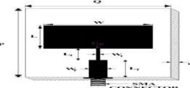
permittivity εr = 4.2. Figure 1 shows the geometry of CRMA designed on a substrate of area P × Q
using the basic equations available in the literature [6]. The Patch element is designed for the resonant frequency of 4 GHz. The CRMA consists of radiating patch of length L and width W. The feed
arrangement consists of quarter wave transformer of length Lt and width Wt which is used for better
impedance matching between the microstripline feed of length Lf , width Wf and center point (Cp)
along the width of the rectangle microstripline patch. At the tip of microstripline feed a 50Ω coaxial SMA connector is used for feeding the microwave power.
Figure 2 shows the geometry of pair of triangular slots and pair of rectangular slots rectangular microstrip antenna (PTSPRSRMA). Here the Two triangular slots and two rectangular slots are placed
along the width of the patch .The dimension of slots are taken in terms of λ0, where λ0 is the free space
wavelengths in cm .
Figure 2 Geometry of PTSPRSRMA
Figure 3 Geometry of PTSPRSПRMA
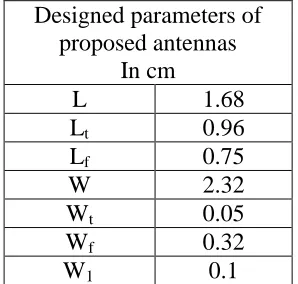
Further, two vertical slots are added along the length of PTSPRSRMA. This antenna is named as pair of triangular slots and pair of rectangular slots П rectangular microstrip antenna (PTSPRS П RMA) which is derived from PTSPRSRMA as shown in Fig.3. The design parameters of CRMA, PTSPRSRMA and PTSPRSПRMA are given in Table 1.
Designed parameters of proposed antennas
In cm
L 1.68
Lt 0.96
Lf 0.75
W 2.32
Wt 0.05
Wf 0.32
III. EXPERIMENTAL DETAILS
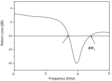
The impedance bandwidth over return loss less than -10dB for the proposed antennas is measured on vector network analyzer. The variation of return loss versus frequency of CRMA is as shown in Fig. 4. It is clear from this figure that, the antenna resonates for the design frequency of 4 GHz. This validates the design concept of CRMA. Further from Fig. 4 it is seen that, the antenna resonates for
single band of frequency BW1. The magnitude of BW1 is found to be 3.50 %. This is calculated using
the equation,
2 1
Impedance bandwidth 100 %
c f f f
where f2 and f1 are the upper and lower cutoff frequencies respectively, when its return loss
reaches -10dB and fc is the center frequency between f1 and f2.
The variation of return loss versus frequency of PTSPRSRMA is as shown in Fig. 5. From this
figure it is seen that, the antenna resonates for quadband of frequencies BW2, BW3, BW4 and BW5, .The
magnitude of each operating band is found to be 4.49 %, 5.75 %, 3.66 % and 7.13% respectively. The
multiband operation is due to the independent resonance of Patch and slots inserted in the conducting
patch of PTSPRSRMA [7]. By the construction of novel geometry of PTSPRSRMA, the antenna starts
resonating higher than the designed frequency of 4 GHz.
Figure 6 shows the variation of return loss verses frequency of PTSPRSПRMA. From this figure
it is seen that, the antenna resonates for quad band of frequencies i.e. for BW6 ,BW7, BW8 and BW9, .
The magnitude of each operating band is found to be 10.32 %, 3.92%, 3.70 % and 6.66% respectively.
It is clear from the figure that the BW6 operating bands is enhanced 2.29 times compare to
PTSPRSRMA
Figure 4. Variation of return loss versus frequency of CRMA
-20 -15 -10 -5 0 Bw5 Bw4 Bw3 18 16 14 12 10 8 6 4 2 Re turn Lo ss (dB) Frequency (GHz) Bw2
The gain of the proposed antennas is measured by absolute gain method [8].The power
transmitted Pt by pyramidal horn antenna power received Pr by antenna under test (AUT) is measured
independently. With the help of these experimental data, the gain (G) in dB of AUT is calculated by using the formula,
dB r
t dB 0dB t
λ P
= 10 log - - 20log
P 4πR
G G
where Gt is the gain of the pyramidal horn antenna and R is the distance between the transmitting
antenna and AUT. Using above equation the peak gain of PTSPRSRMA and PTSPRSПRMA measured in their operating bands is found to be 2.01 and 4.50 dB respectively. Hence by the construction of PTSPRSПRMA enhances the gain by 1.90 times more than the peak gain of PTSPRSRMA.
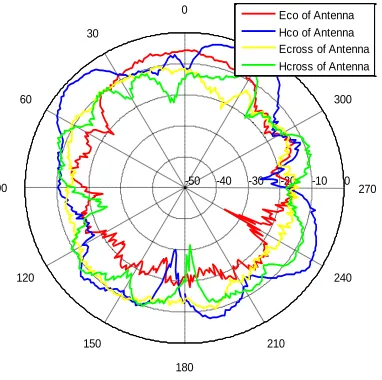
The radiation patterns of antenna are measured in an anechoic chamber. The co and cross-polar patterns in E- plane and H- plane of the antenna are presented in Fig. 7-9. From these figures it is clear that, the E and H plane patterns.
-30 -25 -20 -15 -10 -5 0 Bw6 Bw8 Bw7 18 16 14 12 10 8 6 4 2 R e tu rn L o ss (d B) Frequency (GHz) Bw6
Figure 6. Variation of return loss versus frequency of PTSPRSПRMA
Figure 7. E and H plane radiation patterns of CRMA measured at 3.97 GHz. 0 -10 -20 -30 -40 -50 0 30 60 90 120 150 180 210 240 270 300 330
Figure 8. E and H plane radiation pattern of PTSPRSRMA measured at 10.0 GHz.
Figure 9. E and H plane radiation patterns of PTSPRSПRMA measured at 8.18 GHz.
IV. CONCLUSION
From the detailed experimental study it is concluded that, by using Two rectangle slots and Two triangle slots in CRMA i.e., PTSPRSRMA makes the antenna to resonate for quadband of frequencies and gives a peak gain of 2.01 dB. Further by adding two rectangle slots i.e., PTSPRSПRMA. The antenna resonates for quad bands and gives a maximum impedance bandwidth of 10.32%. This antenna also enhances the gain to 4.50 dB when compared to the gain of PTSPRSRMA without changing much in the radiation characteristics. These antennas may find application SAR and microwave communication systems operating at c to ku bands.
REFERENCES
[1] X.Wang,W.Chin, and Z.Feng, Multiband antenna with parasitic branches for laptop applications .Electron Lett 43(2007),1012-1013.
D.M.Pozar “Microstrip antennas”,IEEE Proc.,Vol.80,pp.79-91,January 1992
0 -10 -20 -30 -40 -50 0 30
60
90
120
150
180
210
240 270 300 330
Eco of Antenna Hco of Antenna Ecross of Antenna Hcross of Antenna
0 -10 -20 -30 -40 -50 0 30
60
90
120
150
180
210 240
270 300 330
[3] H. W. Lai and K. M. Luk, “Wideband stacked patch antenna fed by meandering probe,” Electronics Letters, vol. 41, no. 6,pp. 297–298, 2005
[4] E.chang, S.A.Long, and W.F. Richard, experimental investigation of electrically thick rectangular microstrip antennas,IEEE Trans antenna propagation Ap-34 (1986),767-772
[5] L.Liu and H.-J. Liu, compact triple slotted monopole antenna with asymmetric CPW grounds, Electron Lett 37 (2006),840-842
[6] I. J. Bhal and P. Bharatia, (1981), “Microstrip antennas”. Artech House, New Delhi
[7] Sameena, Konda and Mulgi, “A Novel slot for enhancing the impedance bandwidth and gain of rectangular microstrip antenna”, PIERS C, Vol.11, pp. 11-19, 2009.